Transcription
Scour Considerations withinAASHTO LRFD DesignSpecificationsTechBriefThe Scour Program is anintegrated national effort toaddress or mitigate erosion ofstreambed or bank material dueto flowing water; includingerosion localized around bridgeabutments and piers.The Scour Program alsoaddresses bridges withfoundation elements that are orhave the potential to be unstablefor the observed or evaluatedscour condition.The Federal HighwayAdministration manages theProgram through partnershipswith state highway agencies,industry and academia.The Program’s primary goalsare to improve safety andresilience of the nation’sbridges.Office of Bridges & StructuresFHWA-HIF-19-060Date: 3 March 2021This Technical Brief (TechBrief) provides programmatic and technicalconsiderations for understanding the interaction of limit states andscour depths in foundation design related to provisions of the AmericanAssociation of State Highway and Transportation Officials (AASHTO)Load and Resistance Factor Design (LRFD) Bridge DesignSpecifications.The contents of this document do not have the force and effect of law and arenot meant to bind the public in any way. This document is intended only toprovide clarity to the public regarding existing requirements under the law oragency policies. While this is non-binding guidance, compliance withapplicable statutes or regulations cited in this document is required.1INTRODUCTIONThe American Association of State Highway and TransportationOfficials (AASHTO) “Load and Resistance Factor Design BridgeDesign Specifications” (LRFD) (AASHTO, 2017) is the standard forhighway bridge and structure design, evaluation, and rehabilitationpractice. The standard is incorporated by reference into FederalHighway Administration (FHWA) regulations in the Code of FederalRegulations (CFR), Title 23, Highways (23 CFR 625.4(d)(1)(v)). TheAASHTO LRFD specifications contain chapters, articles andcommentary governing the engineering design of structural (e.g., bridgesuperstructures, decks, etc.), geotechnical (e.g., foundations, piers,abutments, retaining walls, etc.), hydraulic (e.g., hydrology, hydraulics,and scour), and other elements for these types of highwayinfrastructure.The first portion of the TechBrief will describe common terminologyrelated to LRFD and scour and the general application of the AASHTOLRFD specifications to scour design. The TechBrief later providesscenarios to illustrate various design flow conditions and how to applyAASHTO LRFD and scour for each scenario.This TechBrief describes how bridge owners and designers can considerscour-related provisions in AASHTO LRFD when designingfoundations while aligning with compliance requirements of FHWA’sDesign Standards (23 CFR part 625) and National Bridge InspectionStandards (23 CFR part 650, subpart C). This document does notconstitute a standard, specification, or regulation.The AASHTO describes LRFD as taking the “variability in thebehavior of structural elements into account in an explicit manner.LRFD relies on extensive use of statistical methods, but sets forth theresults in a manner readily usable by bridge designers and analysts.”(AASHTO, 2017). Additionally, AASHTO defines the term “Load and
FHWA-HIF-19-060Resistance Factor Design” as “A reliability-based design methodology in which force effectscaused by factored loads are not permitted to exceed the factored resistance of the components.”As the term “LRFD” denotes, quantification and probabilistic considerations related to forces(i.e., loads) and capabilities to withstand those forces (i.e., resistance) inform the application ofthe design specifications.This is accomplished through consideration of limit states or, as defined by AASHTO LRFD, a“condition beyond which the bridge or component ceases to satisfy the provisions for which itwas designed.” In practice, bridge engineers would factor the capacity and demand upon bridgesuperstructures, substructure and foundation elements for evaluation at all applicable limit states.This is not the case for scour design. The FHWA regulations in 23 CFR § 650.305 define scouras “erosion of streambed material due to flowing water; often considered as being localizedaround piers and abutments of bridges.” “Erosion” is the operative word in FHWA’s definition.Similarly, AASHTO LRFD considers scour not as a force, but a change in foundationconditions (i.e., loss of bed material above the scour line). In other words, scour depth is acondition that has resulted from erosive forces and AASHTO LRFD considers this conditionfor applicable limit states. There are currently no statistically-based factors applied to scourdepth or its effect to a foundation.This becomes more problematic as the design of bridge foundations to accommodate scourinvolves close coordination and collaboration of the hydraulics, geotechnical, and structuralengineering disciplines. While each of these disciplines have specifications, guidance, andterminology specific to the topic, these are not necessarily well understood by members of theother two disciplines.Therefore, one of the goals of this TechBrief is to provide some clarification of scour and scourdepths for these various disciplines. The TechBrief describes various AASHTO LRFD andFHWA terms and scenarios to illustrate the various conditions, including limit states. Finally,this document provides clarification on FHWA approaches and recommendations.1.1A NOTE ON NOMENCLATUREAs an overview of scour and relevant provisions in AASHTO LRFD, this TechBrief uses andapplies terms, concepts, and nomenclature not typically used in some areas of the transportationcommunity.To assist the audience, this TechBrief signifies terms defined by FHWA or AASHTO bycombining italics and font color. Examples include limit state or scour or design flood forwaterway opening.Providing these indicators to distinguish the origins of the terms is important to allow theaudience to properly recognize and understand context.This usage includes instances when the term or nomenclature requires a plural (e.g., limit stateinto limit states), or denotes an action or change in tense (e.g., scour into scoured), or othergrammatical usage or constructions.Sometimes, terminology might reflect the combination of several defined terms. For example,“design flood for bridge scour” describes and uses the terms scour and design flood.3 March 2021Page 2 of 17
FHWA-HIF-19-0601.2REGULATORY BASISThis TechBrief will provide State Departments of Transportation (State DOTs) with additionalcontext and information to understand the FHWA’s regulations in 23 CFR. The FHWA requirescompliance with 23 CFR and other regulations for a project to be eligible for Federal-aid or otherFHWA participation or assistance [23 CFR § 630.112(a)].The following FHWA regulations apply to highway projects and actions interacting with andwithin waterways and floodplains (paraphrased for brevity):23 CFR part 625 – Design Standardsa. National Highway System (NHS) projects must follow hydrologic, hydraulic, and scourrelated sections of the AASHTO LRFD Bridge Design Specifications [§ 625.3(a)(1) and§ 625.4(b)(3)].b. Non-NHS projects must follow State DOT drainage and/or bridge standard(s) andspecifications [§ 625.3(a)(2)].23 CFR 650 subpart A – Location and Hydraulic Design of Encroachments on FloodPlainsa. All Federal-aid projects, whether on the NHS or Non-NHS require Hydraulic DesignStandards. Neither State, local, nor AASHTO standards may change or override the§650.115 design standards. The design standards require development of a “DesignStudy” or certain analyses for each action in an encroachment (§ 650.115(a)).b. Content of Design Studies [§ 650.117]. This regulation requires studies to contain thehydrologic and hydraulic data and design computations [§ 650.117(b)]. As bothhydrologic and hydraulic factors and characteristics lead to scour formation, such dataand computations apply to scour as well. Project plans must show the water surfaceelevations of the base flood (i.e., 100-year flood) and overtopping flood [§ 650.117(c)].23 CFR 650 Subpart C – National Bridge Inspection Standardsa. Defines Scour and Scour Critical Bridges [§ 650.305].b. Requires identification of “ bridges that are scour critical” [§650.313(e)].c. For those scour critical bridges, requires preparing “ a plan of action to address critical findings.” [§ 650.313(e)(3)].1.3UPDATED MATERIALSThis TechBrief provides updated and improved information for:1. Hydraulic Engineering Circular (HEC) No. 18, “Evaluating Scour at Bridges,” 5th edition,(HEC-18) (FHWA, 2012). Specifically:a. TechBrief Section 2.4.3 and 2.4.6 are scenarios depicting low tailwater conditions,provides further clarification to include ‘low tailwater controlling conditions’ in theguidance provided in HEC-18, Chapter 2, Section 2.1, Page 2.2, 2nd paragraph andSection 2.5.2, Page 2.16, 3rd paragraph.This TechBrief does not update, change nor supersede any other information in the HEC-18document nor other FHWA materials.3 March 2021Page 3 of 17
FHWA-HIF-19-0601.4GLOSSARYThis TechBrief uses and references the following terms obtained from FHWA regulations andAASHTO LRFD Sections, Articles and Definitions. Only the definitions contained in FHWAregulations or in AASHTO LRFD Sections that are incorporated by reference into thoseregulations are legally binding. The Glossary also includes several TechBrief specific terms toaid in readability and context. Finally, this Glossary provides the relevant citation of each source:23 CFR §650.105 [Definitions]Base Flood – Shall mean the flood or tide having a 1 percent chance of beingexceeded in any given year.Design Flood – Shall mean the peak discharge, volume if appropriate, stage or wavecrest elevation of the flood associated with the probability of exceedance selected forthe design of a highway encroachment. By definition, the highway will not beinundated from the stage of the design flood.Overtopping Flood (QOT) – Shall mean the flood described by the probability ofexceedance and water surface elevation at which flow occurs over the highway, overthe watershed divide, or through structure(s) provided for emergency relief.23 CFR § 650.305 [Definitions]Scour – Erosion of streambed material due to flowing water; often considered asbeing localized around piers and abutments of bridges.Scour Critical – A bridge with a foundation element that has been determined to beunstable for the observed or evaluated scour condition.AASHTO LRFD § 1.2 - DefinitionsDesign Life – Period of time on which the statistical derivation of transient loads isbased: 75 years for these Specifications.Extreme Event Limit States – Limit states relating to events such as earthquakes, iceload, and vehicle and vessel collision, with return periods in excess of the design lifeof the bridge.Factored Load – The nominal loads multiplied by the appropriate load factorsspecified for the load combination under consideration.Factored Resistance – The nominal resistance multiplied by a resistance factor.Limit State – A condition beyond which the bridge or component ceases to satisfy theprovisions for which it was designed.Load and Resistance Factor Design (LRFD) – A reliability-based designmethodology in which force effects caused by factored loads are not permitted toexceed the factored resistance of the components.Load Factor – A statistically-based multiplier applied to force effects accountingprimarily for the variability of loads, the lack of accuracy in analysis, and theprobability of simultaneous occurrence of different loads, but also related to thestatistics of the resistance through the calibration process.Nominal Resistance – Resistance of a component or connection to force effects, as by permissible stresses, deformations, or specified strength of materials.Resistance Factor – A statistically-based multiplier applied to nominal resistanceaccounting primarily for variability of material properties, structural dimensions andworkmanship, and uncertainty in the prediction of resistance, but also related to thestatistics of the loads through the calibration process.3 March 2021Page 4 of 17
FHWA-HIF-19-060AASHTO LRFD § 2.2 – DefinitionsCheck Flood for Bridge Scour – Check flood for scour. The flood resulting fromstorm, storm surge, tide, or some combination thereof having a flow rate in excess ofthe design flood for scour, but in no case a flood with a recurrence interval exceedingthe typically used 500 years.Design Flood for Bridge Scour – The flood flow equal to or less than the 100-yearflood that creates the deepest scour at bridge foundations. The highway or bridge maybe inundated at the stage of the design flood for bridge scour. The worst-case scourcondition may occur for the overtopping flood as a result of the potential for pressureflow.Design Flood for Waterway Opening – The peak discharge, volume, stage, or wavecrest elevation and its associated probability of exceedance that are selected for thedesign of a highway or bridge over a watercourse or floodplain. By definition, thehighway or bridge will not be inundated at the stage of the design flood for thewaterway opening.AASHTO LRFD § 3.2 – DefinitionsLoad – The effect of acceleration, including that due to gravity, imposed deformation,or volumetric change.Nominal Load – An arbitrarily selected design load level.HEC-18 – DefinitionsHydraulic Design Flood – is equivalent to AASHTO LRFD definition of Design Floodfor Waterway OpeningScour Check Flood – is equivalent to AASHTO LRFD definition of Check Flood forBridge ScourScour Design Flood – is equivalent to AASHTO LRFD definition of Design Flood forBridge ScourScour Depth or Depth of Scour – The vertical distance a streambed is lowered byscour below a reference elevation.Total Scour – The sum of long-term degradation, general (contraction) scour andlocal scour.Specific TechBrief Terminology (non-regulatory)Foundation Element – A footing, pile, or other type of foundation associated with abridge (or culvert).Incipient overtopping – The point at which overtopping is beginning to occurLow Tailwater Flow (QLT) – This condition occurs if high flow from a channel entersa low water boundary condition, in relatively close proximity, downstream of astructure.Worst Case Scour Depth – The conditions (e.g., discharge, velocity, depth, tailwater,geometry, orientation, type of foundation, etc.) that would produce the maximumscour depth at a particular foundation element.3 March 2021Page 5 of 17
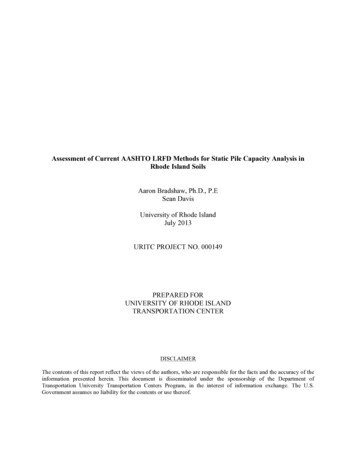
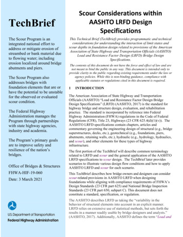
FHWA-HIF-19-0601.5Influencing-Element Examples in Determining Worst Case Scour DepthFigure 1 illustrates the relationship between flood discharge, tailwater and the associated scourdepths. Specifically, Figure 1 depicts the worst-case scour depth; with several alignedillustrations and plots used to convey various elements. Figure 1’s top left plot depicts how scourdepth varies with increasing flow rate at various tailwater levels (TW). This top left plot includesthe critical depth line (yc line ) demonstrating the lower bounds of TW depth.The top right illustration represent a color ramp scale of scour depth; with the deepest blue colorsrepresent the shallowest scour depth and the darkest red the deepest scour depth.The two illustrations on the bottom of Figure 1 depict the scour progression versus discharge atthe yc line . The bottom left plot shows how some specific tailwater level (TWi) generates theworst-case scour depth (yS,max ), which is the deepest scour within the range of considereddischarges and possible tailwater levels. For Figure 1, this worst-case scour depth, yS,max , occursat Qj and TWi.The bottom right illustration depicts a profile view of the waterway, bridge, bridge foundationand scour hole; designating yS,max , Qj and TWi.Figure 1. Worst-case scour depth.This TechBrief will attempt to describe and depict other potential concepts and scenarios withinAASHTO LRFD and FHWA approaches.2FOUNDATIONS & SCOUR WITHIN THE CONTEXT OF AASHTO LRFDThe FHWA regulation 23 CFR § 625.4(b)(3) [Design Standards] requires use of the “AASHTOLRFD Bridge Design Specification” for projects on the National Highway System (NHS).3 March 2021Page 6 of 17
FHWA-HIF-19-060Additionally, under their § 625.3(a)(2) authorities, many State DOTs adopt this document for useon non-NHS projects as well.As a result, this TechBrief focuses on the interaction of foundations and scour within the contextof AASHTO LRFD. In doing so, this section of the TechBrief provides more detailedexplanations of the scour-related AASHTO LRFD articles and their relationship to foundations.Unless specifically cited with a regulation, these TechBrief discussions only represent technicalconsiderations and processes.Note, this Tech Brief does not distinguish how AASHTO LRFD specifications address deepfoundation and shallow foundations. The figures in this TechBrief incorporate deep foundationsfor illustration purposes only.2.1AASHTO LRFD Foundation DesignIn the design of a foundation, AASHTO LRFD requires the consideration of structural andgeotechnical conditions, and the load combinations specified in Service, Strength, and ExtremeEvents limit states.The LRFD design methodology uses load factors to account, primarily, for the variability ofloads, the uncertainties in load evaluation, and the probability distribution for potentialcombinations of different loads, but also related to the statistics of the resistance through thecalibration process. It uses resistance factors to account for, primarily, uncertainties in materialproperties, geometric variation from fabrication process, and capacity analysis, but also related tothe loads through the calibration process.The combination of factored loads (i.e., the sum of products of nominal loads and load factors)cannot exceed the factored resistance (i.e., nominal resistance of the component multiplied by aresistance factor). If it does, the bridge or bridge component no longer satisfies the specific limitstate and therefore, no longer fulfils the target reliability embedded in AASHTO LRFD.2.2LRFD Application to Scour DesignWhile the foundation scenario described above where LRFD applied factored loads and factoredresistance, this is not the case for how LRFD accounts for scour.Essentially, there are several circumstances and reasons why LRFD accounts for scour in adifferent manner than structural and geotechnical approaches: Bridge hydraulic practice essentially looks at two types of design situations (i.e., waterwayopening and scour) and applies two discrete discharges (i.e., design flood for waterwayopening (hydraulic design flood), and design flood for bridge scour (scour design flood)).Distinctions include: The hydraulic design flood focuses on flooding, backwater, and overtopping issueswhile scour design flood focuses on conditions affecting foundation integrity. The concept of a “check event” only applies to the scour design, not the waterwayopening design (i.e., there is no explicit check condition for the waterway opening)Such distinctions may introduce conflicting design constraints (i.e., the design constraintsfor flooding may not be the same for scour). Scour develops as a result of hydrostatic and hydrodynamic forces upon the waterway bedmaterial; eroding that material, and potentially exposing foundation elements.3 March 2021Page 7 of 17
FHWA-HIF-19-060 Current methods for assessing scour depth apply observations or predictive evaluations. For observed scour, current hydraulic methods often are not able to deconstruct the flowconditions that produced the scour depth; thus being unable to capture the associatedexceedance probability. For predictive scour, evaluations may not consider the geotechnical properties of the bedmaterial; instead applying conservative assumptions (i.e., non-cohesive material extendingthroughout the geological strata) and quasi-empirical equations. The current foundation design in AASHTO LRFD does not take into account the combinedeffect of variability of foundation element resistance and variability of scour depth. As aresult, there are no statistically-based factors dedicated to the effects from scour. The FHWA provisions and AASHTO LRFD provisions related to scour use discharge (i.e.,flood or flows) as a (at least) third order surrogate for determining scour depth. For eachwaterway, practice uses the discharge to estimate resultant flow depths and velocity (i.e.,second order surrogates); which in turn estimate scour depth. In other words, specifying adischarge may not capture the different erosion forces and load vectors and componentsacting on the soil at bridge foundations. Scour depth does not necessarily increase with discharge. Therefore, applying a scourcheck flood associated with Q500 that is greater than the scour design flood associated withQ100 may not yield an increased scour depth nor represent the worst case scour. Applying discrete discharges neglects that worst case scour formation may NOT occur atthose discharges. 1 The worse-case scour depth at some bridge foundation element mayoccur at a discharge with an exceedance probability less than the design life or even thehydraulic design flood. Alternatively, worst case scour may occur at flood exceedanceprobabilities larger than such discrete discharges.Since LRFD considers scour not as a force but as a change of foundation condition, i.e. loss ofbed material, the following sections describe how scour is addressed in the LRFD methodology.2.3Scour Design Flood & Scour Check FloodLRFD seeks to provide a buildable, serviceable bridge, capable of safely carrying design loadsfor a specified design life. This translates to satisfying various limits states, of which eachconsists of a unique combination of permanent, transient or extreme loads and/or conditions.Another way to look at this approach is that bridges must satisfy normal operational needs, butalso address situations such as seismic events or vessel collisions. AASHTO LRFDaccomplishes some of these such needs by designing at multiple limit states. For example,Strength III checks for a very high wind speed (design wind) condition, while Strength Vprescribes a moderately high wind speed that allows normal operation.AASHTO LRFD applies this concept to scour design as well. The scour design flood, associatedwith the flood with an 1% annual exceedance probability (i.e., 100-year return period, or, Q100),represents the “normal” scour depth condition. The scour check flood, associated with the 0.2%The 1962 scour induced I-29 Big Sioux River bridge collapse occurred at approximately the waterway openingdesign flood (i.e., 50-year exceedance discharge for an Interstate Highway Bridge) (FHWA, 1963).13 March 2021Page 8 of 17
FHWA-HIF-19-060annual exceedance discharge probability (i.e., 500-year return period or Q500), represents the“check” condition.AASHTO selected these 100-year and 500-year flood discharges based on recommendationsfrom FHWA and in alignment with the National Bridge Inspection Standards (NBIS) regulation(23 CFR § 650 subpart C). Specifically, in the late 1980s, when developing the FHWA ScourProgram, the FHWA recommended use of 100-year and 500-year exceedance discharges as thescour design flood and scour check flood. 22.4Scenarios Depicting Different Situations Covered by LRFD & ScourAASHTO LRFD recognizes that the worst case scour depth may not occur at the highest flowrate that the scour design flood or scour check flood may have (i.e., Q100 and Q500 events). So, thescour design flood might consist of some flood magnitude less than the Q100 that causes greaterscour at the bridge. If so, the specifications require using that discharge as the scour designflood. Similarly, if there is a flood event less than the Q500 that causes the worst case scour depthat the bridge, it should be used as the scour check flood. Another way of stating the above is thatthe scour design flood should be the worst-case scour for all floods up to and including Q100.Likewise, the scour check flood should be the worst-case scour for all floods up to and includingthe Q500.For the bridge design considering scour, AASHTO LRFD Section 2.6.4.4.2 has the followingrequirements:For the design flood for scour, the streambed material in the scour prism above the totalscour line shall be assumed to have been removed for design conditions.The design flood storm surge, tide, or mixed population flood shall be the more severe ofthe 100-yr events or from an overtopping flood of lesser recurrence interval.AASHTO LRFD Section 2.6.4.4.2 also requires:For the check flood for scour, the stability of bridge foundation shall be investigated forscour conditions resulting from a designated flood storm surge, tide, or mixed populationflood not to exceed the 500-yr event or from an overtopping flood of lesser recurrenceinterval. Excess reserve beyond that required for stability under this condition is notnecessary. The extreme event limit state shall apply.To illustrate some (but not all) of the different situations covered by AASHTO LRFD and scour,this TechBrief will cover several different scenarios.For the sake of clarity, the TechBrief places each scenario on a separate page.AASHTO incorporated these into pre-LRFD bridge standards and specifications. When developing the LRFD,AASHTO essentially kept these prior approaches.23 March 2021Page 9 of 17
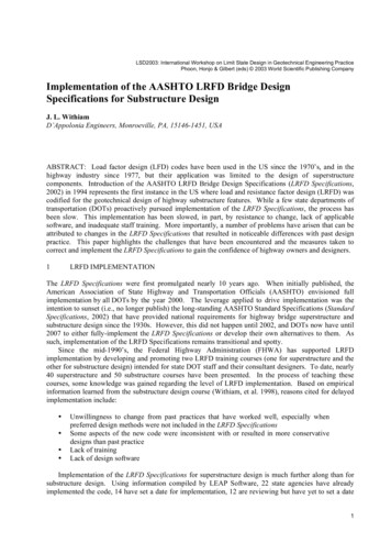
FHWA-HIF-19-0602.4.1 Scenario 1: Scour design flood equals the Q100 floodFigure 2 illustrates the scour progression versus discharge that generates the worst-case scourdepth, relative to the bridge foundation. The maximum scour depth is on the upstream side of thebridge structure.In this scenario, the worst-case scour depth (yS,Q100 ) as depicted in the left-side plot and profileillustrations, occurs at Q100 and serves as the scour design flood.Figure 2. Worst-case scour depth for Q100 used for scour design flood.3 March 2021Page 10 of 17
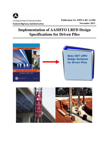
FHWA-HIF-19-0602.4.2 Scenario 2: Scour design flood equals the QOT floodFigure 3 depicts an alternate scenario where incipient overtopping flood at the roadwayapproaches occurs, and the worst-case scour depth does not occur at Q100, but rather at theincipient overtopping flood, labeled as QOT.In this scenario, there is hydraulic relief provided at QOT, so that Q100 causes a shallower scourdepth, as reflected in the plots on the left.The left plot and profile illustrations depict the worst-case scour depth (yS,QOT ) for this scenario.The flood discharge in this scenario shows the water level is higher relative to the bridgestructure. For this case, the scour design flood uses the QOT condition.Figure 3. Incipient overtopping flood generates the worst-case scour depth for the scour designflood.3 March 2021Page 11 of 17
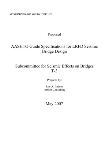
FHWA-HIF-19-0602.4.3 Scenario 3: Scour design flood equals the QLT floodFigure 4 depicts a low tailwater flow condition case.In this scenario, a low flow generates higher velocities at the bridge structure for low TWconditions, while higher flows reduce velocities at bridge structure due to increasing TW.For example, a bridge structure is located at a tributary stream close to a river confluence. Duringa storm event, flow from the tributary goes through critical depth (yc-line) before entering thereceiving stream with low tailwater (low flow depth) generating high velocities at the bridgestructure. As the storm progresses, the depth in the receiving stream increases, creating highertailwater conditions for the tributary and reducing velocities at the bridge structure.In this case, the worst-case scour depth occurs at a low tailwater flow condition (QLT) and TWi,which occurs for flows lower than the Q100. Figure 4 designates this worst-case scour depth asyS,QLT (as depicted in the bottom plot and profile illustrations). QLT is used as the scour designflood.Conditions in this scenario are similar to those that occurred in the April 1962 flood events thatled to the I-29 Big Sioux River bridge collapse.Figure 4. Low tailwater flow generates the worst-case scour depth for the scour design flood.3 March 2021Page 12 of 17
FHWA-HIF-19-0602.4.4 Scenario 4: Scour check flood equals the Q500 floodWhile Figures 2 thru 4 showed the worst-case scour depths related to Q100, the following threefigures depict similar scenarios, but for Q500.Figure 5 illustrates the relationship between flood discharge and the associated scour depth up toQ500.The illustrations below show the scour progression versus discharge that generates the worst-casescour depth relative to the bridge foundation.In this scenario, the worst-case scour depth occurs at the upstream side of the bridge structure atthe Q500; designated as yS,Q500 (as depicted in the plot and profile illustrations).These conditions would constitute the scour check flood.Figure 5. Q500 generates the worst-case scour depth for the scour check flood.3 March 2021Page 13 of 17
FHWA-HIF-19-0602.4.5 Scenario 5: Scour check flood equals the QOT floodFigure 6 shows the alternate scenario where incipient overtopping flood occurs.The worst-case scour depth does not occur at Q500, but rather at a lesser incipient overtopping flood(greater than Q100). Figure 6 labels this flood as QOT.Figure 6 designates this worst-case scour depth as yS,QOT (as depicted in the plot and profileillustration).For this case, the QOT is used as the scour check flood.Figure 6. Incipient overtopping flood generates the worst-case scour depth for the scour checkflood.3 March 2021Page 14 of 17
FHWA-HIF-19-0602.4.6 Scenario 6: Scour check flood equals the QLT floodFigure 7 once again depicts the special case (see scenario 3), a low tailwater flow condition. Inthis scenario, the worst-case scour depth is at the QLT and TWi, which occurs for flows greaterthan Q100 and lower than the Q500, should be used as the scour check flood.Figure 7. Low tailwater flow generates the worst-case scour depth for the scour check flood.2.4.7 Other ScenariosAn impor
related sections of the AASHTO LRFD Bridge Design Specifications [§ 625.3(a)(1) and § 625.4(b)(3)]. b. Non-NHS projects must follow State DOT drainage and/or bridge standard(s) and specifications [§ 625.3(a)(2)]. 23 CFR 650 subpart A - Location and Hydraulic Design of Encroachments on Flood Plains