Transcription
Advances in Engineering Research, volume 196International Joint Conference on Science and Engineering (IJCSE 2020)Weather Monitoring Telemetry System Based onArduino Pro Mini With Antenna Tracker UsingTransceiver Module SV651 and SV611Rifqi Firmansyah1,* Muhammad Badruddin A. Mustofa1, Muhammad Eko Prasetya1,Pressa P. Surya Saputra21Department of Electrical Engineering, Universitas Negeri Surabaya, Surabaya 60213, IndonesiaDepartment of Electrical Engineering, Universitas Muhammadiyah Gresik, Gresik, Indonesia*Corresponding author. Email: rifqifirmansyah@unesa.ac.id2ABSTRACTThe progress of space technology in various countries is increasing rapidly. In Indonesia, there is a Non-GovernmentOrganization Ministry of Indonesia who carries out government duties in the field of aerospace research, developmentand utilization. The institute is known as LAPAN (National Institute of Aeronautics and Space), which has four mainfields namely remote sensing, aerospace technology, space science and aerospace policy. One of the main areas thatare important and needed by society is weather monitoring. The weather is always changing in a short time and makeit difficult to predict using human senses. Weather monitoring can be performed by considering the parameters of theatmosphere. However, LAPAN still uses weather monitoring tools purchased from Japan to read those parameters.The main objective of this study is to develop a weather monitoring system related to parameters in the atmosphereand that system can transmit data over long distances in real-time using 433 MHz radio frequency and it is equippedwith an antenna tracker. In this study, data have been sent using the SV611 module and received by the SV651module. We have used Arduino pro mini as the main control system that transmits atmospheric data from the sensorsuch as temperature, humidity, air pressure, wind direction, wind speed, latitude, longitude, and altitude. Data receivedsubsequently have been recorded and displayed using a graphical user interface on a personal computer. Theexperimental results show that the system can monitor and transmit atmospheric data using radiofrequency with amaximum transmission range of 12.17 km above sea level. The tracker antenna can move horizontally by 0-360 andvertically by 0-90 following load transfer when it is flown. The GUI can display and save data on a PersonalComputer (PC) in real-time.Keywords: Weather, Atmosphere, SV611, SV651, Antenna tracker, Arduino pro mini, Graphical userinterface1. INTRODUCTIONIn the modern era, many people use and applyadvance technology in many areas such as aeronauticaland astronautical technology. Indonesia known as theisland nation and as a maritime country should be ableto meet the needs of technology in the field of aviationand aerospace. Technology that should be developed inIndonesia right now is the technology in the field ofballoon payloads. The technology focuses on collectingdata in the atmosphere in the form of parameters such asair pressure, temperature and humidity. In other words,the balloon payloads technology is an importantinstrument used in observing weather and climateconditions [1].The utilization of this technology requires a balloonflown and a device to detect the movement of theballoon called tracker antenna. When the balloon releaseto the atmosphere, there is a load comprised of atemperature sensor, humidity sensor, air pressure sensor,and also a GPS used to read and transmit parameter datain the atmosphere and detect the location as well as thealtitude (altitude) so that the tracker antenna canCopyright 2020 The Authors. Published by Atlantis Press B.V.This is an open access article distributed under the CC BY-NC 4.0 license 2
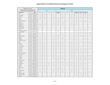
Advances in Engineering Research, volume 196perform tracking automatically [1]. This automatictracking ability influences the control of objects whenmoving and can monitor balloon loads by telemetry byknowing their exact and accurate position. However, inIndonesia to launch or release the balloon payload hasused ground station antenna system, where the control ismanually performed or conventional. This method cancause data received by the antenna inaccurate because itrelies on the operator in positioning and direction ofmovement of the object. Estimates search will become aweaker position when the object is at a long distanceand high speed. Moreover, the system uses payloadspurchased from Japan so that when they conductatmospheric monitoring, they must buy the expensivepayloads.In this paper, we create and develop a monitoringsystem of atmospheric parameters wirelessly usingmodule SV611 and SV651 with a frequency of 433Mhz. We also use Arduino Pro Mini as the maincontroller sending data from some sensors such astemperature and humidity sensors, pressure sensors, andGPS sensors. The system equipped with an antennaautomatic tracking system is then stored and displayedusing the Graphical User Interface on the computer.The remainder of this paper is structured as follows.The components comprising the system are explained insection II. Section III offers system design. Result andDiscussion are presented in section IV. The last sectionis the conclusion.2. METHOD2.1. Components of the SystemThe components comprising the system will beflown to the atmosphere at an altitude of 0 km to 560km above the surface of the Earth. The atmosphere iscomposed of several layers distinguished by somecharacteristics such as gas composition, temperature,and pressure. The transition between layers is gradual[2].The atmospheric layer consists of 5 layers namelythe Troposphere (altitude 6-10 km), Stratosphere(altitude 20-50 km), Mesosphere (altitude 50-85 km),Thermosphere (altitude 85-690 km), and Exosphere(altitude more than 690 km). The atmospheric layer thatmost influences weather conditions on the surface of theearth are the Troposphere to Tropopause [3].Tropopause (10-20 km altitude) is the boundarylayer between the troposphere and the stratosphere.Tropopause layer is marked by temperature inversionconditions along with rising altitude. The uniqueness ofthe Tropopause layer can be observed usingRawinsonda Technology [3].Figure 1 Arduino Pro Mini2.1.1. AntennaThe antenna is a device capable of transmitting andreceiving electromagnetic waves in the air through radiotelemetry. Transmitting an electromagnetic wavedisplacement flow through the transmitter antenna. Thereception is the process of receiving electromagneticwaves flown through the receiver antenna [4].A directional antenna is a type of antenna radiatingand receiving electromagnetic wave signals from one ortwo directions. While the omnidirectional antenna is atype of antenna that can radiate and receiveelectromagnetic wave signals from any direction [5].Antenna implements a wireless communication systemknown as wireless where the cast has a great distancewith good quality [6].2.1.2. Antenna trackerAntenna tracker is a tool that is useful as a tracermovement following the signal source. The device canfollow the direction of the signal moves through thesource of the tracked signal [7]. This tracker can movein two ways namely based on point coordinates of theglobal positioning system (GPS) and the strength of thereceived signal power [8].In principle, the tracker antenna can move based onthe horizontal angle (azimuth) and vertical angle(elevation) [9]. using GPS, antenna tracker candetermine the data in the form of longitude (distance)from the horizontal or azimuth angle and show the datain the form of latitude from the vertical angle ofelevation.2.1.3. Arduino Pro MiniArduino Pro Mini is intended for semi-permanentinstallations on objects. This allows the use of varioustypes of connectors or direct solder cables [10]. ArduinoPro Mini is designed so that the user can use a reset withsoftware running on a computer connected by Arduino.One six-pin pin header is connected to the reset line ofthe ATmega328 through a 100 nF capacitor. This pin isconnected to a hardwire control line of the converter ofUSB-to-serial connected to the header.There are two versions of the Arduino Pro Mini.First, Arduino Pro Mini runs at voltage levels of 3.3Vand 8 MHz, secondly, runs at voltage levels at 5V and16 MHz. Arduino pro-mini-physical form can bepresented in Fig. 1.323
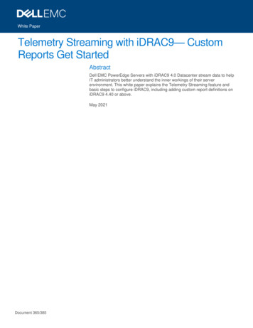
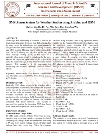
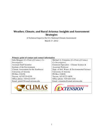
Advances in Engineering Research, volume 196Figure 2 SHT 31 SensorFigure 4 GPS SensorFigure 3 BMP180 Sensor2.1.4. SHT 31The relative humidity is the ratio of the partialpressure of water vapour into water vapour pressure inequilibrium at a certain temperature. It requires lesssteam to achieve high relative humidity at lowtemperatures and low moisture. The relative humiditysensor used is SHT-31D [11].The SHT-31D sensor as shown in Fig. 2 is apremium grade digital humidity and temperature sensorfrom the Sensirion vendor. This is the original versionof the DHTx temperature and humidity sensor. SHT31D has been equipped with I2C communication thatdoes not require a lot of wires and can use many sensorsin the microcontroller or readers. These sensors canwork at a voltage of 2.4V to 5.5V, which means verygood for Arduino, NodeMCU, to the Raspberry Pi.2.1.5. BMP 180The atmospheric pressure sensor is a transducer tomeasure the pressure exerted by the weight of air inEarth's atmosphere. In almost all circumstancesestimated at close to atmospheric pressure hydrostaticpressure is caused by the weight of air above themeasurement point. The sensor used to measure airpressure is the BMP180 module from Adafruit whichcan take measurements from 300 hPa to 1100 hPa oraltitudes of 9000m to -500m from sea level withresolutions up to 0.003 hPa / 0.25m. This sensor is alsocapable of measuring temperatures from -40 C to 85 C [12]. The physical form of the BMP180 sensor ispresented in Fig. 3.2.1.6. Modul GPS Ublox NEO-6MGlobal Positioning System (GPS) is a satellitenavigation system developed and introduced by USDOD (United States Department of Defense). GPSallows the user to locate the geographic positionourselves in terms of latitude, longitude, and altitudeabove sea level. So wherever we are on this earth, wecan know our exact position [13].Figure 5 SV611 TransmitterFigure 6 SV651 ReceiverGPS sensors used for this research are Ublox NEO6M module with a horizontal accuracy of 1 m,accuracy of measurement speeds up to 0.1m / s, andcourse measurement accuracy up to 0.5 degrees. Speedand course measurement data are used as theatmospheric parameters wind speed and wind direction.The physical form of the GPS Module can be seen inFig. 4.2.1.7. Modul SV611 dan SV651SV611 as shown in Fig. 5 is an application ofhighly-integrated RF transceiver device that adopts thehigh-performance Si4432. SV611 provides goodsensitivity, 100mW output power to achieve long RFrange and reliability of RF communication. To keepaway disturbance, SV611 has 40 frequency channelsand configurable Net ID. SV611 is flexible but easy touse, it comes with many parameters, such as frequency,data rate, output power, Net ID, Node ID. Users canconfigure the parameters through a PC or customer’sdevice [14].SV651 presented in Fig. 6 is an Industrial class &highly-integrated RF transceiver module that adopts thehigh-performance Si4432. TTL / 232 /485 can bechosen corresponding to SV651-TTL / SV651-232 /SV651-485. SV651 provides good sensitivity, 500mWoutput power to achieve long RF range and reliable RFcommunication. To reject the disturbance, SV651 has40 frequency channels and configurable Net ID. SV651is flexible but easy to use, it comes with manyparameters, such as frequency, data rate, output power,Net ID, Node ID [15].324
Advances in Engineering Research, volume 196Figure 7 Stepper MotorFigure 9 Arduino Mega 2560Figure 8 DC MotorFigure 10 Rotary Encoder2.1.8. Stepper MotorStepper motor is a motor driven by pulses so that ithas electromagnetic properties, which can convertelectrical pulses into mechanical motion energy. In thestepper motor, there is a coil on the stator while therotor is a permanent magnet. The movement of a steppermotor moves by step or angle so that it can more easilyadjust the position. Stepper motor is divided into 3 typesnamely variable reluctance (VR), permanent magnet(PM), and hybrid [16].The movement has a 45 degree or 90-degree steprotation. Whereas the hybrid type of stepper motor has acombination of VR and PM type stepper, which in itsmovement can have a step of 360 degrees / 200 or equalto 1.8 degrees to be able to reach 3.6 - 0.9 degrees[16][17]. The physical form of the stepper motor ispresented in Fig. 7.2.1.9. Motor DCDC motor as shown in Fig. 8 is a type of electricmotor that converts electrical energy into mechanicalenergy which can turn electricity into motion influencedby rotating rotors. The working principle of this motoris given a current when the electric field will exert aforce, which is exactly what style will provide rotarypower to the coil [18].This type of dc motor was chosen because itfunctions as a horizontal drive, shaped from the azimuthangle of the tracker antenna which has a load ofreflector antennas.2.1.10. Arduino MegaArduino Mega 2560 presented in Fig. 9 is amicrocontroller that uses ATmega2560 microcontrolleric. Arduino Mega 2560 has 54 digital I / O pins with 16analog inputs. This type of Arduino has more spaceusing a 32bit RAM system [19].2.1.11. Rotary EncoderRotary Encoder is an electronic component thatfunctions as monitoring the movement and position of arotating motor shaft. In general, rotary encoders useoptical sensors to generate serial pulses, where pulsesare interpreted as movement, position and direction. Sothat the rotation angle position on the shaft can read andwill be processed into digital data by the rotary encoderin the form of the pulse width. Initial data obtained inthe form of the angular position will be processed by thecontroller and will get new data in the form of speed,direction and position of the shaft rotation [20].The rotary encoder is used in robot control thatrequires high accuracy in positioning such as RobotMechanism, Omni Robot and Robot Tank. In additionto the robot, the rotary encoder can also be used indetermining the direction and speed of the motor drive.The physical form of the Rotary Encoder is shown inFigure 10.2.2. System design2.2.1. Weather Monitoring System DesignIn this weather monitoring systems can be groupedinto three parts, the payload or payload, antenna tracker,and GUI as shown in Figure 11. When flown, the loadreads atmospheric parameters namely temperature,relative humidity, air pressure, wind direction, windspeed, and altitude above sea level. Then the data thathas been obtained by the charge is transmitted and thenreceived by the antenna. The data is sent to a computerusing a USB cable and displayed on the GUI. Becausethe data received by the ground station is still the raw325
Advances in Engineering Research, volume 196Figure 13 Ground Plane GapFigure 11 Weather Monitoring System DesignFigure 14 Reflector Double Biquad Antennareceiver that receives the antenna to get a strong signalreception value [24].Figure 12 Double Biquad Antennadata before it is displayed first computer dataprocessing.By using the data received by the computercalculates the azimuth and elevation angles to be usedfor the antenna to the charge. Calculation results in theform of angular data are then sent to the trackingantenna system (control unit) using a different serialconnection automatically.2.2.2. Antenna DesignIn designing the antenna design, researchers useddirectional antennas. The directional antenna waschosen because the antenna can focus more on receivingdata received by the antenna. Then the type of antennaused is a double biquad antenna, where the antenna ismade of a closed-loop dipole wire with a square-shapeddouble show in Figure 12. Double biquad antenna is amodification or applying the basic design of a biquadantenna that only uses two quad (square) antennas [21][22].The biquad antenna has a ground plane gap which islocated not too far from the dipole circuit to reduceradiation from the back. this also affects the gain andbandwidth values as shown in Figure 13. the smaller theground plane gap, the gain value will be greater but thebandwidth value decreases. and also to reverse if thegreater the value gap ground plane, the gain will besmaller and will widen the bandwidth values [22] [23].The double biquad antenna also has a square reflector asshown in Figure 14. This reflector functions as a signalAnother purpose in making this double biquadantenna lies in the reflector used. Because as a signalamplifier the wider the reflector used, the more powerwill be received. The length and width used in makingreflectors are 152.2 cm and 76.1 cm. Materials used inthe manufacture of reflector antennas are wire netting(ram-ram) which has a value equal signal strength nicecatch by using aluminium [24]. Another considerationfor using this wire is to have a lightweight so that it doesnot overload the antenna and tracker antenna whenmoving.2.2.3. Buffer DesignTo generate maximum signal shot takes a suitabledistance between the antenna and ground. this is neededso as not to cause signal loss when receiving data fromthe transmitter or transmitter.Design buffer used is two buffer for the antenna andsupport for the body or feet from the antenna tracker.Buffer antenna serves as the support to stand. Antennasupports are also used as a container for the mechanicalmotor to move the antenna to the elevation angle. Thewidth of the buffer that is used is 75 cm and the heightbetween the legs or the supporting body is 70 cm.Design of antenna buffer can be seen in Figure 15.The second buffer design that is used as a foot orbody buffer used as the support of the entire antennatracker to remain sturdy and will not be overturnedwhen there is excessive shock, as well as the containercross-section of a motor mechanic and electrical circuitof the antenna tracker. This buffer is designed to usefour legs with a square cross-sectional shape of thecontainer. the height of the supporting leg is 160cm inlength with 30 cm and 60 cm in cross-sectionsrespectively. The body buffer can be seen in Figure 16.326
Advances in Engineering Research, volume 196Figure 17 Transmitter System CircuitFigure 15 Antenna BufferFigure 18 Receiver System2.2.5. Receiver SystemFigure 16 The Body Buffer of Antenna2.2.4. Transmission SystemTransmitter system is a system contained in the load.Which consists of Arduino Pro Mini as the maincontroller. There are three sensors used in the system isthe sensor SHT31 as a reader of relative humidity andtemperature parameters, sensor BMP180 as readers ofair pressure parameters, GPS sensor reader Ublox Neo6as the height and location of the cargo. The powersource uses an 800mAh Li-Po 3 Cell battery. Beforegetting into Arduino Pro Mini there is a voltageregulator module UBEC which will change the voltageof the battery becomes 5volt making it safe for ArduinoPro Mini has a voltage input specification of 5volt. Thedata that has been obtained is then processed byArduino Pro Mini and put together in one package in theform of a data string. Then the data is transmitted to theground station using a module SV611 with 433Mhzradiofrequency. Design of the transmitter system circuitcan be seen in Figure 17.Data transmitted by the payload will be received bythe Ground Station is connected to the antenna moduleSV651 with the same operating frequency is 433Mhzwith SV611 module contained in the charge. SV651modules that are connected in series with the computerwill automatically send data to a computer that will beprocessed and displayed and stored by the GUI. Designof the receiver system can be seen in Figure 18.2.2.6. Tracking SystemA tracking system is a system that can move theantenna automatically follow wherever payload willmove. The system uses an Arduino Mega 2560 as themain controller of the system. Arduino Mega 2560 willreceive data in the form of Azimuth and Elevationangles sent by the GUI. The data that has been receivedis then processed by Arduino Mega 2560 and split intotwo, the azimuth angle to drive the dc motor so that theantenna can track horizontally and the elevation angle tomove the stepper motor so that the antenna can trackvertically. Design of a tracking system circuit can beseen in Figure 19.327
Advances in Engineering Research, volume 196Figure 21 Graph DisplayFigure 19 Tracking System CircuitFigure 22 Location DisplayFigure 20 Parameters Display2.2.7. Graphical User InterfaceData that has been received by the computer will bedisplayed and stored on a computer by the GUI(Graphical User Interface). Before the data is displayed,the GUI perform data processing that is solving thepreviously received data in the form of a data packageof six data atmospheric parameters. After solving it, theGUI will display the data on a computer / laptop screenso that others can easily find atmospheric parameters inreal time. Display of atmospheric parameters can beseen in Figure 20.Atmospheric parameter data is also displayed in theform of two-dimensional graphs so that data from oneanother can be compared directly. The graph shows datasuch as height values comparison with temperature,altitude with relative humidity, altitude by air pressure,the height of the wind direction, and altitude winds.Graph display can be seen in Figure 21.In addition, to display a parameter data and graphsin real-time, the GUI can display the location of thecharge using a two-dimensional map so that loads canbe monitored the moving wherever cargo is located.Location display can be seen in Figure 22.Figure 23 Temperature ChartGUI can also store data on computer parameters sothat any weather monitoring atmospheric parameters arerecorded data in real-time that is saved automatically.Data is stored in .csv format that can be opened usingMicrosoft Excel.3. RESULT AND DISCUSSIONData were collected at the Air Force BasePameungpeuk Garut in West Java by flying a cargousing a hot air balloon. After being flown the cargosuccessfully sends data and is received by the groundstation. The system can send and receive data in realtime from cargo starting to be flown to a maximumheight of 12170.1m above sea level. Also, the GUImanaged to display atmospheric parameters in real-timeand managed to store atmospheric data on personalcomputers.328
Advances in Engineering Research, volume 196Figure 24 Humidity ChartFigure 26 Course ChartFigure 25 Pressure ChartFigure 27 Speed ChartAs shown in Fig. 23 when the payload starts flyingat an altitude of 23.8m, the temperature value is 33.69 C. The temperature decreases with increasing altitude.The last temperature obtained with an altitude of12170.1m is -10.27 C.From the results obtained during tests and experimentsconducted, it can be concluded: 1) The system is able tosend and receive data in real time at an initial height of23.8m to a maximum height of 12170.1m. 2) Thesystem succeeded in getting atmospheric parameter dataneeded for weather observations in the Troposphere (610 Km) to Tropopause (10-20 Km) because thisatmospheric layer is the most influential on weatherconditions on the earth's surface [3]. 3) Antenna trackercan move to the position of the charge wherever theload is located by knowing the azimuth and elevationangle to an altitude of 12170.1m above sea level. 4)GUI is able to display atmospheric parameter data inreal time and store it on a personal computer.In Figure 24 it can be seen that the average humidityalso decreases with increasing altitude. Obtained thevalue of humidity when the payload starts being flownby 53.47% with a height of 23.8m. The last humidityobtained was 1.08% with a height of 12170.1m.Likewise, the air pressure shown in Figure 25, thehigher the payload, the smaller the air pressure in theatmosphere. When the load is starting to be flown, theair pressure value is 1012.85mBar with a height of23.8m. Obtained a final moisture value of 96.55mBarwith a height of 12170.1m.Figure 26 shows that the direction of the windchanges rapidly. When the charge is flown in thedirection of the wind by 182 with a height of 23.8m.When the height of 12170.1m wind direction is 310 .Likewise, also with changes in wind speed that changesrapidly during the load is flown. When the initial chargeis flown, the wind speed of 0.09 m/s with a height of23.8m is obtained and obtained a speed of 6.99 m/s withan altitude of 12170.1m.4. CONCLUSIONThe main objective of this research is to develop andimplement a weather monitoring system with a trackerantenna using SV611 and SV651 modules at afrequency of 433Mhz.REFERENCES[1] Sunandar, Sandi and Agus Mulyana, Design ofOBDH(On-BoardDataHandling)forMeasurement of Atmospheric Parameters and AirImaging. Unikom Repository, 2016.[2] Iswantari, Gita et al., Utilization of theAtmospheric Spectrograph Telescope to Know theEffect of Seasonal Change on the Water Vapor(H2o) Content in the Atmospheric Layer inWatukosek LAPAN Period February 2013-March2014, UM Online Journal, Vol.2, No.1 2014.[3] LAPAN, Guide to theAtmospheric Balloons, 2018.Competitionfor[4] Rois, Muhamad, Design and Build AntennaTracker for Komurindo (Hardware) Contest,Electrical Journal of the University ofMuhammadiyah Malang, 2018.329
Advances in Engineering Research, volume 196[5] Carr, Joseph J., Practical Antenna Handbook 4thEdition, The United State of America, TheMcgraw-Hill Companies, Inc., 2001.[6] Syahrial et al., Simulation Design and Analysis ofCircular Patch Microstrip Antennas at 2.4GHzFrequency for WLAN Applications, NationalSeminar and Electrical Engineering Expo, 2015.[7] Sidqi, Rafi, Bagus Rio Rynaldo, Satya HadiSuroso, and Rifqi Firmansyah, Arduino BasedWeather Monitoring Telemetry System UsingNRF24L01 , In IOP Conference Series: MaterialsScience and Engineering, vol. 336, p. 12024. 2018.[8] Banna, Muhammad Hanif Al., Development ofAntenna Tracker Based on Global PositioningSystem (GPS) for Communication without Crew,Thesis, Surabaya, Sepuluh November Institute ofTechnology, 2018.[9] Adil, Omar, Combining PID & Fuzzy Controllersfor Antenna Azimuth Position Control, Journal ofCihan University College of Engineering. Vol 21(1): pp. 97-108, 2018.[10] Firmansyah, R., A. Widodo, A. D. Romadhon, M.S. Hudha, P. P. S. Saputra, and N. A. Lestari. Theprototype of infant incubator monitoring systembased on the internet of things using NodeMCUESP8266, In Journal of Physics: ConferenceSeries, vol. 1171, no. 1, p. 012015. IOP Publishing,2019.[11] Kusuma, Aditya Tri. et al., Detection of SoilAltitude, Air Pressure and Temperature Systemsfor Monitoring the Health of Sports Activities inthe Arduino-Based Uno R3 Mountains, NationalSeminar on Information and MultimediaTechnology, Yogyakarta Amikom University,February 10, 2018.[12] Gusmanto et al., Design of Early Warning andTracking Systems on Motorcycle Vehicles UsingArduino Nano Microcontrollers, Department ofElectrical Engineering, Faculty of Engineering,Tanjungpura University, Vol 2, No. 1, 2016.[16] Herawan A, Chusnul Tri J, Optimizing theAccuracy of Low-Orbit Satellite Antenna TrackingUsing a 2-Phase Stepper Hybrid Motor(Optimization of Low-Earth Orbit TrackingAntenna Using a 2-Phase Hybrid Stepper Motor).Journal of Aerospace Technology Vol. 11 No. 1,2013: pp. 1-12.[17] Sensirion, Datasheet Sht3x-Dis, August 2016.[18] Prakasa, Thunder Nanda, Door Lock PrototypeUsing Arduino Mega 2560 Based Stepper MotorWith Voice Commands on Android, The thesis ofthe Department of Electrical Engineering,University of Lampung, 2017.[19] Bernando, Victor, Development of VehicleTracking Systems Using GSM and GPS ModulesBased on the Atmega328 Microcontroller, Journalof Information Systems and Technology (Justin),2016.[20] Omron, Datasheet Rotary Encoder E6b2-C, OmronCorporation Industrial Automation Company,2017.[21] Dzulfikar, Dafi et al., Design and Simulation ofBiquad Double Microstrip Antennas at 2.4GHzFrequency. Proceedings of the National PhysicsSeminar (E-Journal) SNF 2016.[22] Kurnianto, Irfan, The Application of DoubleBiquad Antennas for Data Monitoring of WaterLevel Monitoring at 2.4Ghz Frequency". JemberUniversity Digital Repository, 2018.[23] Issac Kuma, Torkodzor Mosses, Fabrication AndOptimization Of Biquad Antennas For WirelessLocal Area Networks, Researchgate, July 2014.[24] Pratomo, Ghali Endar et al., The Effect of Materialin Designing Bolic Antenna Reflector to IncreaseWifi Receipt. Journal of Electrical Engineering atTanjungpura University ". Vol 1, No. 1, 2017.[13] Wijaksono, Nurhadi., Learning Media Wiper andWasher Electrical System in Negeri 1 SedayuJunior High School, Final Project of the Faculty ofEngineering, Yogyakarta State University, 2016[14] Nicerf, Sv611-100mw Industrial Anti-InterferenceWireless Data Transceiver Module, NicerfWireless Technology Co., Ltd. 2018.[15] Nicerf, Sv651-500mw Industrial Anti-InterferenceWireless Data Transceiver Module, NicerfWireless Technology Co., Ltd. 2018.330
atmospheric monitoring, they must buy the expensive payloads. In this paper, we create and develop a monitoring system of atmospheric parameters wirelessly using module SV611 and SV651 with a frequency of 433 Mhz. We also use Arduino Pro Mini as the main controller sending data from some sensors such as temperature and humidity sensors, pressure sensors, and GPS sensors. The system equipped .