Transcription
Autodesk Revit Structure2014 Fundamentals SDCP U B L I C AT I O N S Better Textbooks. Lower Prices.www.SDCpublications.com
Visit the following websites to learn more about this book:Powered by TCPDF (www.tcpdf.org)
Chapter 7Adding Foundations and Structural SlabsIn this chapter you learn how to create wall footings (bearing and retaining),modify step footings, add piers, pilasters, isolated footings, create slabfoundations, and create structural floors.This chapter contains the following topics: Creating Wall Footings Isolated Footings Piers and Pilasters Creating Structural Slabs7–1
7–2
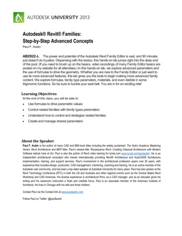
Adding Foundations and Structural Slabs7.1 Creating Wall FootingsLearning ObjectivesCreate bearing or wall footings hosted by walls.Create new foundation wall types.Wall footings for bearing and retaining are placed under wallsand in Autodesk Revit Structure software are actually hostedby the walls. Once a footing is in place, you can change the sizeof the section and add reinforcement, as shown in Figure 7–1, tomake it a foundation bearing system. With the advantages ofhaving a true foundation in place, you can accurately tag andschedule the footings. When a footing size or footing typechanges, the software reads and updates the information whereever it is needed.Figure 7–1 You can apply two types of continuous footing systems, asshown in Figure 7–2; Bearing footings with an equal distanceon either side of the bearing wall and Retaining footings withone side offset to accommodate additional lateral loads andreinforcement.Bearing FootingRetaining FootingFigure 7–2 2013, ASCENT - Center for Technical Knowledge 7–3
Autodesk Revit Structure 2014 FundamentalsHow to:Wall foundations canalso be placed in 3D,section, and elevationviews.Place a Bearing or Retaining Footing1. Create walls or use existing ones. A wall must be in place forthis command to work.2. Open a foundation plan and set it up so that the walls aredisplayed and you can select them.3. In the Structure tab Foundation panel, click(Wall) tostart the Structural Foundations: Wall command, or typeFT.4. In the Type Selector, select a type as shown in Figure 7–3.Figure 7–35. Select a wall, the footing is placed beneath the wall as shownin Figure 7–4.Figure 7–4 To select multiple walls, in the Modify Place WallFoundation tab Multiple panel, click(SelectMultiple). Select the walls using any selection method andclick(Finish) to place the footings. You can flip retaining footings as shown in Figure 7–5Figure 7–57–4 2013, ASCENT - Center for Technical Knowledge
Adding Foundations and Structural SlabsHow to:Create a Bearing Footing Type1. Select an existing foundation wall element or start theStructural Foundation: Wall command.2. In the Type Selector, select a type similar to the type that youwant to create and in Properties, click(Edit Type).3. In the Type Properties dialog box, click.4. In the Name dialog box, type a new name for the element.5. Make any changes to the type properties, as needed asshown in Figure 7–6.Figure 7–66. Clickif you want to create another type or clickto close the dialog box. You can also create a new type through the Project Browser.Find an existing type in the Families area, right-click on thetype and select Duplicate, as shown in Figure 7–7. The newfooting is added to the list. Rename it and then double-click toopen the Type Properties dialog box.Figure 7–7 2013, ASCENT - Center for Technical Knowledge 7–5
Autodesk Revit Structure 2014 FundamentalsHint: Setting the Material of an ElementWhen you are creating types, one typical option is to set theMaterial. In the Type Properties dialog box, in the Materials andFinishes area, click(Browse) in the right corner of theValue column as shown in Figure 7–8. You might have to clickin the field first.Figure 7–8The Material Browser opens as shown in Figure 7–9, enablingyou to specify the material to use. Clickare done.when youFigure 7–97–6 2013, ASCENT - Center for Technical Knowledge
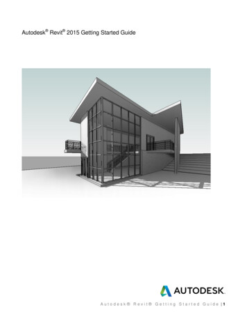
Adding Foundations and Structural Slabs7.2 Isolated FootingsLearning ObjectivesModify the profile of a wall to create step footings.Place isolated footings that are not necessarily connected toany other elements.Load and insert custom footings.Footings are appended to the bottom of a wall, which means thatany change to the base of the host wall influences the footing.This occurs for lateral movement and horizontal movement. Forexample, if the wall profile changes to be based on a hilly site, asshown on the left in Figure 7–10, the footing breaks and followsthe modified profile as shown on the right in Figure 7–10. This isaccomplished by editing the profile of the foundation wall.Figure 7–10If you prefer to have an angled step footing, as shown on the leftin Figure 7–11, you can load a separate isolated foundationfamily that joins with the other foundations as long as thematerials are the same. This is also true for isolated footings asshown on the right in Figure 7–11.Figure 7–11 2013, ASCENT - Center for Technical Knowledge 7–7
Autodesk Revit Structure 2014 FundamentalsHow to:Edit the Profile of a Wall1. Open an elevation or section view in which you can see thewall that you want to edit.2. Select the wall.3. In the Modify Walls tab Mode panel, click(Edit Profile).The wall is outlined in magenta indicating the profile of thewall.4. In the Modify Walls Edit Profile tab Draw panel, use thetools to modify the profile sketch of the wall, as shown on theleft in Figure 7–12.The sketch must form acontinuous loop. Verifythat the lines are cleanwithout any gaps oroverlaps. Use any of thetools in the Modify panelto clean up the sketch.Figure 7–125. Once the profile is complete, click(Finish Edit Mode) inthe Mode panel. The footing now follows the new profile asshown on the right in Figure 7–12.6. Press Esc or click7–8(Modify) to clear the selection. 2013, ASCENT - Center for Technical Knowledge
Adding Foundations and Structural SlabsHow to:Place an Isolated Footing1. Open a plan view at the height at which you want to place thefooting, such as a T.O. Footing structural floor plan.2. In the Structure tab Foundation panel, click(Isolated) tostart the Structural Foundation: Isolated command.3. In the Type Selector, select a footing type.4. In the drawing, click to place the individual footing as shownin Figure 7–13.If you click on a columnto place an individualfooting, the footingautomatically attachesto the bottom of thecolumn. This is trueeven when the bottomof the column is on alower level than the planview you are working in.Figure 7–135. To add more than one footing at a time, in the Modify PlaceIsolated Foundation tab Multiple panel, selector(At Grids)(At Columns) and select the grids or columns.6. Press Esc or(Modify) to end the command. If the material of the wall footing and the material of theisolated footing are the same they automatically join, asshown in Figure 7–14.Figure 7–14 An isolated footing attaches itself to the bottom of thecomponent. Instead of adding extra levels for foundations, you can placefoundation elements at the lowest floor level and then changethe Base Offset parameter for the columns and walls to lowerthe footing below the floor. The foundation elements movewith the base of the walls and columns. 2013, ASCENT - Center for Technical Knowledge 7–9
Autodesk Revit Structure 2014 FundamentalsWorkingwith CustomFamiliesSometimes you need to work with a custom family created fromwithin your company that has parameters that you canmanipulate to fit a specific situation. For example, to add the stepfootings shown in Figure 7–15 you need to insert an angledisolated footing and modify it to fit the exact size.Figure 7–15How to:Load, Insert, and Modify a Custom Footing1. Open a plan view.2. In the Structure tab Foundation panel, click(Isolated)and in the Modify Place Isolated Foundation tab Modepanel, click(Load Family).3. In the Load Family dialog box, find the footing family that youwant to use and click.4. Place the footing in the plan. It might not be in exactly theright place but you can modify it in other views.5. Open an elevation or section view.6. Move the footing to the correct location. As long as it is in linewith another footing it automatically cleans up as shown inFigure 7–16.Figure 7–167–10 2013, ASCENT - Center for Technical Knowledge
Adding Foundations and Structural Slabs You can use(Align) to align footing with the footingalready placed. When it is aligned, select the lock as shownin Figure 7–17 to ensure that if the elevation of the wallfooting changes, the step footing also adjusts appropriately.Figure 7–17 Some custom families have sizing options in either Properties(per instance) or in the Type Properties as shown inFigure 7–18 so that you can create additional types in varioussizes as needed in the project.Figure 7–18 2013, ASCENT - Center for Technical Knowledge 7–11
Autodesk Revit Structure 2014 Fundamentals7.3 Piers and PilastersLearning ObjectiveCreate custom column sizes.The Autodesk Revit Structure software does not have specificcategories for piers and pilasters. If you need to create theseelements, the best method is to use concrete columns as shownin Figure 7–19. You can then analyze them as part of thefoundation system and independently schedule them from themain steel column schedule. A concrete column alsoautomatically embeds itself into a concrete wall.Figure 7–19How to:Create a Custom Column Size1. Open a plan view.2. In the Structure tab Structure panel, click(Column).3. In the Type Selector, select an existing column family typesimilar to the one you want to create, such asConcrete-Rectangular-Column.4. Click(Edit Type).5. In the Type Properties dialog box, click7–12. 2013, ASCENT - Center for Technical Knowledge
Adding Foundations and Structural Slabs6. In the Name dialog box, type a name as shown inFigure 7–20.Figure 7–207. Modify the dimensions as needed. Enter the required valuesfor b (base) and h (height), as shown in Figure 7–21.Figure 7–218. Click.9. The new column is now ready to use. The new pier columnsare placed at the base of the existing columns as shown inFigure 7–22.Figure 7–22 2013, ASCENT - Center for Technical Knowledge 7–13
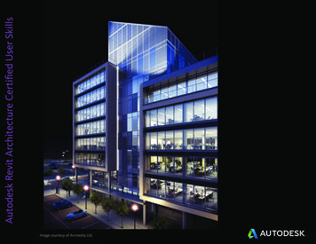
Autodesk Revit Structure 2014 Fundamentals7.4 Creating Structural SlabsLearning ObjectivesCreate slabs for foundations, structural floors, and roofs.Add slab edges.Create shaft openings.Part of a foundation system can be a structural slab (slab ongrade), as shown in Figure 7–23. Slabs are system families. Thistype of family resides within the model and cannot be saved to aseparate file like most other families in the software. As a result,slabs have additional properties within the model itself. After youcreate a structural slab you can add and modify the slab edges.You can also create a shaft opening that automatically cuts theslab through which it passes.The term slab in thistopic applies toStructural FoundationSlabs, Structural Floors,and roofs.Figure 7–23 Structural Floors and Foundation Slabs follow the same basicsteps for creating and modifying the elements.How to:Place a Structural Slab for Foundations or Floors1. In the Structure tab Foundation panel, clickthe Structure tab Structure panel, expand(Slab) or in(Floor) andclick(Floor: Structural).2. In the Type Selector, select the slab or floor type you want touse.7–14 2013, ASCENT - Center for Technical Knowledge
Adding Foundations and Structural Slabs3. In the Modify Create Floor Boundary tab Draw panel, usethe following options to create a closed boundary: Use the Draw tools, such as(Line) or(PickLines) when the slab is not defined by walls or a structureand is free-floatingBoundaries created byPick Walls andPick Supports ensurethat the slab adjusts ifthe footprint of thebuilding changes. Use(Pick Walls) when walls define the perimeter Use(Pick Supports) and select structural walls orbeams when the slab is supported by beams.4. Click(Span Direction) to modify the direction for floorspans. It comes in automatically when you place the firstboundary line, as shown in Figure 7–24.5.(Flip) switches the inside/outside status of the boundarylocation if you have a wall selected, as shown in Figure 7–24.Span DirectionSymbolFlip ControlFigure 7–246. In the Modify Create Floor Boundary tab Mode panel, click(Finish Edit Mode).7. Click(Modify) to release the selection. While placing the floor boundary sketches, you can set anoffset in the Options Bar, which places the sketched line at adistance offset from a selected wall or sketched line. If you are using(Pick Walls), the Extend into wall (tocore) option is also available in the Options Bar. Use this ifyou want the floor to cut into the wall. For example, the floorwould cut through the gypsum wall board and the air spacebut would stop at a core layer such as CMU. 2013, ASCENT - Center for Technical Knowledge 7–15
Autodesk Revit Structure 2014 Fundamentals If you select one of the boundary sketches, you can also setCantilevers for Concrete or Steel, as shown in Figure 7–25.Figure 7–25 Each line that defines the perimeter of the slab has its ownset of properties. This is because different sides of thebuilding can have different slab edge conditions. Setting acantilever can control the detail as shown in Figure 7–26.Figure 7–26 If you specify a cantilever, such as the example shown inFigure 7–27, both the magenta line for the analytical slabedge and the black line for the actual slab edge display. Thisaffects how the decking is terminated.Figure 7–27 This does not add a pour stop or edge angle. You can do soafter you finish the sketch. To create an opening inside the sketch, create a separateclosed loop inside the first sketch, as shown in Figure 7–28.7–16 2013, ASCENT - Center for Technical Knowledge
Adding Foundations and Structural SlabsFigure 7–28 If there are any walls below the slab, an alert box opens asshown in
Autodesk Revit Structure 2014 Fundamentals www.SDCpublications.com SDC Better Textbooks. Lower Prices. PUBLICATIONS