Transcription
Do-It-YourselfSprinkler Planning& Installation GuideYour beautiful landscape awaits.
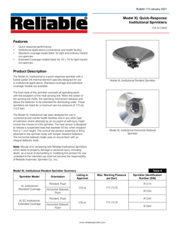
IntroductionDo-It-YourselfSprinkler Planning& Installation GuideTable of ContentsBefore You Begin . . . . . . . . . . . . . . . . . . . . . . . 1Using the Toro Design Service . . . . . . . . . . . 4Questionnaire . . . . . . . . . . . . . . . . . . . . . . . . . . 5Property Plan Layout Sheet . . . . . . . . . . . . . 6 Traditional Irrigation Installation . . . 1-12Two Systems Are Better Than OneCongratulations on your decision to install an automaticirrigation system. An automatic irrigation system will help youcreate the landscape you’ve always wanted by making sureyour plants get the water they need, just when they need it.How many times have you forgotten to water your lawn, orworse yet, over-watered it and ended up with unsightly brownspots and muddy puddles? You could be using up to 50%more water than your yard needs. That isn’t good for your lawnor your pocketbook. The solution is precision watering usingan automatic irrigation system which can be adjusted to theindividual needs of different plantings. You will get a thicker,greener lawn and more beautiful gardens, as you save timeand water.STEP 1 - Gather Required Information . . . . . . . 2STEP 2 - Map Out Your System . . . . . . . . . . . . 7%#STEP 3 - Install It! . . . . . . . . . . . . . . . . . . . . . . 9Troubleshooting . . . . . . . . . . . . . . . . . . . . . . 13Appendix A-E . . . . . . . . . . . . . . . . . . . . . . . . . 14-16Frequently Asked Questions . . . . . . . . . . . 18Irrigation Installation Tips . . . . . . . . . . . . 19An example of traditional sprinkler-based and drip irrigationsystems. This system uses automatic in-line valves.There are two different styles of irrigation systems you canuse: traditional sprinkler-based systems and drip irrigationsystems. The good news is you don’t have to choose betweenthem because they work better together. This is an instancewhere two really are better than one.Traditional sprinkler-based systems are well suited towatering large areas of grass and areas with plants havingsimilar watering needs. They water uniformly by broadcastingwater in well defined patterns, five feet or more in diameter.To water smaller areas, we recommend drip irrigation.Drip irrigation is the ideal complement to traditional irrigation.Rather than broadcasting water over large areas, a drip systemis set up to water very small, specific areas. For that reason, dripsystems are good for patios, near foundation walls, wateringspecific plants within larger garden areas and tight, slowdraining clay soils. In so doing, drip systems use little waterand discourage weed growth. (For details on drip irrigationand planning, refer to the Toro Blue Stripe Drip Planning &Installation Guide.)So, in order to create the best irrigation system possible foryour plants, don’t think in terms of traditional or drip; think interms of traditional and drip. You get the best of both worldsand the very best results.842!
Getting StartedBefore You beginBeginning Your DesignThere is no question that planning and installing an irrigationsystem is a big job, but it is not a difficult one. To make it easier,we have divided the process into just three steps that walkyou through the job from beginning to end. They are: GatherRequired Information, Map Out Your System and Install It.There are two options for getting a design for yourautomatic irrigation system:1. Follow the instructions in this guide and use the layout paperon page 6 to design and draw your irrigation system.OR,Remember, we’re here to help you.Visit www.toro.com or www.torodesign.comor call 800-367-8676.2. Let Toro do the irrigation system design for you!See page 4 for more information on Toro’sSprinkler Design Service.In either case, you will need to complete sections A - D. Wesuggest you use the following planning tools: pencil, scratchpaper, drawing compass, 50’ tape measure, straight edge orruler, line marking paint for marking trenches, Toro flags formarking sprinkler locations and a Toro Flow & Pressure Gauge.Check Local Codes and PermitRequirementsBefore beginning your irrigation project, contact yourlocal water company or the proper municipal authority forinformation on building codes and required permits. They canalso tell you about requirements for the backflow preventiondevices required in your area. These devices protect your watersupply from contamination and are required for ingroundirrigation systems.Warning! Serious injury may result from damagingburied electrical or gas lines. Before digging or trenching, haveyour local utility companies mark all buried cables, pipes, andgas lines! Tools And Other Supplies You May NeedDuring installation, you will need several accessories anda variety of pipe fittings. The list below shows materialsyou may need: PVC pipe cutterScrewdriverPipe wrenchesHammerTrenching shovelLine marking paint1” pipe clamps (poly only)PTFE tapeDuct tapeTape measureSolvent, primer, rags (PVC only — do notuse pipe dope on plastic-threaded fittings.)Toro flow and pressure gaugeToro marking flagsToro water-proof connectors or grease caps18 gauge, multi-strand direct burial wire(number of strands varies depending onthe number of zones).Tip:If you do not own a flow & pressure gauge, ask your localhome center if they have one in their rental center.ADraw Your PropertyUse the layout paper provided on page 6 of this guide.Each small square on the graph should represent one squarefoot of actual property or use a scale such as 1 inch 10 feet,1 inch 20 feet, etc. Using the tape measure, measure yourproperty and draw it to scale on the layout paper. Use thedrawing below as an example.WaterMeterRemember: Outline your house, garage, and other structures.Show walkways, drives, slabs, patios, and other surfaces.Identify trees and major obstacles.Measure and record the perimeter of your property.Identify any slopes.Show groundcover, grass, flower beds and landscaping.Identify the size and location of thewater meter (or pump) and main line. Identify the type of soil in your yard: sand, loam, or clay.Tip:Be sure to doublecheck all measurements.1
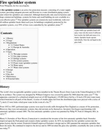
Step 1 - Gather Required InformationBCDeterminE Your soil typeThere is a simple way to determine what type of soil – sand,loam, or clay - you have in your yard. All you need is aclean, empty jar with a lid, some clean water, a tablespoon ofdetergent, and a sample of the soil you want to test. To do so: Fill the jar about 1/3 full with the soil to be tested. Fill the jar with water and detergent then cap it. Shake the jar vigorously and set asidefor several hours or overnight.EMITTERWhat is the diameter of the water supply line?Length ofStringCopperService LineGalvanizedor PVCDiameter CLAYFor more information on soiltypes and more precise ways toascertain soil composition, youcan refer to: www.yardcare.com.LOAMSANDWetting patterns fordifferent soil types2Once you have the property plan completed, you will need togather some very important information about your property’swater supply system.Call your local water company or, if they can’t help you,measure your supply line (the pipe coming out to meter).Wrap a piece of string around the pipe once and thenmeasure the string. Use the chart below to determinethe supply line diameter.Evaluate the results:A. If the water is clear and thesoil has settled to the bottom,you have predominantly sandsoil.B. If the water is still murky withbits of matter still suspendedin it, you have loam soil.C. If the water is still murky,and there is a visible ring ofsediment around the jar, thenyour soil is mostly clay.Water Service ��-1”-11/4”-/4”-1”-11/4”3-3inches
Gather Required Information - Step 1DWater flow & Pressuredetermine your water pressure & flowYou can use either of the two methods listed:1 Using a TORO flow & pressure gaugeThe Toro Flow and Pressure Gauge is a dual purpose devicedesigned to measure water pressure to 160 PSI and water flowto 13 GPM. This flow and pressure gauge is not intended foruse on lines larger than one inch. The gauge will only measureflow through the outside faucet – not in the line.To measure the static pressure: Make sure no water is being used inside or outside thehome. Attach the flow gauge to the outside faucet nearest towhere the main line enters the house. Make sure the flow gauge is closed by completelyturning the handle clockwise. Open the outside faucet slowly to avoid damagingthe flow gauge. When the outside faucet is fully opened, read thesystem static pressure and record it below.Record the staticsystem pressure here:Static PSI2 Using a bucket & STANDARDpressure gauge Find the outside faucet that is closestto your water supply line.(Call this Faucet 1) Select a different outside faucet onyour house and attach a pressuregauge. (Faucet 2) With Faucet 1 closed, open Faucet 2 all theway and record the static water pressure below. With Faucet 1 open all the way, check thepressure reading on the gauge at Faucet 2.*If it is less than 40 PSI, turn down the water flow fromFaucet 1 until the reading reaches 40 PSI. Place a 5-gallon bucket under Faucet 1 and time how long ittakes to fill it. Use the chart below to convert to GPM. Thistest tells you what your home’s water capacity is measuredin GPM at 40 PSI. Repeat this procedure at 45 PSI and 50 PSI andrecord these three results on the chart below:This is how much water is available with a working pressureof 40 PSI or the higher reading that you recorded. (Minimumoperating pressure for most sprinklers is 35 PSI.)Time To Fill BucketGallons Per Minute15 seconds20 GPM20 seconds15 GPMTo measure the dynamic pressureand gallons-per-minute rates:25 seconds12 GPM30 seconds10 GPM Continue to open the flow gauge slowly by turning thehandle counter-clockwise.*As the flow gauge opens, pressure will drop from the staticreading and the gallons-per-minute (GPM) reading will rise. Open the flow gauge until pressure drops to 50 PSI. Record the gallons-per-minute reading on the chart below. Continue to close the gauge to 45 and 40 PSI and recordthe GPM readings.40 seconds7.5 GPMNote:Static pressure measures the pressure in the system withno water running. It is measured in pounds per square inch or PSI.If the pressure does not drop to 40 PSI after opening the flowgauge all the way then take the flow and pressure reading atthe full-open position. If rapid fluctuation occurs on the flowgauge, record the average reading.Note:Dynamic or working pressure is the pressure in thesystem with the water running. The dynamic pressure willdetermine how far your sprinklers will spray.Record the GPM indicatedon your flow and pressuregauge here:If readings are higher,record here:GPM at 40 PSIGPM at 45 PSIRecord the staticpressure here:Static PSIRecord the GPM here:GPM at 40 PSIGPM at 45 PSIGPM at 50 PSIIf readings are higher,record here:GPM at PSINote: If you use a different size bucket, time how long it takesto fill it. Convert this to GPM using the following formula:60 Seconds x GallonsFor example: A 2-gallon bucket that fills in 15 seconds means theavailable flow is 8 GPM60 15 x 2 8 GPMGPM at 50 PSIGPM at PSI3
Property Plan Layout SheetYour Name: Scale: Inch Feet6
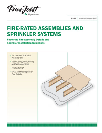
map out the System - Step 2Map out your sprinklersand emitters123Now it’s almost time to draw in your sprinklers on yourirrigation plan. Before you do, be sure to consider thefollowing information: Draw sprinklers within each zone ofyour plan one area at a time. Place sprinklers with the greatest radius in larger areas.*Pay attention to the allowable spacing range for thesprinklers selected to create head-to-head coverage. Always place sprinklers in a way that avoids spraying theside of your house, walls, fences, etc. Also, minimize thewater spraying onto sidewalks, driveways and streets. Place half-circle sprinklers on edges and borders,quarter‑circle sprinklers in corners, and full-circlesprinklers in the middle of spaces. Use rotor or impact sprinklers to cover large areas.They can distribute water up to 48’. Use 570 fan spray sprinklers to cover smaller areas.They are effective up to radii of 15’. Use bubblers or drip irrigation in small confinedareas and to water plants individually. To help in your planning and irrigation component selection,we have included component selection information in theAppendix (pages 14-17) at the end of this manual.Tip:Do not mix fixed-spray and rotors within the same zone.Now it’s time to determine how many zones you will need.A zone is a group of sprinklers that operate together usingone common irrigation valve. Each valve, and thus each zone,is operated by your system’s timer.A1Write down the flow capacity in GPM for each type ofsprinkler in your layout. (see page 17)2Next, divide similar sprinklers into groups. Separate lawn and shrub areas. Separate shady and sunny areas.*Different sprinkler types apply water at different rates so don’tmix sprinkler types within zones. For example, fixed-spraysprinklers should not be grouped with rotary sprinklers.3Add up the sprinkler GPM for each of the zones you havecreated on your plan. If the total flow exceeds the safe designcapacity for your system, split that zone in two, or, if possible,put some of the sprinklers into another zone. Remember tomove sprinklers to other zones based on slope, sun, shadeor GPM.Count Your ZonesCount up the number of zones you have in your design. Thatis the number of irrigation valves you will need. In the exampleon page 8, we will need eight valves because we have eightzones. This will also affect the size timer you will need to buy.Layout the Valves on your PlanWe recommend grouping the valves together. For example,grouping all the valves needed to operate the front yard zonestogether. This symbolrepresents a valve location.Incorrect head-to-head spacingDetermine the correct spacing using the sprinkler radius. Forexample, if you are using Toro 570 sprinklers with a radiusof 15’, place your sprinklers no more than 15’ apart - closertogether if you are in a windy area.Full CircleBCCorrect head-to-head spacingDivide Your SystemTo determine the number of zones you need in your system,do the following:Head-to-Head CoverageFor proper coverage, layout your sprinkler heads so that thespray from one reaches all those adjacent to it. Head-to-headcoverage ensures uniform water application, which saves waterand creates the best possible results. (Refer to diagram.) Forareas with winds regularly above 8 mph, place sprinklers closertogether — 90% of the spray radius or less depending on theprevailing wind direction and speed.Create Your Zones15’ RadiusHalf CircleLocate the first set of valves in a convenient spot near the mainwater connection. A good idea is to place valves next to walksor in planters for easier access.The example on the next page shows two valve manifoldlocations. The front valve manifold controls zones 1, 2, 3 and 4.The backyard valve manifold controls zones 5, 6, 7 and 8.It is recommended that the timer be able to control morevalves than are called for in your plan. This will make any futureexpansion much easier. The Toro ECXTRA expandable timerwould be ideal to use in this example.Quarter CircleTip:To make sure you have proper head-to-head spacing,use a compass to draw arcs representing sprinkler coverage,as shown in the diagram.7
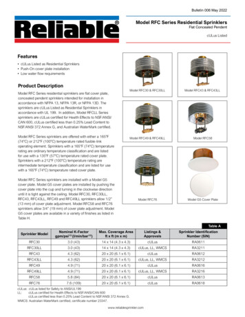
Step 2 - Map Out the SystemDEDRAW IN the PipesUse the following symbols to layout your irrigation pipes:Main line from the water source to the valvesFrom the valves to the sprinkler heads(shown only for zones 1 and 4)Under driveway and walkwaysWhen laying out your irrigation linesobserve the following guidelines: Use as many straight runs as possible.Try to avoid turns, which result in loss of pressure.Avoid runs under sidewalks and driveways whenever possible.Make 90 degree connections wherever possible.Note:You can include more than one pipe in a trench.Depending on local codes and zone GPM , consider using 1”Schedule 40 PVC pipe upstream of control valves and at least3 4” Class 200 PVC pipe or 3 4” poly pipe downstream.Draw in the location of the timerInstall the timer inside your garage or on an outside wall neara 120 VAC outlet. Toro offers a weather-resistant timer cabinetfor mounting in exterior locations. Toro also offers an ECXTRA expandable timer with an integrated all-weather enclosureto make mounting in exterior locations easier. Check localelectrical codes for connection requirement to outside plugs.Use this symbolto reflect the timer location.Place zone or valve wires in the same trenches as the pipe.Remember that the valves will be wired to the timer, so runthe valve wires where they will be easily accessible. Tororecommends 18-gauge, multi-strand, direct-burial wire toconnect valves to sprinkler timers if the distance is 1000 feetor less (refer to Timer to Valve wire sizing chart on page 18).You will need one wire per zone, plus the common wire. Forinstance, this eight-zone system requires nine wires. Be sure touse Toro’s Waterproof Connection Caps or grease caps for allyour waterproof connections.Tip:Always install 2 or more wires than valvesto make it easier to add more valves in the future. Using the GPM Rate toChoose the Correct PipeZone 3Zone 132Zone 2/4” Schedule 408 GPM13 GPM3/4” Class 20010 GPM1” Class 20015 GPM78Zone 3Zone 5Zone 6Max. GPM1” Schedule 40361Maximum Flow throughPVC (Plastic) Pipe:PVC Pipe Size54Planter AreaFlow Rates for ServiceLines & Sprinkler LinesZone 4Zone 2Grass StripTo determine the proper pipe size foryour system, refer to the chart below.TimerZone 8Zone 7Zone 6Side LawnMaximum Flow throughNew Galvanized Pipe:Galvanized Pipe Size Max. GPM/4” Galvanized Pipe8 GPM1” Galvanized Pipe13 GPM3Key:Zone ValveMaximum Flow throughType K Copper Pipe:Copper Pipe SizeMax. GPM/4” Copper Tube6 GPM1” Copper Tube12 GPM3Maximum Flow throughPolyethylene Pipe:Poly Pipe SizeMax. GPM/4” Poly Pipe8 GPM1” Poly Pipe13 GPM38TimerSprinkler HeadWater MeterNote:In freezing areas,poly pipe should beused downstream ofzone valves.A correct pipingsystem withstraight runs.An incorrect piping systemwith too many turns in thepipe results in reduced flowand pressure to the lastsprinkler on the line.
Install It! - Step 3Check Local Codes and PermitsDouble check to ensure you have secured all permits. Inaddition, have the local utilities mark all the buried lines andpipes before you start digging.In most areas, dialing 811 will get your utilities marked.Otherwise contact yourlocal utility provider(s).AMark your sprinklers, risers,valves & trenchesUse Toro flags to indicate sprinkler locations according to yourdesign. Also, mark the location of your drip system risers. Evenif you plan to install the actual drip system at a later date, youcan install your drip risers with the rest of your system.Use line‑marking spray paint to mark where you’ll trench forpipes and wiring. Check your worksheet to make sure you markthe lines accurately. You will be digging your trenches alongthese lines.BTap into Your Main Water LineBy cutting into your service line and slipping on a compressiontee, you can connect your sprinkler system to the watersupply without soldering. In some instances, you can avoidcutting the main line by attaching your system to the outsidefaucet connection (see diagram and note). PVC pipe may besubstituted for copper in non-freezing areas.1 Shut-Off ValvesTypical installation if the meter is in your yard2 If the Meter Is in Your Yard:1. Shut off your water supply at the meter(check with your water department first).2. Dig to expose the service line.3. Tie into the service line, between the water meterand the house.4. Remove a section of pipe, leaving a gap large enoughto slide on a compression tee.5. Slip the tee over each end of the pipe.6. Tighten the compression nuts. The rubber gasket willcompress against the pipe, creating a seal to prevent leakage.7. Install a short nipple, using PTFE tape on all threadedconnections to the tee.8. Attach a shut-off valve, in a small enclosure, to this sectionof pipe. The shut-off valve allows you to turn off the systemby hand, if necessary.9. Keep this connection as clean as possible.This is your tap water supply.06""ASEMENTCEILINGWhether a Pressure Vacuum Breaker (PVB) is used or not,we recommend installing a shut‑off valve between the zonevalves and the service line. This will allow you to easily turn offthe water to your irrigation system if you need to make repairsor replace parts. Check local codes for the type of shut-off valverecommended.3EVICE LINETO HOUSE 4HREADED 4EEW DRAIN VALVE USEDAS 7INTERIZATIONBLOWOUT PORT RAINVALVE4O VALVE MANIFOLD7ATER METER3HUT OFFBALLVALVE"ELOW GROUND3ERVICE LINE FROM STREET"ASEMENT FLOORTypical installation if the meter is in your basement3 If the Meter Is in Your Basement:Typical installation from a faucetCold Climates: If you live in an area where it gets belowfreezing, it’s best to winterize your system in the fall.To make it easier to attach the air line to blow outyour system, add a tee in the main supply line (S x S x T)between the PVB and the valve manifold, screw a cap onthe extra leg.1. Shut off your water supply at the meter(check with your water utility).2. Install an appropriate tee into the service linefor the irrigation connection.3. Drill a hole through the sill above the foundation, or chisela hole in the basement wall for the irrigation line to runthrough. Make it no bigger than needed for a 1” pipe.4. Install the connection fittings, as shown. A ball valve is agood choice for the irrigation shut-off. For the drain valve,use a gate-type valve. The drain valve should be as low aspossible to allow complete system drainage.5. Feed your irrigation system pipe out throughthe basement wall, and run it to the backflowpreventer location.6. Finally, seal the hole in the sill orfoundation with caulking compound.9
Step 3 - Install It!CMain and Lateral Line TrenchingThe main irrigation line is the pipe that runs from your serviceline to your valve manifolds. The lateral lines are the lines thatrun from the valve manifolds to the sprinkler heads.1 Trenching by HandTo soften the soil, water the ground approximately two daysbefore you dig. Dig trenches 8” to 12” inches deep. Put sod onone side of the trench and soil on the other.DInstall the IrrigationSystem Main LineAttach the main sprinkler line to the service line. Run it alongthe bottom of the trench from the house to the first set ofvalves, and if required, to the second set. Place the valve wiresunder the pipe in the bottom of the trench whenever possible.1 Working With PVC Pipe1. Cut pipe with a PVC pipe cutter.2. Brush on a primer to clean the pipesurface and the inside of the fitting.3. Brush glue on the outside end ofthe pipe and lightly inside the fitting.4. Slip the pipe into the fitting and give it a quarter turn.5. Hold in place for about 15 seconds so the glue can set.6. Wipe off excess glue with a rag.Warning! Before digging any trenches, you must haveall underground utilities marked to avoid any damage. Call your localunderground locator service, or the city for information, or dial 811.2 Trenching using a TrencherTrenching machines are an easier, faster alternative to diggingwith a shovel. They can be rented by the hour, day or week,usually from a lawn supply store or rental equipment dealer.The person you rent from can show you how to operate themachine properly and safely. Trenchers should not be usedto dig through ground cover, flower beds, on steep slopes ornear buildings. Be sure to verify all underground utilities beforetrenching.In colderclimates avibratory plowis used forpulling pipe.Note: Wait at least one hour before running water throughthe system. (Check manufacturer’s recommendation.)2 Working With Poly Pipe1. Cut pipe with a PVC pipe cutter.2. Slip a stainless-steel clamp over the end of the pipe.3. Insert the barbed fitting into the end of thepoly pipe, past the barbs.4. Slide the clamp over the barbs of the fitting.5. Tighten the clamp.Self-tappingSaddle (53686)TIP:Save time by using the Toro Self-Tapping Saddle for polypipe (80-100 PSI). No more sawing, drilling or gluing! SelfTapping Saddles are available at your local home center.TIP:To relax poly pipe, expose it to sunlight.Never expose poly pipe to open flame.Warning! Do not use poly pipe as the connecting pipebetween the service line and the control valves. Surge pressuremay rupture the poly pipe. Be sure to check local codes for correcttype of pipe to use.Do it the easy way, use the ToroDingo with Trenching Attachment10
Install It! - Step 3EFBuild valve manifoldsStart from the valves and move outward, laying the connectingpipe along the bottom of the trench (more than one pipe maybe laid in a trench). At each flag, install a tee or elbow fitting,and if needed, a riser for sprinkler attachment. We recommendthat you use Toro Funny Pipe for all your sprinkler headinstallations. Refer to the Funny Pipe section for moreinformation.A group of valves running off the same supply line is called amanifold. We recommend grouping your valves into manifoldsbased on their use or location. For example, one control valvemanifold to operate front yard zones and one to operatebackyard and/or side yard zones. Use flags to mark thelocation of the valves, as indicated on your worksheet.Refer to the valve inlet size chart on this pagefor general valve inlet size rule of thumb. Ì - « Ê6 ÛiÃÊÃ Õ ÊLiÊ ÃÌ i ÊÈ ÊÌ Ê Ó Ê L ÛiÊÌ iÊ } iÃÌÊëÀ iÀÊ ÀÊ VV À }ÊÌ ÊV i * « Õ«-«À iÀGFlush the System to Clear DebrisAfter the pipe has been connected and the glue has dried (PVCpipe only), turn on the water, open valves one zone at a timeand flush until the water runs clear. Seal the fitting with ducttape to keep dirt out until the sprinklers are installed./ Ê iÝÌÊ v ÊÝÊÎÉ{ Ê «ÌiÀ/ À Ê Õ ÞÊ* «iÊ Ê ÌÌ }ÃInstall Lateral PipeÎÉ{ ÊÝÊÎÉ{ Ê «ÌiÀNote: Don’t backfill your trenches untilyour final system operation check is complete.ÎÉ{ Ê- «ÊÝÊ- «ÝÊ- «Ê/iiÎÉ{ Ê- i-«À iÀÊ ÌiÀ Ê iÎÉ{ Ê ÃÃÊÓääÊ*6 Ê iÊvÀ Ê iÌiÀ Ê-V i Õ iÊ{äÊ*6 Ê- «ÊÝÊ- «ÊÝÊ- «Ê/iivalve installation1 Anti-siphonAnti-siphon valves are backflow prevention valves designedto protect your water supply from contamination. Some sortof backflow prevention is required on every irrigation system,so you need to check the building codes in your area to findout if an anti-siphon valve will work for you. These valves arealways installed above ground, so be sure to dig out an arealarge enough to accommodate your inlet and outlet pipes.1”Schedule40 PVCPressure Vacuum Breakershould be installed12” above the highestsprinkler, or according tolocal codes.Install Your SprinklersZone-by-ZoneHInstall one sprinkler zone at a time, using Toro Funny Pipe to connect to the lateral lines. Remember to refer to yourplanning worksheet.1. Placing a sprinkler in a trench as a guide, measure from theconnecting pipe fitting to the bottom of the sprinkler andcut a length of Funny Pipe to fit. Place sprinklers at least 3”from sidewalks and curbs and 6” from fences and buildings.2. Install the appropriate Funny Pipe elbow into thesprinkler and into the PVC or poly pipe fitting.No glue or clamps needed.3. Connect the Funny Pipe to the sprinklerand to the pipe fitting.Note: Do not use more than 4’ ofToro Funny Pipe with each sprinkler head. 4” Class200 PVC31” Schedule40 PVCfromwatersourceValveBox1” Slip x Slip xThread Tee1” NPT x 4” SlipFemale Adapter34. Position the sprinkler in the trench so that the top of thesprinkler is flush with ground level. Stabilize the sprinklerwith soil without filling the entire trench.5. Verify that the sprinkler is vertical for optimum performance.6. Repeat this process for each sprinkler.2 In-line valve installationIn-line valves are installed below ground and should alwaysbe installed in a protective valve box. Dig out the area wherein‑ground valves are to be installed, and add several inches ofgravel to the bottom of the hole. Place the top of the valvebox so that it is even with the surface of the ground. Whenyou buy a valve box, be sure to find out how many valves fitin each box so you know how many to buy. In some cases,you will need more than one valve box per manifold.Note: If one of the valves will be used for drip irrigation, leaveenough room between the valve and the sides of the valve box forthe filter and pressure regulator that are part of your drip system.It may be a good idea to install those parts on the valve, then,install the valve in the valve box.Tip:When putting together your valve manifolds, alwaysinclude one or two extra connections in each manifold. Thismakes it easier to expand your system at a later date.Tip:Look for valves with the flow control feature.It saves water!Valve Inlet SizeSize of InletGallons Per Minute (GPM)3/4”Under 8 GPM1”Above 8 GPM11
TroubleshootingMalfunctions aren’t common, but when they occur, they’re often due to one of these causes.Refer to each product’s specific operating manual for additional information.TIMERSPROBLEMWatering cyclerepeatsFuses blowregularlyLED display isblankLawn is notwateredVALVESCAUSESOLUTIONMultiple start times setCheck program and turnoff all but one start timeSeason adjust is set atmore than 100%PROBLEMTurn supply valve onReset Season AdjustFaulty valve solenoidReplace solenoidFaulty valve solenoidReplace solenoidFlow control at valve isclosedOpen fullycounterclockwiseDamaged or shortedwiringInspect and repair wireZone valve wires notconnectedConnect wiresFaulty timerReplace timerNo power to timerCheck outlet for powerDebris in valve, solenoidor metering orificeDisassemble valve andclean with fresh waterFaulty transformerReplace transformerFaulty v
A Draw Your ProPerTY Use the layout paper provided on page 6 of this guide. Each small square on the graph should represent one square foot of actual property or use a scale such as 1 inch 10 feet,