Transcription
Road Rehabilitation and Reconstruction Using AutoCAD Civil 3D
Road Rehabilitation and Reconstruction Using AUTOCAD CIVIL 3D ContentsIntroduction . 3Introduction to Corridor Targets . 3Surface Targets . 4Width and Offset Targets . 5Elevation or Slope Targets . 5Conditional Subassemblies . 6Design Examples . 7Example 1: Mill and Overlay . 7Example 2: Three-Inch Minimum Overlay . 10Example 3: Superelevated Highway Reconstruction . 12Example 4: Overlay and Widening to Create a Turning Lane . 17Example 5: Driveway Curb Cuts . 21Using the Corridor Section Editor . 23Additional Corridor Sections . 23Profile Smoothing . 24Using Code Set Styles . 24Creating Section Views. 25Conclusion . 262
Road Rehabilitation and Reconstruction Using AUTOCAD CIVIL 3D IntroductionFrom an engineering standpoint, road reconstruction is often considered the most difficult type of road design to perform.Rather than dealing with the pristine geometry of new construction, the designer is faced with integrating the design intothe irregularities of existing conditions. Because of this, each cross section of the road often requires an individualdesign, with special attention to cross slopes, pavement irregularities, and many other potential conditions. Despite thesechallenges, the designer is required to produce an accurate account of the required material types and quantities. Thiswhite paper can help you obtain the technical foundation needed to perform various types of road rehabilitation and reconstruction design with the help of AutoCAD Civil 3D software.In this document, we will begin by exploring the concept of corridor targets. AutoCAD Civil 3D comes equipped withsubassemblies designed specifically for road rehabilitation and reconstruction design, as well as the capability tocustomize subassemblies using Subassembly Composer.What makes subassemblies more uniquely suited for rehabilitation and reconstruction projects is their ability to interactwith and analyze existing conditions, and respond in ways that better suit the design intent. In this way, the designerdoes not have to approach each cross section as an individual design, but instead can configure these subassemblies tomake design decisions automatically. The result is that with the help of Civil 3D, road reconstruction design can be donein about the same amount of time as new construction design.In this white paper, we use five examples to examine the process of designing a road reconstruction or rehabilitationproject, outlining how to address specific design scenarios and passing along valuable information about specificfunctionality within certain subassemblies, the need and ability to create custom subassemblies, as well as corridorfunctionality. After these examples, you will learn a few recommended procedures and techniques to help finalize thedesign, address some minor design issues, and control the visibility of design components through codes and codesets. Next, we will examine the process of generating cross-section data and section views to begin assembling thenecessary information for construction documentation. This paper will conclude with a brief review of the key corridorconcepts and summarize the theory behind subassemblies.Introduction to Corridor TargetsBefore discussing road rehabilitation and reconstruction specifically, it is important to understand the key concept ofcorridor targets. One way of describing a corridor target is that it is a way for the corridor to interact with and respond toother objects in the drawing. Through the subassemblies parameters, corridors have the ability to target surfaces,alignments, profiles, feature lines, pipe networks, polylines, and survey figures. Corridors can be designed toautomatically tie embankments to a surface, widen a lane along an alignment, match a ditch invert to a profile, andaccommodate many other design scenarios. Generally speaking, targets are used when the geometry of the corridorneeds to change as the design progresses along the baseline.To find information about the targeting capabilities of a subassembly, you can select it in the Subassembly Referencetopic of the AutoCAD Civil 3D Help and read the section entitled Target Parameters. The capabilities and parametertables of each subassembly can be accessed through the contextual user interface when the subassembly object isselected.Corridor targets fall into three basic categories: surface targets; width and offset targets; and elevation or slope targets.Civil 3D also provides for conditional subassemblies, which automatically add specified subassemblies with definedtargets to an assembly when specified vertical or horizontal conditions are encountered along the corridor.
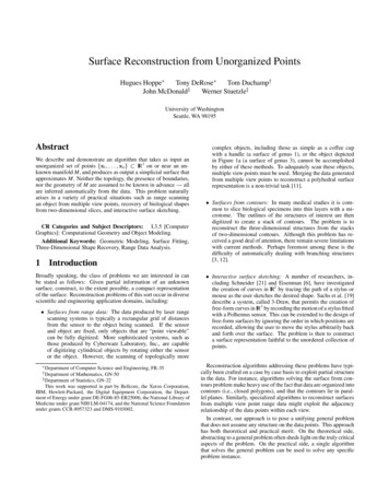
Road Rehabilitation and Reconstruction Using AUTOCAD CIVIL 3D Surface TargetsA surface target refers to a surface object that the corridor model will react to. For road rehabilitation projects, the surfacetypically models the existing roadway and its surrounding terrain. The most common application of a surface target isfound in the daylight subassemblies. The primary function of these subassemblies is to seek out a surface and intersectwith it while considering certain requirements, such as slope, offset, or elevation. One of the simplest daylightsubassemblies that utilizes a surface target is LinkOffsetOnSurface. This subassembly is typically attached to the outeredge of a shoulder. From that point, it will intersect with a surface at a specified offset from the corridor baseline. Since itis tied to an offset location, the slope will vary as it finds each intersection point.Figure 1: Schematic diagram of the LinkOffsetOnSurface subassembly.Figure 1A: The LinkOffsetOnSurface subassembly shown in cross section. In this corridor model, the LinkOffsetOnSurfaceoffset parameter was set to 40'. The cross section shows how the subassembly ties into existing ground 40' from the roadcenterline, adjusting its slope accordingly.Many more daylight subassemblies are available for modeling ditches, benching, different soil materials, and otherdesign components. They have one characteristic in common—they target a surface.Rehabilitation and reconstruction projects require the use ofsubassemblies that target a surface, but not for daylightingpurposes. The OverlayWidenMatchSlope1 subassembly,for example, will analyze the surface of an existing road tohelp calculate its cross slope. It does this by sampling theFigure 2A: Civil 3D reads the elevation of the targetsurface at two key points and calculating the slope betweensurface at the Sample Point and Insert Point to helpthem. The sample point tells the subassembly where to makedetermine the existing cross slope.its first reading of the target surface elevation. The insert pointtakes a second reading of the target surface elevation. Thesubassembly then calculates the difference between these two elevations to come up with the existing road cross slope.When the additional lanes are added for the new widening, they will use this slope to create a continuous cross slope.
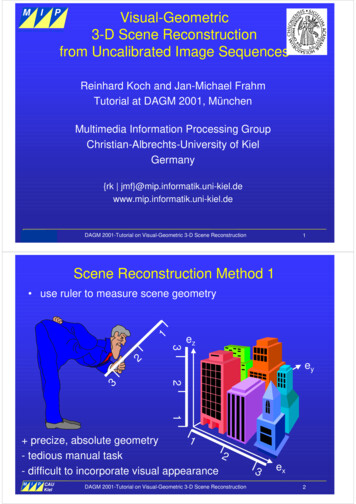
Road Rehabilitation and Reconstruction Using AUTOCAD CIVIL 3D Figure 2B: Once Civil 3D has determined the existing cross slope, the OverlayWidenMatchSlope1 subassembly models anoverlay of the existing lane(s) and creates new lane(s) to the design specifications.The OverlayWidenMatchSlope2 subassembly works similarly to the OverlayWidenMatchSlope1 subassembly, exceptit builds both sides of the road centerline.Width and Offset TargetsWidth and offset targets are used to define a changing horizontallocation of a key point on a subassembly; the offset target as itrelates to the baseline alignment, and a width target as it relatesto another point on the subassembly. The most common exampleof using an assembly with both a width and an offset target iswidening a road in order to help meet current standards. TheOverlayWidenMatchSlope1 subassembly (Figure 2B) has theability to target an alignment, feature line, polyline, or surveyfigure to define the width value of the new roadway. When thelane width target, such as the Edge of Travel Way, is assigned,the edge of the subassembly becomes attached to the targetobject and will widen or narrow (Figure 3) to maintain that matchto that location. In addition, the sample point and insert point inthe OverlayWidenMatchSlope1 subassembly can each beassigned an offset target, thus controlling the location of thesepoints at specific locations along the corridor.Edge of Travel WayCenterlineFigure 3: Specific subassemblies can use alignments,profiles, polylines, feature lines, or survey figures astargets to control the shape of the corridor.Elevation or Slope TargetsAn elevation or slope target is used to define a changing vertical location of a key point on a subassembly as it relates tothe baseline profile or another point on the subassembly. An elevation or slope target can be a profile, feature line, 3Dpolyline, or survey figure. One example of using an elevation or slope target is the use of a profile to define the invertelevations of a roadside ditch, where the road and the ditch each follow an individual profile, causing the verticaldifference between the ditch invert and road centerline to differ as the design progresses along the baseline. In this way,the slope of the ditch can be controlled for drainage purposes while the slope of the road is controlled independently.Another example of using an elevation or slope target can be found when the OverlayCrownBetweenEdgessubassembly is used (Figure 4). By using this subassembly, the elevations of the left edge point and right edge point canbe controlled via an elevation target. This target is commonly a survey figure representing the existing edge of pavement,defined as a result of a topographic route survey processed in Civil 3D using the tools provided in the Survey Toolspaceand Survey tab. Of course, any other suitable elevation target, such as a profile, feature line, or 3D polyline could also beused.
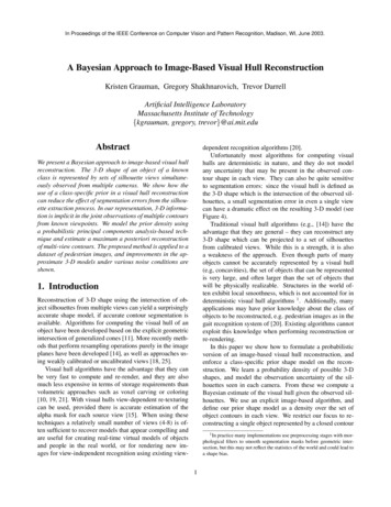
Road Rehabilitation and Reconstruction Using AUTOCAD CIVIL 3D Figure 4: Schematic diagram of the OverlayCrownBetweenEdges subassembly. The Left Edge Point and Right Edge Point canbe tied to an elevation target—such as the survey figure of the existing edge of pavement.Conditional SubassembliesConditional subassemblies are special types of subassemblies that provide a means of conditional target control. Theyautomatically add specified subassemblies to an assembly when certain conditions, which you specify, exist. Oneexample is the ConditionalCutOrFill subassembly (Figure 5). It can be used to analyze the station, offset, and elevationposition of the subassembly, based on the parameters you specify, and then automatically apply different subassemblies,such as daylighting, ditching, and retaining walls, based on whether the subassembly is in a cut or fill condition.Figure 5: Schematic diagram of a ConditionalCutOrFill subassembly. This shows a configuration to automatically add a benchsubassembly on the left and a ditch on the right when Civil 3D detects that the assembly is in a cut condition, andautomatically add a shoulder and grade to either side when a fill condition is detected.The other type of conditional subassembly is the ConditionalHorizontalTarget subassembly (Figure 6). Thissubassembly performs analysis at each station in order to help determine whether an offset target exists within aspecified distance and automatically adds various subassemblies, such as widening, curb and gutter, ditching, ordaylighting, to an assembly at the corridor station where it deems appropriate. The ConditionalHorizontalTarget hasthe ability to target an alignment, feature line, polyline, or survey figure. A common use for this assembly would be todefine where the curb cuts occur for driveways along a road with a curb and gutter, and apply the appropriate changes toeach corridor station.
Road Rehabilitation and Reconstruction Using AUTOCAD CIVIL 3D Figure 6: Schematic diagram of a ConditionalHorizontalTarget subassembly. This shows a configuration to automatically adda bench subassembly on the left when an offset target is detected for the left assembly and a ditch on the right when an offsettarget for the right is detected. When no offset target is detected for either assembly, a shoulder and grade is added.Design ExamplesTo explore road rehabilitation and reconstruction design with AutoCAD Civil 3D software, we will examine five commonexamples. Of course, each project is unique, but the concepts discussed can be applied to similar projects. For clarity,here are definitions of some terms used in these examples: Milling: The removal of existing asphalt or bituminous pavement. Leveling: Pavement fill that is overlaid on the existing or milled surface to reshape its geometry. Overlay: A new layer of pavement overlaid on some combination of existing, milled, and leveled surfaces. Trim Point: The outer edge of the area that is being milled, leveled, or overlaid. Sample Point: A point on the baseline or offset where the existing road surface is sampled to determine thecurrent elevation at that point. Insert Point: An offset from the baseline where the existing road surface is sampled to determine the currentelevation at that point and define the location where the widening is to occur.Example 1: Mill and OverlayThe first design example is a city street undergoing its first rehabilitation, requiring ruts and mounds to be removed whilemaintaining the original vertical design of the road. The portion of the street undergoing rehabilitation has no curves andtherefore has no superelevation. The existing cross slope of the road will be maintained throughout the design.Figure 7: Typical SectionAs shown in the Typical Section (Figure 7), the intent will be to mill the pavement roughly 1.5" and provide a 1.5" asphaltoverlay to return the road surface to near its original grade. Variations in the existing paved surface will cause the millingdepth to vary, thus smoothing out any ruts or mounds. Final elevations will be established by matching the existing cross
Road Rehabilitation and Reconstruction Using AUTOCAD CIVIL 3D slope of the road. This will be done by establishing a straight grade between the existing elevation at the centerline andat the edge of the pavement on either side.The OverlayMillAndLevel2 SubassemblyThe OverlayMillAndLevel2 subassembly will be used because it is designed for rehabilitating a crowned road. Thesubassembly can automatically provide milling or leveling where needed, based on user-defined parameters. This isdone by analyzing the existing ground surface at each defined corridor frequency. The cross slope can be controlled anumber of ways; either through superelevation, matching the existing cross slope, or applying a user-specified value.Design Steps1.2.3.4.5.6.Define the Baseline AlignmentTo begin, define the baseline alignment of the corridor. In this example, the road centerline will serve as thebaseline alignment. The geometry of the road centerline can be reconstructed from highway design plans, orfrom a survey of the existing road.Create an Existing Ground Surface Profile of the Baseline AlignmentA profile must exist for the subassembly to attach to. An existing ground surface must exist to perform this step.This is typically generated as a result of a topographic route survey of existing conditions. In this example, theintention is to use the existing ground surface along the horizontal alignment to define the top of the overlay atthe baseline.Define or Identify the Left and Right Existing Edge of Pavement (EOP) TargetsThe geometry for these targets can be fixed offsets or feature lines, polylines, or survey figures created from thetopographic route survey depicting the existing edge of pavement. Be sure to name the target geometryappropriately. For example, if there is an alignment that follows the edge of pavement along the right side of theroad, name the alignment “Right EOP” or something similar that will make it easy to find on a list and assigncorrectly. If your target alignment was created as an offset alignment, using the default “Offsets name template”will help with the alignment naming convention.Build the AssemblyBegin building the assembly by using the Create Assembly command under Assembly in the Create Designsection of the Home tab. Insert the OverlayMillAndLevel2 subassembly, assigning the parameters as shown inFigure 8. There are several key parameters to achieve the design intent for this example. Note that the UseProfile option is set to Use Profile. This will help to check that the overlay matches the existing ground at thebaseline. Also, the Left and Right Overlay Slope Options are both set to Match slope. This causes the overlay tomatch the slope calculated between a point on the existing ground at the baseline and a point on existingground at the left and right sample points. In Layout Mode, the Left and Right Sample Point Offsets are set asarbitrary values that are not ultimately used in this example. At the time the corridor is built, the defined offsettarget will be used to set the actual locations of these points.Build the CorridorBuild the corridor using the baseline alignment, the existing ground profile, and the assembly created in theprevious step.Assign TargetsAssign the left and right EOP targets to the left and right sample points and trim points of the assembly. Assignthe existing ground surface as the surface target.Figure 8: The recommended OverlayMillAndLevel2subassembly parameters for this example.
Road Rehabilitation and Reconstruction Using AUTOCAD CIVIL 3D Figure 9: View of sample and trim point targets for the corridor model.7.View the DesignUse the Section Editor to check that the intent of the design has been met.Figure 10: The Corridor Section Editor not only enables you to view each section of the corridor, but is also a robustassembly, subassembly, and corridor changing, modifying, and editing tool.ResultsAs you examine the results using the Section Editor you should see that in most sections, 1.5" of pavement has simplybeen milled and replaced with 1.5" of asphalt overlay (Figure 11). In sections where there are ruts, additional material willbe shown where the rut has been filled (Figure 12). In areas with mounds, additional milling will be shown (Figure 13).This has all happened automatically as a result of the parametric nature of the OverlayMillAndLevel2 subassembly. Ateach section, the subassembly analyzes the existing ground cross section to determine the existing cross slope and thelocation of the bottom of the overlay as per the minimum clearance value. It then automatically determines wherematerial will need to be added or milled away to achieve a constant slope between the existing ground at the baselineand existing ground at the EOP. You can use the QTO Manager to define and assign pay item materials to codes, andthe Takeoff command to compute quantity takeoffs of the pay item assigned to points and links within the corridor. In thisway, important information such as the amount of milling and the quantities of leveling and overlay materials required canbe automatically calculated.
Road Rehabilitation and Reconstruction Using AUTOCAD CIVIL 3D Figure 11: Section showing typical condition. Existing pavement is milled 1.5" (hatched area) then a 1.5" overlay isapplied. (shaded area).Figure 12: Section showing existing rut. Leveling is required in the rut area on the left.Figure 13: Section showing existing mound. Additional milling is required to remove the mounded area.Example 2: Three-Inch Minimum OverlayThe second design example is a city street undergoing its second improvement. In this example, a minimum 3" overlay isrequired throughout the design.Figure 14: Typical SectionAs shown in the Typical Section (Figure 14), the overlay will be composed of a 1.5" leveling course topped with a 1.5"wearing course. The road cross-section grades will be set at two percent while maintaining a minimum overlay depth of3.0" above the existing road section.The OverlayMillAndLevel2 SubassemblyThe OverlayMillAndLevel2 subassembly will automatically detect a defined minimum overlay depth while maintaininguser-defined cross-slope parameters and apply leveling where needed for a crowned road. For this example, theminimum clearance parameter will be changed to a positive value of 0.125' (1.5") to place the bottom of the overlayabove the existing pavement surface. The other key parameter will be the Use Profile option, which in this case will beset to Use Minimum Clearance. The goal in this design is not to match the original vertical design of the road, but insteadto provide a minimum 3" overlay, thus raising the profile of the road 3" or more at all locations.
Road Rehabilitation and Reconstruction Using AUTOCAD CIVIL 3D Figure 14A: Schematic diagram showing the behavior of the OverlayMillAndLevel2subassembly in first example where leveling is required.Design Steps1.2.3.4.Define the Baseline AlignmentTo begin, define the baseline alignment of the corridor. In this example, the road centerline will serve as thebaseline alignment. The geometry of the road centerline can be reconstructed from highway design plans, orfrom a right-of-way survey.Create an existing Ground Surface Profile of the Baseline AlignmentA profile must exist for the subassembly to attach to. An existing ground surface must exist to perform this step.This is typically generated as a result of a topographic route survey of existing conditions. In this example, theintention is to use the existing ground surface along the horizontal alignment to define the top of the overlay atthe baseline.Define or Identify the Left and Right Edge of Pavement (EOP) TargetsThe geometry for these targets can be feature lines, polylines, or survey figures generated as a result of thetopographic route survey.Build the AssemblyBegin building the assembly by using the Create Assembly command under Assembly in the Create Designpanel of the Home tab. Insert the OverlayMillAndLevel2 subassembly, assigning the parameters as shown inFigure 15. There are several key parameters to achieve the design intent for this example. Note that the UseProfile option is set to Use Minimum Clearance. This will help keep the bottom of the overlay at least 0.125'(1.5") above the existing pavement surface. The 1.5" clearance combined with a 1.5" overlay depth will yield a3" minimum new pavement depth at all points. Also, the Left and Right Overlay Slope Options are both set toMatch slope. This causes the overlay to match the slope calculated between a point on the existing ground atthe baseline, and a point on the existing ground at the leftand right sample points. In Layout Mode, the Left and RightSample Point Offsets are set at an arbitrary value. At thetime the corridor is built, an offset target will set the actuallocations of these points.Figure 15: OverlayMillAndLevel2 subassembly shownwith recommended parameters for this example.5.Build the CorridorBuild the corridor using the baseline alignment, the existingground profile and the assembly created in the previousstep.
Road Rehabilitation and Reconstruction Using AUTOCAD CIVIL 3D6.7. Assign TargetsAssign the left and right EOP targets to the left and right sample points and trim points of the assembly. Assignthe existing ground surface as the surface target.View the DesignUse the Section Editor to check that the intent of the design has been met.ResultsUsing the Section Editor you should see that in most sections, 1.5" of leveling has been added to the existing pavementand topped with an additional 1.5" of asphalt overlay (Figure 16). In sections where there are ruts, additional material willbe shown where the rut has been filled (Figure 17). In areas with mounds, the leveling course will be deeper toaccommodate the raised portion of the paved surface while maintaining the minimum 1.5" clearance (Figure 18). Thishas all happened automatically as a result of the parametric nature of the OverlayMillAndLevel2 subassembly. At eachsection, the subassembly analyzes the existing ground cross section to determine the existing cross slope and thelocation of the bottom of the overlay as per the minimum clearance value. It then automatically determines the amount ofleveling material that may need to be added in order to achieve a constant slope between the existing ground at thebaseline and existing ground at the EOP.Figure 16: Typical section of road with 1.5" leveling and 1.5" overlay layers.Figure 17: Additional leveling material (left side) required due to an existing rut.Figure 18: Leveling layer is deeper due to maintaining minimum 1.5" depth above raised area in existing pavement (right side).Example 3: Superelevated Highway ReconstructionIn this example, an existing highway is exhibiting major deterioration and is overdue for rehabilitation. In addition, the cityhas been asked to meet AASHTO (American Association of State Highway Transportation Officials) requirements forsuperelevation, as well as shoulder rollover control.
Road Rehabilitation and Reconstruction Using AUTOCAD CIVIL 3D Figure 19: Typical SectionIn Figure 19 we can see that the project typical section is asymmetrical with a lane and shoulder widening on both sidesof the highway, with the added need to address a minimum ditch depth. With the cross slope of the paved shoulder at 5percent, when in superelevation, the transition between the outside lane and the shoulder will need to be adjusted. Thetypical section also shows the need to daylight the sub-base material past the shoulder to the ditch slope.To address these needs, a combination of the OverlayWidenWithSuper1, LaneOutsideSuperWithWidening, andShoulderExtendSubbase subassemblies will be used. Also, in order to address the minimum ditch depth requirementas a result of existing storm drain conditions, the designer must be able to control ditch elevations independently, whichwill be handled via the DaylightBasin subassembly.To help meet AASHTO superelevation requirements, an established AASHTO design criteria file will be used to computesuperelevation rates and transition locations along the alignment of the existing road. These values will then be used tocontrol the behavior of the OverlayWidenWithSuper1 and LaneOutsideSuperWithWidening subassemblies at thetime the corridor is built. In addition, widening will be applied to the LaneOutsideSuperWithWidening subassembly asneeded to help meet AASHTO standards. This widening occurs automatically based on the parametric nature of thissubassembly where the width of the lane adjusts based on the radius of the curve.Users who do not follow AASHTO standards should check AutoCAD Civil 3D Services and Support at autodesk.com forinformation and a list of available Country Kits, which can be downloaded.The OverlayWidenWithSuper1 SubassemblyAs explained earlier, the OverlayWidenMatchSlope1 subassembly calculates the existing cross slope, and uses it tomodel the rehabilitation of the road. The OverlayWidenWithSuper1 subassembly (Figure 20) behaves in a similar way.It will overlay the existing lane(s) and add new ones if desired. However, instead of using the existing cross slope, it usessuperelevation parameters.The OverlayWidenWithSuper1 subassembly is inserted into the assembly at the base point. The location of the controlpoint s
Road Rehabilitation and Reconstruction Using AUTOCAD CIVIL 3D Figure 2A: Civil 3D reads the elevation of the target surface at the Sample Point and Insert Point to help determine the existing cross slope. Surface Targets A surface target refers to a surface object that the corridor model will react to. For road rehabilitation projects, the .