Transcription
UNIT – VPART PROGRAMMINGSPRX1008 – PRODUCTION TECHNOLOGY - IIMethods of NC Part ProgrammingThe tape can be prepared for submission to the MCU using any of several different methods ofNC part programming. NC programming represents one of the elements in the broader procedurecalled process planning. We defined process planning as a function of manufacturingengineering in which the sequence of individual production operations for making the part areplanned. We assume here that a portion of the processing is to be done on one or more NCmachines. For those machines, the program must be prepared.The part programming methods include a variety of procedures ranging from highly manual tohighly automated:1. Manual part programming2. Computer assisted part programming3. Manual data input4. NC programming using CAD/CAM5. Computer automated part programmingIn manual part programming, the processing instructions are documented on a form called a partprogram manuscript. The manuscript is a listing of the positions of the tool relative to the workpiece that the machine must follow in order to perform the processing. The listing may alsoinclude other commands such as speeds, feeds, tooling, and so on. A punched tape is thenprepared directly from the manuscript.In computer-assisted part programming, much of the tedious computational work required inmanual programming is performed by the computer. For complex work part geometries or jobswith many processing steps, use of the computer results in significant savings in the partprogrammer’s time. When computer assisted part programming is used, the programmerprepares the set of processing instructions in a high-level computer language. For complex jobs,this computer language is much easier to use than the lower-level coding required in manual partprogramming. The high-level language commands are interpreted by the computer, and therequired calculations and data processing are accomplished to prepare the NC program for thetape reader (or other input device).
Manual data input (MDI) is a procedure in which the NC program is entered directly into theMCU at the site of the processing machine. Consequently, the use of the punched tape isavoided, and the programming procedure is simplified to permit machine operators rather thanpart programmers to do the programming.NC part programming using CAD/CAM is an advanced form of computer-assisted partprogramming in which an interactive graphics system equipped with NC programming softwareis used to facilitate the part programming task. The term CAD/CAM means computer-aideddesign and computer-aided manufacturing. In this method the programmer works on aCAD/CAM workstation to enter the machining commands. The actions indicated by thecommands are displayed on the graphics monitor, which provides visual feedback to theprogrammer. Also, certain portions of the programming cycle are automated by the merequired.Computer-automated part programming extends the notion of automating certain portions of the.NC part programming procedure to its logical conclusion. It automates the complete partprogramming task using software that is capable of making logical and even quasi intelligentdecisions about how the part should be machined.Manual Part ProgrammingIn manual programming, the part programmer specifies the machining instructions on a formcalled a manuscript. Manuscripts come in various forms, depending on the machine tool and tapeformat to be used. For example, the manuscript form for a two-axis point-to-point drillingmachine would be different than one for a three-axis contouring machine.As mentioned, the manuscript is a listing of the relative tool and workpiece locations. It alsoincludes other data, such as preparatory commands, miscellaneous instructions, and speed/feedspecifications, all of which are needed to operate the machine under tape control. The manuscriptis designed so that the NC tape can be typed directly from it on a Flexowriter or similar tapepunchdevice.We shall divide manual programming jobs into two categories : point-to-point jobs andcontouring jobs. Except for complex work parts with many holes to be drilled, manualprogramming is ideally suited for point-to-point applications. On the other hand, except for thesimplest milling and turning jobs, manual programming can become quite time-consuming forapplications requiring continuous-path control of the tool. Accordingly, we shall only concernourselves with manual part programming for point-to-point operations in this chapter. Manualcontour programming requires such tedious and detailed calculations that the space needed forthe topic would be more than is warranted by the basic purpose of this book, which is to surveythe field of automated manufacturing systems.
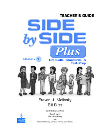
COMPUTER ASSISTED PART PROGRAMMINGComputer Assisted Part Programming was relatively simple, it was a suitable application formanual programming. Most parts machined on NC systems are considerably more complex. Inthe more complicated point-to-point jobs and in contouring applications, manual partprogramming becomes an extremely tedious task and subject to error. In these instances it ismuch more appropriate to employ the high-speed digital computer to assist in the partprogramming process. Many part programming language systems have been developed toautomatically perform most of the calculations which the programmer would otherwise be forcedto do. This saves time and results in a more accurate and more efficient part program.The part programmer’s jobThe difference in the part programmer’s job between manual programming and computerassisted programming is this. With manual programming, a manuscript is used which isformatted so that the NC tape can be typed directly from it. With computer-assisted partprogramming, the machining instructions are written in English-like statements of the NCprogramming language, which are then processed by the computer to prepare the tape. Thecomputer automatically punches the tape in the proper tape format for the particular NCmachine.When utilizing one of the NC programming languages, part programming can be summarized asconsisting basically of two tasks :1. Defining the geometry of the work part2. Specifying the tool path and/or operation sequenceLet us now consider these two tasks in computer-assisted part programming. Our frame ofreference will be for a contouring application, but the concepts apply for a positioningapplication as well.Fig: 1 Basic Geomentry Element
WORK PART GEOMETRY DEFINITION:No matter how complicated the work part may appear, it is composed of basic geometricelements. Using a relatively simple work part to illustrate, consider the component shown inFigure 1. Although somewhat irregular in overall appearance, the outline of the part consists ofintersecting straight lines and a partial circle. The holes in the part can be expressed in terms ofthe center location and radius of the hole. Nearly any component that can be conceived by adesigner can be described by points, straight lines, planes, circles, cylinders, and othermathematically defined surfaces. It is the part programmer’s task to enumerate the componentelements out of which the work part is formed. Each geometric element must be identified andthe dimensions and location of the element explicitly defined. Using the APT programminglanguage as an example, the following statement might be used to define a point :P1 – POINT/6.0, 1.125,0The point is identified by the symbol P1 and is located at x 6.0, y 1.125, and z 0.Similarly, a circle in the x–y plane might be defined by the APT statementC1 CIRCLE/CENTER, P1 , RADIUS, 1.12The center of circle C1 is Pi (previously defined) and the radius is 1.125.The various geometric elements in the drawing of Figure 9.7 would be identified in a similarfashion by the part programmer.TOOL PATH CONSTRUCTIONAfter defining the work part geometry, the programmer must next construct the path that thecutter will follow to machine the part. This tool path specification involves a detailed step-bystep sequence of cutter moves. The moves are made along the geometry elements which havepreviously been defined. To illustrate, using Figure 1 and the APT language, the followingstatement could be used to command the tool to make a left turn from line L2 onto line L3 :GOLFT/L3, PAST, L1This assumes the tool was previously located at the intersection of lines L2 and L3 and had justfinished a cut along L2. The statement directs the tool to cut along L3 until it just passes line L1.By using statements similar to the above, the tool can be directed to machine along the work partsurfaces, to go to point locations, to drill holes at those point locations, and so on. In addition togeometry definition and tool path specification, the part programmer also provides othercommands to the NC system. However, let us await Section 9.5, where we will consider a widerange of possible APT statements.
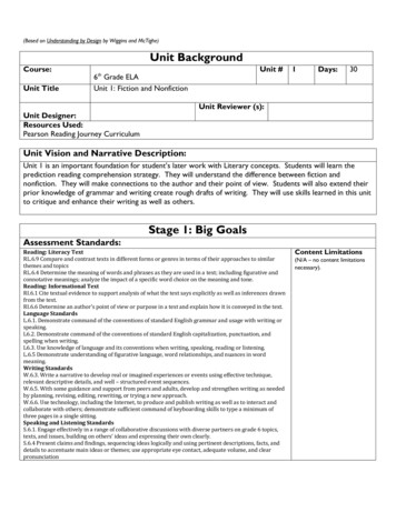
The computer’s jobThe computer’s job in computer-assisted part programming consists of the following steps:1. Input translation2. Arithmetic calculations3. Cutter offset computation4. Post processorThe sequence of these steps and their relationships to the part programmer and the machine toolare illustrated in Figure 2Fig.2 Steps in Computer Assisted Part ProgrammingINPUT TRANSLATION: The part programmer enters the program using the APT or otherlanguage. The input translation component converts the coded instructions contained in theprogram into computer-usable form, preparatory to further processing.ARITHMETIC CALCULATIONS: The arithmetic calculations unit of the system consists ofa comprehensive set of subroutines for solving the mathematics required to generate the partsurface. These subroutines are called by the various part programming language statements. Thearithmetic unit is really the fundamental element in the part programming package. This unitfrees the programmer from the time-consuming geometry and trigonometry calculations toconcentrate on the work part processing.CUTTER OFFSET COMPUTATION: When we described the second task of the partprogrammer as that of constructing the tool path, we ignored one basic factor the size of thecutting tool. The actual tool path is different from the part outline. I is is because the tool path isthe path taken by the center of the cutter. It is at the periphery of the cutter that machining takesplace.
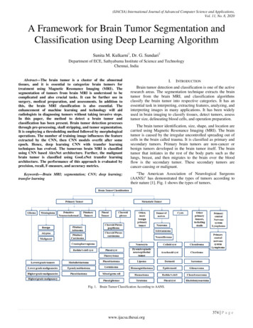
The purpose of the cutter offset computation is to offset the tool path from the desired partsurface by the radius of the cutter. This means that the part programmer can define the exact partoutline in his geometry statements. Thanks to the cutter offset calculation provided by theprogramming system, he need not concern himself with this task. The cutter offset problem isillustrated in Figure 3POST PROCESSOR. As we have noted previously, NC machine tool systems are different.They have different features and capabilities. They use different NC tape formats. Nearly all ofthe part programming languages, including APT, are designed to be general-purpose languages,not limited to one or two machine tool types. Therefore, the final task of the computer incomputer-assisted part programming is to take the general instructions and make them specific toa particular machine tool system. The unit that performs this task is called a post processor.The post processor is really a separate computer program that has been written to prepare thepunched tape for a specific machine tool. The input to the post processor is the output from theother three components: a series of cutter locations and other instructions. This is referred to asthe CLFILE or CLDATA (CL stands for cutter location). The output of the post processor is theNC tape written in the correct format for the machine on which it is to be used.Fig.3 Cutter Offset Problem in computer-assisted part programmingStructure of Part ProgramA part program is simply an NC program used to manufacture a part. Part programming for NCmaybe performed manually (manual part programming) or by the aid of a computer (Computeraided partprogramming).Many programming languages have been developed for part programming. The first that usedEnglishlikestatements and one of the most popular languages is called APT (for Automatically
ProgrammedTools). Many variations of APT have been developed, including ADAPT(ADaptation of APT), EXAPT(a European flavor of APT), UNIAPT (APT controller for smallercomputer systems), etc.NC programming for complex parts are generated using advanced computer programs(CAD/CAMprograms), which create automatically the machine code (so called G-code) in agraphic environment.Machine code is also largely used for manual part programming of simpleshapes and is covered inthe present section.Machine codeThe structure of a NC program written in machine code is standardized and for a two-axis NCsystemhas the following format:NC program block consists of a number of program words. The NC program is executed blockby block:each next block is entered in the system and executed only after entirely completing thecurrent block.Each program word is an ordered set of characteristics, letters and numbers, to specify a singleaction ofthe machine tool. Program words fall into two categories,Πmodal, which are active in the block in which they are specified and remain active in thesubsequent blocks until another program word overrides them; non-modal, which are only active in the block in which they are specified.Some of the most important program words are as follows sequence numbers (N****)Sequence numbers are a means of identifying program blocks. In some systems theyare not required although sequence numbers are needed in most canned cycles (coveredlater in this section); preparatory functions (also G-codes) (G**)Preparatory functions are used to set up the mode in which the rest of the operationis to be executed.Some of examples of G-codes are given in the table:G00 Positioning (not cutting)G01 Linear interpolationG02 Clockwise circular interpolationG03 Counterclockwise circular interpolationG20 Inch data inputG21 Metric data inputG54 Workpart coordinate presetG80 Canned cycle cancelG81-89 Canned cycles
G90 Absolute programmingG91 Incremental programming Dimension words (D****.***), where D stands for X, Z, U, or WDimension wordsspecify the coordinate positions of the programmed path. X andZ specify the absolutecoordinates, and U and W specify the incremental coordinates(absolute and incrementalprogramming are explained later in this section);Arc center coordinates (D****.***), where D stands for I, or KArc center coordinatesspecify the incremental coordinate position of the arc center (I inthe direction of X-axis,and K in the direction of Z-axis), measured from the arc startingpoint; Feed function (F**.**)Specifies the velocity of feed motion; Spindle control function (S****)Specifies spindle rotational speed in revolutions per minute, or cutting velocity in meterperminute depending on the type of NC system and machine tool; Tool calls (F**.**)The tool call word is used to access the required tool. It also gives the information for theradialcompensation of tool corner wear for each new run of the program (and eachnew part); Miscellaneous functions (M**)The M-function performs miscellaneous machine actions such as these listed in thetable:M00 Program stopM02 Program endM03 Start spindle CWM04 Start spindle CCWM05 Stop spindleM06 Execute tool changeM07 Turn coolant onM25 Open chuckM26 Close chuckProgram pointsThe NC system must know where the part is positioned in the work space. The procedure fordefining the work coordinate system (WPC) is called work piece coordinate setting. Twoimportant factors deal with work piece coordinate setting,Œwhere the part datum (the origin of the WPC) is situated with respect to the workpiece; Where the part datum is situated with respect to the machine tool. The WPC origin may be located at any part of the work piece, but to avoid dimensionalrecalculations and respectively errors, the good programmers will chose the WPC origin at thepoint, from where the part features are dimensioned:
Fig:4 Selection of Work Piece Coordinate originThe methods for locating the positions of the WPC origin with respect to the machine toolvaries for each machine tool. Some systems use a zero-set button to set the WPC origin. Onother types of NC systems, the WPC is set with a G54 or a G92 code followed by X, and Zdimensions.The G54 code tells the machine where the position of the WPC measured from themachine zero point is. Machine zero point (machine datum) is a fixed point on themachine tool and cannot be programmed or altered.Fig:5 Setting of WPCAnother important point is the program start point (also tool home position). This point isselected by the programmer at some distance from the work piece, not too far to save sometime when the tool returns home, and not too close to allow for safe indexing of the toolturret when the cutting tool is changed. The program, therefore the new part machining,starts and ends with the tool at home position, but the tool needs also to be returned to homewhenever a tool change take place during the program execution.
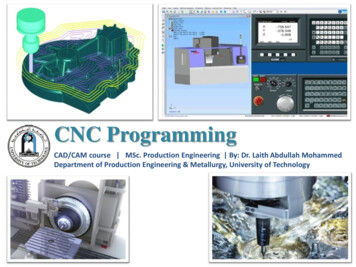
Linear and circular interpolationA G01 linear interpolation code moves the tool to a position with coordinates defined withprogram words in a straight, including angular line at the specified with F-code feed rate. Thecommand is modal and is active until either a G00, or G02, or G03 overrides it.NC system are capable of commanding a circular motion. Arc movement is known as circularinterpola-tion and is carried out with a G02 (clockwise circular interpolation) or G03 (counterclockwise circular interpolation) codes. The arc radius is specified either by the incrementaldimensional words I and K, which defines the position of arc centerpoint with respect to the arcstart point, or directly by the radius R-code. In both methods, the program block, which startswith a G02 or G03 codes must also include the coordinates of the arc end point. If R-code isused, arcs less than 180o are given a positive radius and arcs more than 180 o are given a negativeradius value:Fig:6 Linear and circular interpolation.TOOL LENGTH COMPENSATIONTool length compensation is instated with a G43 word. Included within the G43 command is anH-word that specifies the offset number in which the tool length compensation value is stored.You must also include a Z-word in the G43 command, telling the machine where you want thetool tip to be positioned.Cutting tools used on machining centers differ from one another. For one thing, there are avariety of cutting tool types that are used on machining centers, including center drills, spotdrills, drills, taps, reamers, boring bars, end mills, and face mills (among many others). Each typeof tool requires a different way of gripping the actual cutting tool in its holder. Some tools (like
some straight shank tools) use a collet system. Others (like end mills) use a set- screw to hold thecutting tool in place. Yet others (like face mills and taps) require a very special style of toolHolder–designed especially for the cutting tool.Fig:7 Tool Length compensationTool length compensation will allow you to write programs even though you don’t know howlong the cutting tools will be at production time.Tool’s Length Will Vary from Each Time it is AssembledWhen a cutting tool is assembled more than once (even with the same components), its lengthwill usually vary. Consider, for examples, straight shank tools that are placed in collet holders.Each time you assemble the tool, it will be of a different length. Tool length compensation willallow you to use the same program over and over again, even though each tool’s length changesfrom one time the job is run to the next.Tool Data is Entered Separately from the ProgramThe same program will work regardless of how long each cutting tool is. The program tellsthe control where to look for the length of each tool. During setup, the setup person (orsomeone) assembles and measures each cutting tool. The length of each tool is then placed inthe appropriate location (a tool offset register).Sizing and Trial Machining Must Often be DoneThe importance of being able to trial machine in order to machine the first work piececorrectly. And during a given tool’s life a tool will wear and cause the surface beingmachined to change. Tool length compensation allows the setup person and operator toeasily hold size for Z-axis related dimensions (pocket depths, hole-depths, etc.). The programneed not be changed when work piece dimensions must be adjusted.
CUTTER RADIUS COMPENSATIONCutter Radius Compensation also known as CRC, is a function of the CNC controller toautomatically shift the tool from the cutter center line to the cutter edge along the programmedcutter path. If it were not for CRC the cutter path locations would have to be calculated to thecutter center line. Cutter Radius Compensation (CRC) can be used to program continuous pathmilling operations.There are a few special rules that must be applied to the programming method when using CRC.1) The point before the CRC approach and exit from the contour cut must be equal to orgreater than the cutter radius.2) CRC can only be started and stopped along linear motion.3) CRC can only be applied to 2 axis of motion at a time.4) The use of more than one non motion block in a row is not allowed.Three main advantages to using Cutter Radius Compensation (CRC) programming1)The programmer can use point values that are directly along the cutter path rather than havingto calculate the tool center.2)During production runs, cutters of different sizes can be used such as undersize tools when theoriginal size tool is no longer available. It is a simple radius offset value change in the machinecontrol to achieve this. The programming will remain the same.3)A program section or operation can be used over and over with different tools to createroughing passes and finish passes. This is done by changing the radius offset value and usingmultiple offsets.TOOL NOSE RADIUS COMPENSATIONDuring processing of the work piece contour, due to the tool radius, tip and a half Diameter ofthe existence of the tool tip and work piece center or imaginary contours donot coincide. If the digital system does not have automatic tool radius compensationfunction can only be converted into contour programming tool center path, and thenprocessed. When the tool wear, heavy wear, tool change, to re-calculate the tool centerpath, modify the program. However, when the numerical control system with automatic toolradius compensation function, you can just press the work piece contour programming,CNC system will automatically calculate the tool center path, deviate from the contour ofthe tool with a radius value, even if the tool wear, heavy wear, tool change, also need tomodify the radius of the tool deviate from the contour value that offsets, tool radius
am.CNC lathe programming is based on imaginary tip movement; the actual tip location is asmall circular, conical surface and in the turning arc will produce processing errors. If the use ofnose radius compensation, pre-tip to tip radius and arc parameters such as input to the toolposition within the database, according to work piece contour programming, numerical controlsystem automatically calculates the tool center trajectory, the control center path for cuttingknives processing, eliminating the tip of the arc caused by processing errors. You can alsomodify the value to eliminate abrasion tool wear or tool failure caused by processing errors.Similarly, in CNC milling, the tool radius offset pre-register in the specified register, theuse of the tool radius compensation commands, by adjusting the tool radius compensation valueto compensate for tool wear, in order to eliminate the tool wear caused by processing errors . Atthe same time even if a replacement tool or tool re-grinding, as long as the contour is the same,processing the same coordinate system, you can use the original program. At the same time asthe application can also adjust the tool radius compensation amount to the same profile using thesame procedures under the same conditions, rough and finish.CyclesThe repetitive program (and machining) sequence is called a cycle. Cycles are classified into twoprinciplegroups,Πcanned cycles (also fixed cycles), and user-defined cycles (sub-routines).Canned cycles are an inbuilt feature of the NC system. The usage of canned cycles makes easierprogrammingfor threading, drilling holes and other repetitive machining tasks. The next figureillustrates athread cutting canned cycle:Fig:7 Threaded canned cycle
User sub-routines are useful, when the necessary canned cycle is not available. The user subroutine is a NC program, which describes a sequence of operations, which is often repeatedwhen machining particular part. The sub-routine is called from the main NC program with aM98 command.A special type of user-defined cycles is so-called macros, which are generic cycles withparametric variables. The macro is called from the main program with a set of numerical valuesfor these variables. This allow to use one and the same macro to machine different in size, butsimilar in shape components. Programming with macros is often referred to as a parametricprogramming.Mirror ImageThe mirroring command is used when features of components shares symmetry about one ormore axes and are also dimensionally identical. By using this code components can be machinedusing a single set of data and length of programs can be reduced.G10 cancellation of mirroring imageG11 Mirror image on X axisG12 Mirror image on Y axisG13 Mirror image on Z axisFig. 8 Illustrative Example for mirroring
Parametric ProgrammingParametric programming can be compared to any computer programming language like BASIC,C Language, and PASCAL. However, this programming language resides right in the CNCcontrol and can be accessed at G code level, meaning you can combine manual programmingtechniques with parametric programming techniques. Computer-related features like variables,arithmetic, logic statements, and looping are available. Like computer programming languages,parametric programming comes in several versions. The most popular is Custom Macro B (usedby Fanuc and Fanuc-compatible controls). Others include User Task (from Okuma), Q Routine(from Sodick), and Advanced Programming Language [APL] (from G& L)In addition to having many computer-related features, most versions of parametric programminghave extensive CNC-related features. Custom macro, for example, allows the CNC user to accessmany things about the CNC control (tool offsets, axis position, alarms, generate G codes, andprogram protection) right from within a CNC program. These things are impossible with onlynormal G code programming techniques.Applications:Many companies have excellent applications for custom macro and don't even know it. Ofcourse, if you don't even know you have an application for something, it's impossible to evenconsider using it. While these applications are covered in much greater detail during our videocourse and CD-rom course, applications for custom macro fall into five basic categories.Example:To stress what can be done with parametric programming, we show a simple example written incustom macro B for a machining center application. It will machine a mill a hole of any size atany location. Notice how similar this program is to a program written in BASIC.
ProgramO0001 (Program number)#100 1. (Diameter of end mill)#101 3.0 (X position of hole)#102 1.5 (Y position of hole)#103 .5 (Depth of counter bored hole)#104 400 (Speed in RPM)#105 3.5 (Feed rate in IPM)#106 3. (Tool length offset number)#107 2.0 (Diameter of counter bored hole)G90 G54 S#104 M03 (Select abs mode, coordinate system, start spindle)G00 X#101 Y#102 (Rapid to hole center)G43 H#106 Z.1 (Instate tool length compensation, rapid to approach Z position)G01 Z-#103 F[#105 / 2]Y[#102 #107 / 2 - #100 / 2] F#105G02 J-[#107 / 2 - #100 / 2]G01 Y#102G00 Z.1M30Automatically Programmed Tool (APT)The API language was the product of the MIT developmental work on NC programmingsystems. Its development began in June 1956, and it was first used in production around 1959.Today it is the most widely used language in the United States. Although first intended as acontouring language, modern versions of APT can be used for both positioning and continuouspath programming and continuous-path programming in up to five axes.AUTOSPOT (AUTOMATIC SYSTEM FOR POSITIONNING TOOLS). This was developedby IBM and first introduced in 1962 for PTP programming. Today’s version of AUTOSPOT canbe used for contouring as well.SPLIT (SUNDSTRAND PROCESSING LANGUAGE INTERNALLY TRANSLATED). Thisis a proprietary system intended for Sundstrand’s machine tools. It can handle up to five axispositioning and possesses contouring capability as well. One of the unusual features of SPLIT isthat the post processor is built into the program. Each machine tool uses its own SPLIT package,thus obviating the need for a special post processor.COMPACT II. This is a package available from Manufacturing Data Systems, Inc. (MDSI), afirm based in Ann Arbor, Michigan. The NC language is similar to SPLIT in many of itsfeatures. MDSI leases the COMPACT II system to its users on a time-sharing basis. The partprogrammer uses a remote terminal to feed the program into one of the MDSI computers, whichin tum produces the NC tape.
ADAPT (ADAPTATION OF APT). Several part programming languages are based directly onthe APT program One of these is ADAPT, which was developed by IBM under Air Forcecontract. It was intended to prov
When utilizing one of the NC programming languages, part programming can be summarized as consisting basically of two tasks : 1. Defining the geometry of the work part 2. Specifying the tool path and/or operation sequence Let us now consider these two tasks in computer-assisted part programming.