Transcription
MAXREFDES103# Health Sensor BandUser GuideUG7145; Rev 0; 1/20AbstractThis user guide provides information about preparing and running the MAXREFDES103# healthsensor band. This platform uses a high-sensitivity PPG biosensor, power-management IC(PMIC), and microcontrollers from Maxim Integrated in a wrist-worn design that allows thecapture of biometric signals important to healthcare. The platform also contains algorithms forcalculating heart health based on the biosensor measurements.Maxim IntegratedPage 1 of 42
Table of ContentsDetailed Hardware Description . 5Required Equipment . 5System Diagram . 7Operating the Health Sensor Band . 8Power On/Off. 8Button Functionality . 9Color Definitions for LED Status . 9How to Position the Device on the Wrist . 10Software Updates . 11Installing the PC GUI . 11Updating the Micro Board Firmware (.bin) on the MAXREFDES103# . 12Updating the MAX32664 Sensor Hub Algorithm Firmware (.msbl) . 13Evaluation GUIs . 17Using the DeviceStudio PC GUI . 17Installing the Windows 7 Driver for the PC GUI . 17USB Connection . 19Bluetooth LE Connection for Windows 10 . 22Starting the PPG Measurement . 24Data Format of the Log File . 26Flash Logging of Data . 27Downloading the Log File . 27Maxim Health Sensor Platform App for Android . 30Installing the App . 30Optical Heart-Rate Monitoring . 31Pulse Oximetry . 33Heart-Rate Variability. 36Respiration Rate . 38Notes on the Enclosure. 40Time-Alignment Method for Comparing PPG Data to ECG Data . 40SpO2 Calibration. 41Revision History . 42Maxim IntegratedPage 2 of 42
List of FiguresFigure 1. MAXREFDES103# wearable form factor in detail. . 5Figure 2. MAXREFDES103# system diagram. . 7Figure 3. USB Type-C cable (left) and MAXDAP Pico Adapter board (right). . 8Figure 4. PPG measurement. . 10Figure 5. Install the .msi file. . 11Figure 6. MAXDAP Pico Adapter .bin firmware updates port connected to the PC. . 12Figure 7. DAPLINK drive on the PC. . 12Figure 8. Reset button on the MAXDAP-TYPE-C Pico Adapter board. . 13Figure 9. MAXDAP Pico Adapter board device port connected to the PC. . 13Figure 10. Maxim DeviceStudio scan options. . 14Figure 11. Maxim DeviceStudio connected devices. . 14Figure 12. Device tab to update the MAX32664 .msbl. . 15Figure 13. Warning message. . 15Figure 14. Upload the embedded heart-rate algorithm to the MAX32664. . 16Figure 15. .msbl file flashed successfully. . 16Figure 16. CDC DEVICE in Device Manager. . 17Figure 17. Locate and install the driver manually. . 18Figure 18. Browse to the extracted release package. . 18Figure 19. Select Install this driver software anyway. . 19Figure 20. Mbed Serial Port in Device Manager. . 19Figure 21. USB connection to PC using a USB Type-C cable (left) and MAXDAP Pico Adapterboard device port (right). . 19Figure 22. Scan for available devices. . 20Figure 23. Successful connection over USB. . 21Figure 24. Scan for available Windows BLE devices. . 22Figure 25. Bluetooth LE device selection. . 23Figure 26. Successful connection over Bluetooth LE. . 24Figure 27. Configure for Algorithm mode. . 25Figure 28. Measurement data displayed. . 25Maxim IntegratedPage 3 of 42
Figure 29. Example log file PPG .csv. . 27Figure 30. Power button on the MAXREFDES103#. . 28Figure 31. MSD connection to PC using USB Type-C cable. . 28Figure 32. Flash Log Parser. . 29Figure 33. Install the .apk. 30Figure 34. Run the .apk. . 30Figure 35. Grant permissions and allow access. . 30Figure 36. Click on the device named HSPSP02 . . 31Figure 37. Main menu of the Maxim Health Sensor Platform app. . 31Figure 38. Start heart-rate measurement. . 32Figure 39. Heart-rate measurement. . 32Figure 40. Positioning the health sensor band. . 33Figure 41. Start SpO2 measurement. . 33Figure 42. IR and Red signals displayed during SpO2 measurement. . 34Figure 43. SpO2 measurement. . 34Figure 44. Motion has turned red to indicate excessive motion. . 35Figure 45. Stop monitoring icon. . 35Figure 46. Retrieving the .csv log file from the Android device. . 36Figure 47. Start heart-rate variability measurement. . 37Figure 48. Heart-rate variability measurement. . 37Figure 49. Start the respiration rate measurement. . 38Figure 50. Respiration rate measurement. . 38Figure 51. Sleep quality assessment. . 39Figure 52. PPG and ECG data sets that have been time-aligned. . 40List of TablesTable 1. Button Functionality . 9Table 2. Color Definitions for LED Status . 9Table 3. Data Table Column Definitions for the Log File (PPG *.csv) . 26Maxim IntegratedPage 4 of 42
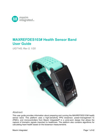
Detailed Hardware DescriptionLeftTop ViewRightMAC Address(Last Four Digits)USB Type-CSerial NumberButton FPower ButtonStatus LEDBottom ViewPhotodiodesLEDsFigure 1. MAXREFDES103# wearable form factor in detail.Required EquipmentThe MAXREFDES103# platform includes the following components: Micro board MAX32630 microcontroller MAX20303 power-management IC (PMIC) Dual-mode Bluetooth connection Tri-color status LEDSensor board MAX86141 analog front-end and optical heart rate sensor with one green LEDs, onered LED, one IR LED, and two photodiodesThe Bluetooth word mark and logos are registered trademarks owned by Bluetooth SIG, Inc. and any use of such marksby Maxim is under license.Maxim IntegratedPage 5 of 42
MAX32664 microcontroller with embedded heart-rate algorithm Three-axis accelerometer MAX4740 quad SPDT switch which, in combination with the MAX86140/41, enablesdifferent LED and PD configurations One green LED, two combination RGB LEDs (One of these RGB LEDs is currently notused by the algorithm. The extra LED is reserved for future use: To simplify the design,the extra LED and the MAX4740 may be removed for the heart rate, SpO2 use case.) MAXDAP Pico Adapter board to be used during a firmware upgrade for the micro board Health sensor band enclosureTwo USB Micro-B cables for firmware upgrade of the micro board or for PC communicationwith the micro board or charging of the health sensor bandBatteryOne USB Type-C cable for PC communication with the micro board (Windows 7 orWindows 10) or charging of the health sensor bandAdditional requirements: PC (Windows 10 only) with Bluetooth connection for data streaming and loggingAndroid device with Bluetooth connection for data streaming and loggingAndroid is a registered trademark of Google Inc.USB Type-C is a trademark of Universal Serial Bus Implementers Forum, Inc.Windows is a registered trademark of Microsoft Corporation.Maxim IntegratedPage 6 of 42
System DiagramMICROCONTROLLER BOARDSENSOR BOARDSENSOR HUBMAX20303POWER-MANAGEMENT rm Cortex M4F MCUBOOTLOADERM4F MCUMX25U51245GZ4I5464MB FLASH MEMORYBMI160HOST ACCELEROMETERHR ALGORITHMArm Cortex SPI1QSPIMAX86141I2COPTICAL SENSORGPIO1USB-C CONNECTORLED1DRVLED2DRVKX1223-AXIS ACCEL(OPTIONAL)LED3DRVMAX4740QUAD SPDT SWITCHLED4 LED1 LED5 LED2 LED6 LED3Figure 2. MAXREFDES103# system diagram.Arm and Cortex are registered trademarks of Arm Limited.Maxim IntegratedPage 7 of 42
Operating the Health Sensor BandPower On/OffThe MAXREDES103# can be powered on by pressing and holding the power button for at leastone second.Alternatively, the device powers on when connected to a PC using a USB Type-C cable or whenconnected to a MAXDAP Pico Adapter board.binFirmwareUpdatesFigure 3. USB Type-C cable (left) and MAXDAP Pico Adapter board (right).The MAXDAP Pico Adapter board has two USB Micro-B connectors. The bottom connector nextto the pushbutton is used for updating the .bin firmware of the micro board. The right connectornext to the “Device” label is used for the serial connection between the MAXREFDES103# andthe PC. Both connectors provide power to the MAXREFDES103#.To power off, press and hold the power button on the MAXREFDES103 for at least 12 seconds.Note: If the device becomes unresponsive, a hard reset to the device may be performed by usingthe power-off and power-on procedures.Maxim IntegratedPage 8 of 42
Button FunctionalityTable 1 describes the functionality of the two buttons.Table 1. Button FunctionalityExtra LongPress (12s)ButtonShort PressLong Press (3s)Power ButtonTurn off/on status LED; topower on, press for 1sPower off (after a 3s press, LEDblinks magenta and if the button isreleased while blinking magenta,the device is powered off)Power offButton FStart/stop data collection(flash logging)N/AN/AColor Definitions for LED StatusTable 2 describes the state of the device for a given color and blinking status.Table 2. Color Definitions for LED StatusLED ColorSolid (No Blinking)Fast BlinkSlow BlinkRedFailure detected – needssystem resetCommunications withMAX32664Battery critically low( 10%)GreenUSB connectedStreaming USB dataDevice is readyBlueBluetooth Low Energy(Bluetooth LE, or casuallyknown as BLE) connectedStreaming Bluetooth LE dataReservedMagentaReservedFast blinks for 2s after a powerbutton long press. If the buttonis released while fast blinking,then the device is powered offReservedCyanReservedFlash logging active5 blinks indicate thatflash logging is completeYellowSystem is initializingMAX32664 programming isactiveBattery low (10% to25%)WhiteMSD modeReservedReservedOffLEDs have been turned offN/AN/AMaxim IntegratedPage 9 of 42
How to Position the Device on the WristPosition the health sensor band approximately one finger width up the arm from the wrist bone. Ifpossible, wear the health sensor band on the non-dominant hand, as this improves the quality ofthe data. The health sensor band should fit tightly but comfortably around the wrist. Make surethe skin has direct contact with the openings for the LED/photodiodes at the center of the back ofthe health sensor band.Figure 4. PPG measurement.Maxim IntegratedPage 10 of 42
Software UpdatesThe MAXREFDES103# has been pre-loaded with the firmware that was available duringproduction. A firmware upgrade is strongly recommended to ensure that the most recent set offirmware is loaded. To update the firmware, perform the following steps in this exact order:1. Install the PC GUI using the .msi file2. Flash the micro board .bin file3. Flash the algorithm .msbl fileInstalling the PC GUI1. Uninstall any previously installed versions of the DeviceStudio GUI.2. Download and extract the Eval Package for either Windows 10 (supports USB andBluetooth) or Windows 7 (supports only USB) from the Maxim website for theMAXREFDES103#.Note: The software package includes the latest firmware .bin, algorithm .msbl, and thecorresponding Windows application .msi. All three must be updated to ensurecompatibility.3. Double click on the .msi file. Check the box for “I accept the terms in the LicenseAgreement.” Click Install, and then click Finish.Figure 5. Install the .msi file.Maxim is a registered trademark of Maxim Integrated Products, Inc.Maxim IntegratedPage 11 of 42
Updating the Micro Board Firmware (.bin) on the MAXREFDES103#Firmware upgrades to the MAX32630 may be performed using the provided MAXDAP PicoAdapter board per the following steps.Note: The software package includes the latest .bin firmware, .msbl algorithm, and thecorresponding .msi Windows application. All three components must be updated to ensurecompatibility.1. Connect the MAXDAP Pico Adapter board .bin firmware updates port to the PC using theUSB Micro-B cable.binFirmwareUpdatesFigure 6. MAXDAP Pico Adapter .bin firmware updates port connected to the PC.2. Wait for the Windows drivers to install. After the drivers have installed, the PC recognizesthe device, which shows up as a drive named DAPLINK on the PC.Figure 7. DAPLINK drive on the PC.3. To flash the host firmware to the MAX32630, drag and drop the .bin binary file into theDAPLINK drive on your PC.4. The MAXREFDES103# does not automatically reset after flashing the micro board withthe new firmware. Press and release the reset button on the MAXDAP Pico Adapter boardto restart the health band. The button is located below the top USB Micro-B connector.Maxim IntegratedPage 12 of 42
ResetFigure 8. Reset button on the MAXDAP-TYPE-C Pico Adapter board.Updating the MAX32664 Sensor Hub Algorithm Firmware (.msbl)After the host firmware binary is updated to the micro board, the .msbl Biometric Sensor Hubalgorithm must be updated with the PC GUI by performing the following steps.Note: The software package includes the latest .bin firmware, .msbl algorithm, and thecorresponding .msi Windows application. All three components must be updated to ensurecompatibility.1. Open the Maxim DeviceStudio Windows application.2. Connect the MAXDAP Pico Adapter board device port to the PC using the USB Micro-Bcable. Wait five seconds.DeviceFigure 9. MAXDAP Pico Adapter board device port connected to the PC.3. Select the Serial over USB/Bluetooth scan option, then click Scan.Maxim IntegratedPage 13 of 42
Figure 10. Maxim DeviceStudio scan options.4. Verify that the Devices list in the Connected Devices section shows PPG.Figure 11. Maxim DeviceStudio connected devices.Maxim IntegratedPage 14 of 42
5. Go to the Device tab and select Update SmartSensor MAX32664 Software. Thenselect Update Firmware and select the *.msbl file from the extracted Eval Package andclick Open.Figure 12. Device tab to update the MAX32664 .msbl.6. Click OK on the Warning! pop-up window.Figure 13. Warning message.The embedded algorithm for heart-rate and SpO2 measurement is uploaded to theMAX32664 microcontroller on the sensor board.Maxim IntegratedPage 15 of 42
Figure 14. Upload the embedded heart-rate algorithm to the MAX32664.Figure 15. .msbl file flashed successfully.Maxim IntegratedPage 16 of 42
Evaluation GUIsThe MAXREFDES103 is compatible with two evaluation GUIs: the DeviceStudio PC GUI and theMaxim Health Sensor Platform GUI App for Android.The DeviceStudio PC GUI provides the ability to configure the algorithm, as well as to view andlog the processed/raw data. In raw data mode, the algorithm is disabled and the AFE settingsmay be configured. In algorithm mode, the embedded Maxim-supplied algorithm is configuredand processed, and raw data for heart rate and SpO2 are displayed. DeviceStudio also has aparser utility that converts the logged data in flash memory to .csv format.The Maxim Health Sensor Platform GUI allows the display of processed data and the logging ofdata through an Android app. The app displays the processed data from the embedded algorithmfor: Heart RateSpO2In addition to displaying the data from the embedded algorithm, the app includes additionalalgorithms: Heart Rate VariabilityRespiration RateSleep QualityUsing the DeviceStudio PC GUIThe Windows 10 PC GUI currently supports connection to the MAXREFDES103# through USBor Bluetooth LE. The Windows 7 PC GUI only supports connection to the MAXREFDES103#through USB.Installing the Windows 7 Driver for the PC GUITo use the PC GUI on a Windows 7 PC, installing the driver manually might be required. Tomanually install the USB serial driver, perform the following steps:1. Uninstall any previously installed versions of the DeviceStudio GUI.2. Download the Windows 7 Eval Package from the Maxim website for theMAXREFDES103#.3. Extract the .zip file to a known location.4. Open Device Manager, which can be found in the Windows Control Panel.5. If manual driver installation is needed, the MAXREFDES103# appears under Otherdevices as CDC DEVICE. Right-click CDC DEVICE and select Properties.Figure 16. CDC DEVICE in Device Manager.6. If Update Driver is grayed out, click Change Settings, and then click Update Driver Maxim IntegratedPage 17 of 42
7. Select Browse my computer for driver software.Figure 17. Locate and install the driver manually.8. Navigate to the location of the.zip file that was extracted in step 3, then click Next.Figure 18. Browse to the extracted release package.Maxim IntegratedPage 18 of 42
9. When prompted by the Windows Security window, click Install this driver softwareanyway.Figure 19. Select Install this driver software anyway.10. After the driver is installed successfully, the MAXREFDES103# appears as an Mbed Serial Port. (The COM port number used may be different from COM4.)Figure 20. Mbed Serial Port in Device Manager.USB Connection1. Connect the health sensor band to the PC with a USB Type-C cable (or with the MAXDAPPico Adapter board using a USB Micro-B cable).Figure 21. USB connection to PC using a USB Type-C cable (left) and MAXDAP PicoAdapter board device port (right).Mbed is a registered trademark of Arm Limited.Maxim IntegratedPage 19 of 42
2. Under Scan Mode, select Serial over USB/Bluetooth, then click Scan.Figure 22. Scan for available devices.Maxim IntegratedPage 20 of 42
3. Verify that the Devices list in the Connected Devices section shows PPG.Figure 23. Successful connection over USB.Maxim IntegratedPage 21 of 42
Bluetooth LE Connection for Windows 101. Under Scan Mode, select Windows BLE and click Scan.Figure 24. Scan for available Windows BLE devices.2. Select the health sensor device for pairing. (The highest signal strength in dBm will usuallybe the closest health sensor device, and each MAXREFDES103# is labeled with the lastfour digits of the MAC address). Click Connect.Maxim IntegratedPage 22 of 42
Figure 25. Bluetooth LE device selection.Maxim IntegratedPage 23 of 42
3. Verify that the Devices list under Connected Devices shows PPG.Figure 26. Successful connection over Bluetooth LE.Starting the PPG Measurement1. Click Launch Tool.2. Select Algorithm to allow the MAX32664 algorithm to dynamically adjust the AFE settingsand measure the heart rate and SpO2.3. Select 0:Continuous HRM and SpO2 to configure the algorithm to run continuously.4. Select SCD to enable skin contact detection.5. Select AEC to enable automatic exposure control.6. Click Default to configure the AEC to the default settings.7. Select Accelerometer to plot the accelerometer data.8. Select Algorithm Data to see the algorithm data: HR (bpm), HR confidence (%), RR peakinterval (R-to-R msec), RR Confidence, Activity, SpO2 (%), SpO2 Confidence (%), RValue, SpO2 % Completion (for one-shot), Low Signal Flag, Motion Flag, SpO2 State, andSCD State.9. Select Log to File and Write Header to save the data to a file.10. Click Start Monitoring to show the measurement data.Maxim IntegratedPage 24 of 42
Figure 27. Configure for Algorithm mode.Figure 28. Measurement data displayed.Maxim IntegratedPage 25 of 42
Data Format of the Log FileTable 3. Data Table Column Definitions for the Log File (PPG *.csv)Log File HeadingsTimeSample CountGreen CountGreen2 CountIR CountRed CountX Axis Acceleration (g)Y Axis Acceleration (g)Z Axis Acceleration (g)Operating ModeHeart Rate (bpm)HR Confidence (%)RRRR Confidence (%)ActivityR ValueSPO2 Confidence (%)SPO2 (%)SPO2 Percent CompleteLow Signal QualityMotion FlagWSPO2 Low PiUnreliable RSPO2 StateSCD StateSAMPLE TimeMaxim IntegratedDescriptionTimestamp in minutes, seconds, and tenths of seconds (MM:SS.T)Data index ranging from 0 to 255 for monitoring if samples are droppedduring Bluetooth transmissionGreen counts detected by photodiode 1Green counts detected by photodiode 2IR countsRed countsAcceleration in x-axis, in unit of gAcceleration in y-axis, in unit of gAcceleration in z-axis, in unit of g0: Continuous HRM and continuous SpO21: Continuous HRM and one-shot SpO22: Continuous HRM3: One-shot HRM4: One-shot HRM and one-shot SpO25: Activity tracking6: SpO2 calibrationHeart rate, in unit of beats per minHeart-rate algorithm extraction confidence; a threshold confidence 85% isrecommendedR-to-R peak interbeat interval time (ms) of the QRS heart beat waveR-to-R confidence level, 0 to 100%0: Rest1: Other2: Walk3: Run4: Bike5: RhythmicSpO2 R value (R is defined in Maxim Application Note 6845)SpO2 confidence level; 0 to 100%SpO2 value; 0 to 100%SpO2 percent complete (only applicable for one-shot mode); 0 to 100%0: Good SpO2 signal quality1: Low SpO2 signal quality0: Little or no motion1: Excessive motion0: Normal Perfusion Index1: Low Perfusion Index0: Measurement of SpO2 R is reliable1: Measurement of SpO2 R is not reliable0: LED adjustment1: Computation2: Success3: TimeoutSkin contact state:0: No decision1: Off skin2: Contact with object3: On skinTimestamp in secondsPage 26 of 42
Figure 29. Example log file PPG .csv.Flash Logging of DataTo log PPG data to on-board flash memory, perform the following steps.To start flash logging from the PC GUI:1. Set up PPG measurement on the PC GUI as instructed in the Using the PC GUI sectionand ensure that the Log to Flash box is checked and the Log to File box is unchecked.2. Click Start Monitoring. Data is not streamed to the GUI or app while flash logging isenabled.3. At this point, you can disconnect the USB Type-C cable or Bluetooth LE connection to logdata while untethered.To start flash logging from the health band:1. Press and release Button F.To start flash logging from the Android app:1. Click on the three vertical dots near the top right and select the Log to Flash box.If the MAXREFDES103# is still tethered to the PC device, flash logging can be stopped bypressing the Stop button in the GUI or app. Alternatively, Button F may be pressed and releasedto stop flash logging.Downloading the Log FileAfter flash logging is complete, download and parse the log file using the following steps:1. Ensure that the USB Type-C cable is not connected, and power off the MAXREFDES103#by holding the power button down for 12 seconds.Maxim IntegratedPage 27 of 42
Power ButtonFigure 30. Power button on the MAXREFDES103#.After the MAXREFDES103# is powered down, hold Button F on the MAXREFDES103#and insert the USB Type-C cable (or the MAXDAP Pico Adapter board with a USBMicro-B cable, as pictured in Figure 31) into the USB Type-C connector of theMAXREFDES103#. Continue holding Button F until the status LED is slowly flashingwhite.USB-CButton FStatus LEDFigure 31. MSD connection to PC using USB Type-C cable.2. If done correctly, the MAXREFDES103# boots into mass storage device mode.3. The device appears in Windows Explorer as a USB drive, and you can copy-paste filesfrom the device.4. Copy the “.maximlog” file to your PC hard drive.Note: The log files are in raw binary format and need to be parsed to convert them to areadable .csv format.5. In the PC GUI, open the Flash Log Parser from the Tools menu.Maxim IntegratedPage 28 of 42
6. Select the .maximlog file, choose an output folder, and click PARSE. A .csv file isgenerated in the output folder containing the parsed log file.Figure 32. Flash Log Parser.Maxim IntegratedPage 29 of 42
Maxim Health Sensor Platform App for AndroidDownload the latest .bin, .msbl and .apk from the Maxim MAX32664 webpage. Flash theMAXREFDES103# with the latest .bin and .msbl as previously described.Installing the App1. After flashing the .bin, .msbl, and.apk, install and run the .apk on your Android device.Figure 33. Install the .apk.Figure 34. Run the .apk.2. Grant the permissions and device location access when the .apk is installed.Figure 35. Gran
Maxim Integrated Page 6 of 42 MAX32664 microcontroller with embedded heart-rate algorithm Three-axis accelerometer MAX4740 quad SPDT switch which in ,combination with the MAX8614140/, enables