Transcription
Software for Architecture,Engineering and ConstructionCYPE –Revitinteroperability guideUSER GUIDEV.2.0Developing projects with CYPE and REVIT
Contents1Introduction . 42IFC concepts . 52.1 IFC terminology and structure . 52.2 Features of a Revit IFC . 63Revit - CYPE Workflow. 73.1 General settings. 73.2 Open BIM plugin for Revit . 83.3 Analysis of possible export errors . 94General settings . 104.1 Mapping settings . 104.2 Levels . 124.3 Rooms . 134.4 Walls . 164.5 Floors . 184.6 Roofs . 194.7 Plumbing fixtures . 204.8 Links . 264.9 Central and local models; worksets . 2754.10Origin, base and survey points . 284.11Phases . 29Structures. 305.1 Structural analysis with CYPECAD . 306Installations . 316.1 Analysis of general installations . 316.2 Analysis of editable installations . 32
7Energy analysis . 337.1 Spaces . 337.2 Curtain walls . 347.3 North of the project . 367.4 Energy settings . 377.5 Foundation slabs and screed . 388Exporting from CYPE to Revit. 418.1 Tags . 418.2 Schedules . 428.3 Filter . 428.4 Convert to native . 439Bill of quantities . 4510 Augmented reality . 46
1IntroductionThis guide establishes guidelines for the optimum communication between thearchitectural modelling application REVIT, and CYPE’s specialist technical programs.This communication is based on the IFC format (acronym for INDUSTRY FOUNDATIONCLASSES). IFC is an open data exchange format in the architecture, engineering andconstruction sector. It is free to access (as it does not depend upon any particulardeveloper), and it allows for the exchange of model information between applications fromdifferent developers.It is not possible to develop efficient BIM models without taking into account the intendedBIM USES from the start. In this case, by not including the requirements of the IFC formatand of the CYPE tools as another BIM Use upon starting a new project with REVIT, it willlead to the appearance of interoperability problems that can end up halting the workflow.This is because there are two types of possible interaction with an IFC– viewing theinformation that it contains (e.g. with an IFC viewer) and working with this information(e.g. with CYPE’s analysis solutions). Whilst the first case is relatively easy to achieve, thesecond interaction is very sensitive due to differences in the internal information structuresof each software program.The IFC format is capable of transferring data from one application to another, but thisdoes not mean that this data follows the fundamental internal norms of the softwarewhich it is transferred to. For example, general purpose software like Revit or Archicad,allow the user to model elements in various ways. Such flexibility is possible because theydo not have to respond to complex specific calculations for detailed code justifications. Onthe other hand, in CYPE’s solutions there is usually only one way of modelling elements –the one which offers greater guarantees in the analysis processes of that tool. It isimportant to take these restrictions into account when choosing the way in which to modelin the general purpose software if there is to be good communication.CYPE-Revit Interoperability Guide / 4
2IFC concepts2.1IFC terminology and structureAt CYPE we work so that the technician does not need to know in detail the internalstructure of the IFC, automatically facilitating its “correct” generation from the modellingtools available in each program. Nevertheless, for a greater understanding of this guidesome basic concepts surrounding this term will be clarified.IFC is a format developed by the buildingSMART initiative for projects where there iscollaboration between users of BIM applications made by different providers. This impliesworking in an Open BIM workflow as it does not depend on formats belonging to specificdevelopers. The most up-to-date version is IFC 4 (major release), which complies with ISO16739:2013. Just like with all BIM formats, the IFC format contains geometric entitieswith associated information in the form of parameters. These entities are grouped intoCLASSES and TYPES. CLASSES are a general grouping of elements according to what theyare (walls, floors, roofs etc.), associating attributes and dependencies to them. TYPES are amore specific grouping within classes, that distinguish between their individual specificcomponents (for example, the CLASS IfcBeam, that describes any type of beam, hostsvarious specific TYPES of beam, such as BEAM, JOIST, HOLLOWCORE, LINTEL, SPANDREL,etc).The standardised system of CLASSES and TYPES is fundamental during the import of an IFCas they are the programs’ way of finding the entities that they need. For example, astructures application will search for a series of classes and types (e.g. IfcColumn) in orderto import, interpret and work from. Each CLASS is also assigned a default and standardisedset of basic parameters known as P-SET. For instance, the CLASS IfcWall is assigned a P-SETthat contains parameters such as U-value, Load-bearing, Sound insulation class, Firebehaviour, etc. This is a set of data relevant to that CLASS that will be displayed in viewersand worked with in programs that import IFC.Each IFC file is assigned a MODEL VIEW DEFINITION (MVD); this is its function (what thatIFC will be used for), so that its data is organised and optimised for that purpose. Astructural MVD will mean that the IFC only contains information relevant to the analysisand calculation of the project’s structure.CYPE-Revit Interoperability Guide / 5
2.2Features of a Revit IFCIn an IFC there are 3 types of element that Revit is capable of exporting according to thegeometric operation with which they are generated:1.Extrusions: of a straight extrusion profile.2.Sweeps: through a direction vector.3.B-rep: Boundary Representation. They can either be vertices with coordinates in spacethat join with the edges and form the object, or NURBS surfaces.The three previous entities are correctly represented in the three-dimensional space of theIFC and can also be used for model coordination jobs. Each element, independent of theway the geometry has been generated, will have its own corresponding IFC class and type.For example, there can be a wall element of the class “IfcWall” that is a simple extrusion,but also an “IfcWall” that is a B-rep. In both cases the “IfcWall” could have exactly the sameproperties.However, it should be remembered that each software program has its own rulesregarding the generation of geometry. In general, the simpler the geometrical definition ofan element, the more possibilities there are that another application is able to recognisethe entity and continue working with it. The easiest are simple extrusions, whereas B-Repare the most complex entity.Due to the structure of Revit’s IFC exporter, when you export to IFC it will attempt togenerate almost all of the entities as a simple extrusion profile. Only in cases where it isimpossible to geometrically define them as an extrusion, the surface will be exported as asweep, and in final instance, as a B-rep.All of this is especially relevant to the way in which you model within Revit. Achieving amodel which is capable of exporting itself entirely as a simple extrusion will greatlycontribute to good communication with other tools, including CYPE’s suite of programs.CYPE-Revit Interoperability Guide / 6
3Revit - CYPE Workflow3.1General settingsThe IFC format allows information to be exported from a specific application to otherapplications of other developers, in order to view and work with the information. The mostimportant thing in the REVIT-IFC-CYPE workflow is the optimisation of the information thatis exported to subsequent applications. This means that:1.It is safest to export simple models, when you have the basic architectural elementsrelevant to development in specific applications (walls, partitions, slabs, doors,windows, etc). This does not mean that a detailed Revit model cannot be exported –section 4.1.2. Mapping settings details how to specify which entities to export to IFC.Nevertheless, exporting a simple model is the best way to guarantee a fluidinteroperability.2.Model as much as possible according to the guidelines laid out in this guide. Eachsoftware program has an internal structure and logic designed for its correctoperation, with different accuracy levels according to its function. Revit is a generalpurpose program, where there are various ways of doing things. However, it will benecessary to choose the work method where the structure of the entities is similar tothe structure of the specialised applications. These applications require greateraccuracy when carrying out calculations and code justifications of structures, energyanalysis, acoustic analysis, installations, etc.Finally, it must be kept in mind that CYPE has two types of program – those that allow themodelling of architectural elements (CYPECAD MEP, IFC BUILDER), and those that do not(CYPETHERM, CYPEPLUMBING, CYPELUX,etc.). Exporting to the second type is a lot easierthan to the first. If you want totransfer your Revit model to anon-modelling application it canbe successfully exported evenwithoutfollowingalltheguidelines in this guide. As ageneral rule, the more complexthe exported IFC is, and the morefeatures that the CYPE applicationhas where you want to export to,the more accurate the model hasto be to achieve the bestinteroperability.CYPE-Revit Interoperability Guide / 7
3.2Open BIM plugin for RevitThe best way to export to IFC to guarantee an optimal communication between CYPEapplications is to use the free export PLUGIN, available on the BIMserver.center STORE.This PLUGIN facilitates the configuration of the IFC exporter integrated into Revit, allowinga direct link with our project on BIMserver.center. The default configuration of this pluginwill function in the majority of cases, as long as the suggestions in this guide have beenfollowed. You must keep in mind that the possible limitations in the exportation processare inherited from Revit’s IFC exporter, developed by Autodesk.By clicking on COLLABORATE ON OPEN BIM PROJECT two options appear:1.Select an existing project- if there is a project on BIMserver.center where we want totake the exported IFC we can select it by clicking on this option. It will open a pop-upmenu with a list of projects.2.Create a project on BIMserver.center. It is possible to create a new project on theplatform directly from Revit in a matter of seconds.In both cases, an IFC will be exported that is uploaded to the cloud, and will allow forcollaborative working and synchronisation with other IFCs uploaded to the same project –both those developed in CYPE programs and those created by another tool which areconnected to the project.When opening any CYPE application you can link directly to the project and its files andcontinue working as usual with the information you have generated in Revit. Furthermore,when the Revit file is synchronised with BIMserver.center you will be able to link the IFCsthat already exist in this project, or those that will be added later, having access to all theinformation that they contain (for example, the element and material specificationsCYPE-Revit Interoperability Guide / 8
resulting from the analysis of the structure and installations). This last point is explained inmore detail in point 10 of the guide.3.3Analysis of possible export errorsOn occasions it is possible that the import to CYPE programs is not as expected and it isunclear why. When exporting the IFC with the PLUGIN and uploading it toBIMserver.center, a local IFC file is generated that serves as a conduit between Revit andthe cloud. This file is found by default in C:\ bim projects\ user XXXXX\ proy XXXXX(although this directory can be edited from the BIMserver.center synchroniser). There willbe a folder structure that serves for organising the different files and establishing a goodconnection with Revit.From here, the IFC file can be opened with any free IFC viewer (e.g. the BIMvision freeviewer, available on BIMserver.center) and checked that all the geometry necessary to carryout the analysis in CYPE software has been exported – if it has been exported in its correctposition, if it has the correct features etc. For example, it is essential that IfcSpaces havethe 2nd Level Space Boundaries defined in order to carry out the energy analysis with thisIFC model.Additionally, and as a general rule, the most difficult export is to modelling programssuch as CYPECAD MEP or IFCBUILDER: however, in this case it will be possible tosolve this problem within these same programs, remodelling the parts that have notbeen correctly exported.The goal is not to achieve an identical copy of Revit’s geometry in CYPE programs, butrather to obtain a model with the necessary and sufficient information to carry out therelevant analyses and calculations.CYPE-Revit Interoperability Guide / 9
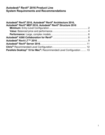
4General settings4.1Mapping settingsThe MAPPING TABLE for IFC export is a table that determines the translation from REVIT nativeentities to IFC entities. This table can be found in Revit Export Options IFC Options.For a correct export ensure that the necessary entities for the desired analysismodel and the correct equivalence between entities are exported.The following table defines which REVIT entities need to be exported to which IFC entitiesdepending on the applications to which the model is to be exported.The goal is NOT to reproduce the entire Revit building in IFC, but rather to extract fromthe model the necessary information to carry out certain actions with specific tools.The graph above shows the amount of information that travels in the IFC (vertical axis), andhow much of this information needs to be interpreted as native by the different disciplinesof the project (horizontal axis).Traditional BIM tools (Revit) are not capable of exporting the space boundaries (IfcSpace)needed, for instance, for accurate thermal analysis as well as the information needed tointerpret thermal/acoustic bridges. However IFC analysis tools are continually improvingand at CYPE we are working on a tool capable of interpreting this missing information toincorporate it automatically into the project. Alternatively, you can use the free BIM tool,CYPE-Revit Interoperability Guide / 10
IFC BUILDER, or CYPECAD MEP, that guarantee a model which exports the maximumamount of information recognisable by the CYPE suite for these types of analysis.CYPE-Revit Interoperability Guide / 11
4.2LevelsIn Revit, it is common to work with several levels on the same floor – at least anarchitectural/ finished floor level, and one structural level. However, most of the analysisand calculation programs in the CYPE suite are designed to work with only one level perfloor – that of its specific function.To avoid excess floors in CYPE programs simply uncheck the “building story” instanceparameter for those levels that are not relevant for the analysis to be carried out.That way, those floors will not be exported and you will be able to continue working onlywith the necessary levels with the specific tool.Be careful when exporting to modelling programs such as CYPECAD MEP or IFCBUILDER – the levels that are not exported cannot be used as a reference for theupper or lower boundaries of the walls.Another alternative solution would be to leave these levels unchecked when importing themodel to calculation programs.CYPE-Revit Interoperability Guide / 12
4.3RoomsThe rooms are one of the most important entities, since they are the basis for many of thecalculations and analyses that can be performed on the BIM model. It will be essential todefine them correctly in order to ensure their accurate export and analysis by applying thefollowing measures:1.Deleting unplaced rooms and spaces.When a room is deleted from any view in Revit it is deleted from the 3D space but itremains present in the project. To completely delete a room in a Revit project it needs tobe done from the schedule. In order to do this, go to View Create Schedule, and createa schedule/quantities table including at least the area. The rooms that are not placed onthe floor will have the value “not placed”. From here they can be deleted, removing themcompletely from the project.CYPE-Revit Interoperability Guide / 13
2.Adjusting the upper room boundary to the lower edge of the upper slab.Currently, Revit’s IFC 4 exporter has limitations when exporting rooms bounded by floorsand ceilings. As opposed to IFC 2x3, it is not able to correctly “trim” the shape of the roomwith its horizontal bounding elements. This means that after exporting the IfcSpace willignore its clash with the slabs. Therefore, to ensure that the volume of the room is correctwhen exported to IfcSpace, a higher negative offset equal to the thickness of the slab mustbe entered. This consideration is only necessary for the development of thermal andacoustic studies.CYPE-Revit Interoperability Guide / 14
3.Checking that the volume of the rooms are being computed.To guarantee that the areas and volumes correctly export to IFC, it is advisable to go toArchitecture Room and area and click and open the dropdown menu Area andvolume computations. Once you have accessed the area and volume computations menuthe “areas and volumes” and “at wall finish” options should be marked.CYPE-Revit Interoperability Guide / 15
4.4WallsIt is advisable to observe the following guidelines to ensure that the walls are correctlyexported from Revit to IFC and that the entities are legible by CYPE software.1.The use of upper and lower constraints for slabs and roofs, avoiding the modificationof the wall profile sketch.2.It is recommended that the walls go from level to level and that there is a wall perfloor. This is especially important when exporting to modelling programs like CYPECADMEP or IFC BUILDER. Otherwise the results of the import in these programs may beunpredictable.3.The use of the wall opening by face tool instead of drawing openings in the sketch ofthe wall.4.It is imperative that the walls are a single integral element in layers- as is outlined inAutodesk’s official documentation. It is not recommended to work with exportedmodels where each wall layer has been modelled as a separate and independent walltype/instance.5.It is preferable to create linear walls instead of walls by face. If the export is carried outto non-modelling programs (like CYPECAD MEP or IFC BUILDER), it will also be possibleto export more complex walls, with the limitations inherited from Revit's IFC exporterdeveloped by Autodesk.CYPE-Revit Interoperability Guide / 16
6.The correct definition of the function type parameter (exterior/interior) of all the wallsaccording to whether they are enclosure or partition walls (for thermal or acousticanalysis programs).CYPE-Revit Interoperability Guide / 17
4.5FloorsThe floors are usually defined by perimeter. As with walls and roofs, it is best to modeltrying to obtain shapes that can be generated in IFC by simple extrusion. To this end, it isrecommended to:1.Use the floor by definition of boundary lines instead of “floor by face”, although the lastoption will also be possible in non-modelling programs.2.Avoid sloped floors that exceed levels. In this case it would be advisable to create anindependent sloped floor in each level, with the meeting points of the floors being atthe upper and lower edges of the respective levels. This is especially relevant whenexporting to modelling programs such as CYPECAD MEP or IFC BUILDER.3.It is recommended to avoid the use of modifications of sub-elements to create slopes,since this could compromise the geometric condition of the parallelepiped floor.Instead, for sloped floors the definition of the family’s inherent slope arrow isrecommended.CYPE-Revit Interoperability Guide / 18
4.6RoofsFor the same reasons stated in previous sections, it is important to model in such a waythat the IFC file can read the entities as simple extrusion profiles.To this end and to optimise the best communication between programs, it isrecommended to employ, as much as possible, the following modelling practices:In general:1.Create the roofs from the “Roofs” group and not from the “Floors” group. This will allowthermal/acoustic analysis programs to be able to distinguish between both elementsand correctly carry out the analyses.2.It is recommended to create roofs by footprint and not by extrusion.3.Associate the roofs to levels to be exported, avoiding gaps as much as possible.4.Sub-elements defined to divide hips or to simulate the evacuation slopes into flat roofswill not be considered. This slope entered in Revit is not considered as useful data forfurther calculations and analysis.5.When exporting to modelling programs such as CYPECAD MEP or IFC Builder, slopedroofs must not exceed levels (e.g. placing the base at level 1 and the roof ridge at level3); ideally, they will be contained within the same level (base at level 1 and roof ridge atlevel 2). Otherwise their relationship with the walls linked to them will beunpredictable.CYPE-Revit Interoperability Guide / 19
4.7Plumbing fixturesThe plumbing fixtures are a fundamental part of the architectural model, the reading ofwhich is essential in order to be able to carry out the analysis and modelling of hydraulicinstallations, as well as other discipline installations such as the shower or bath zones tolocate the electrical outlets in the bathroom.For this reason, when exporting from REVIT using the plugin, each plumbing fixture mustbe differentiated. In this case, REVIT does not consider this option in its IFC export settings.For example, in REVIT the plumbing fixtures are all the same when exported in addition tothem being assigned an incorrect IFC entity, and no distinction is made beyond thiscategory:Therefore, the user will be responsible for assigning the distinction between the plumbingfixtures by creating two shared or instance project parameters, which will have priorityover the IFC export settings, and are the following:-IfcExportAs-IfcExportTypeThe first one will define the IFC entity whilst the second will define the IFC type.CYPE-Revit Interoperability Guide / 20
The difference between project parameters and shared parameters is that projectparameters only appear in the project being used whilst shared parameters can beassigned to various projects.To create these parameters, in the REVIT program go to the top browser in theManagement tab and in the Configuration area click on the shared parameters or projectparameters button:Next, follow the steps for shared parameters. Once you have clicked on the sharedparameters button, you will have to create a group of parameters in the pop-up windowotherwise you will not be able to create the shared parameters. This group is given a nameby the user. In this case it will be called IfcExportAs:CYPE-Revit Interoperability Guide / 21
Once this has been done, create a new group:This now allows the necessary parameters to be created. These will be text typeparameters:CYPE-Revit Interoperability Guide / 22
Once these parameters have been created, go to the project parameters and add them:CYPE-Revit Interoperability Guide / 23
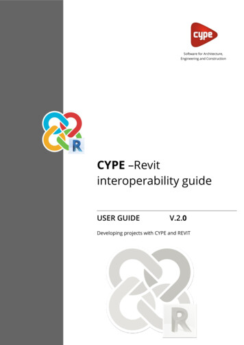
These parameters are instance parameters that will be grouped into IFC parameters andapplied to the family categories to be exported by specifying more than what is included inthe IFC export configuration, such as the plumbing fixtures for example:Once the parameters have been created, both the IFC entity and the IFC type must beassigned to each of the hydraulic elements. The entities and types for the differentplumbing fixtures are defined in the IFC standard:Entity IFCType IFCWash nalBIDETSinkIfcSanitaryTerminalSINKWashing rIfcElectricApplianceDISHWASHERCYPE-Revit Interoperability Guide / 24
It is very important to enter the entities and types with the corresponding capital and lowercase letters.Finally, as this is an instance parameter, it will have to be entered element by element. As aquick solution, since in a project there are many elements that are the same, by rightclicking on one of them and clicking select all instances in the whole project, all theelements of the same type can be selected at the same time:Once selected the two parameters will be filled in:Once all of the plumbing fixtures have been defined, by exporting them they can be readby all programs that require it, such as the CYPEPLUMBING programs (Water Systems andSanitary Systems), among others.CYPE-Revit Interoperability Guide / 25
4.8LinksOne of the limitations of Revit’s IFC exporter is the export of links to IFC.The exporter has many problems with the geolocation of links (correct export whencoordinates are referenced to the Reference Point), and their correct relative positioning ifthey are moved or rotated. As for links where symmetry has been applied it does not evenwork.Therefore, the best way to guarantee a correct and stable export if the project sharesReference Point Coordinates will be to bind all the links that you want to bring to IFC andexport the unified project. This can be done in a separately saved temporary file whosepurpose is the correct export to IFC. To attach, select the link and click on Modify Link Bind.The binding of all the links can be difficult at times, since large projects can contain a greatnumber of objects and geometry and Revit is not capable of supporting many elementssimultaneously due to excessive RAM usage. In these cases you must be bear in mind thatthe important thing is not to transfer the whole model to IFC but only the elementsrelevant to what you want to achieve. It is therefore recommended to delete all categoriesthat do not serve this purpose, optimising the file’s entities and being able to finally carryout the binding of all the links.In the case of other types of shared coordinates they can be exported and the pluginwill unify all Revit links in a single IFC.CYPE-Revit Interoperability Guide / 26
4.9Central and local models; worksetsIn the case of models where collaboration between users is taking place, it is possible toexport to IFC from any of the project’s local files. However, in order to avoid possible issuesand errors with Revit’s IFC exporter due to the user’s ownership permissions for theworksets where the entities to be exported are located, a good practice is to create atemporary copy of the local file that is detached from the central file. This can be done byopening the file from Revit’s file opening manager, where the box “detach from central”must be checked. Ideally, the worksets will also be discarded.This temporary file will be needed only when exporting, and it only needs to be createdonce. Once the IFC file has been exported with the necessary entities and the correctimport has been checked in the corresponding specific CYPE applications, the temporarydetached .rvt file can be deleted. It is important to carry out the export with the free CYPEfor Revit PLUGIN and following all the guidelines in this guide to guarantee an optimalinteroperability.To integrate the information generated in CYPE tools into the workflow of teams that workcollaboratively in Revit, simply create new IFC files from those specific applicationscontaining the necessary technical information and code justifications, which can then belinked back to Revit from any of the local files using the “Link IFC” tool within thecorrespondi
CYPE-Revit Interoperability Guide / 4 1 Introduction This guide establishes guidelines for the optimum communication between the architectural modelling application REVIT, and CYPE's specialist technical programs. This communication is based on the. IFC. format (acronym for INDUSTRY FOUNDATION CLASSES). IFC is an