Transcription
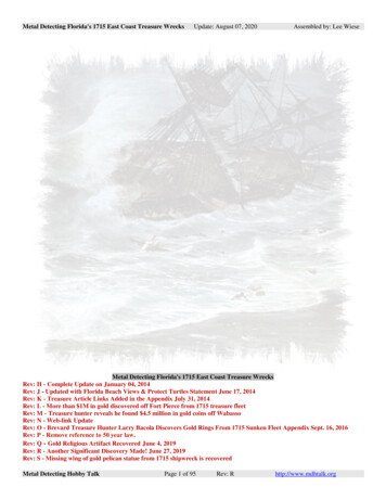
Technical Data1715 Redundant I/O System SpecificationsSystem Module, Catalog Numbers 1715-AENTR, 1715-IB16D, 1715-OB8DE,1715-IF16, 1715-OF8IBase Unit, Catalog Numbers 1715-A2A, 1715-A3IOTermination Assembly, Catalog Numbers 1715-TASIB16D, 1715-TADIB16D, 1715-TAS0B8DE, 1715-TADOB8DE, 1715-TASIF16,1715-TADIF16, 1715-TASOF8, 1715-TADOF8Accessory, Catalog Numbers 1715-N2S, 1715-N2T, 1715-C2CH1 CH1 CH1 CH1TERMINAL IDENTITYCH1 CH1 CH1 CH1AOTADual.Module StatusRedundancy StatusNetwork StatusRack StatusRack StatusEthernet 1Ethernet 2Ethernet 1Ethernet 2ResetResetCH1 CH1 CH1 CH1CH1 CH1 CH1 CH1CH1 CH1 CH1 CH1AOTADual.HealthyReadyRunChannel 00Channel 01Channel 02Channel 03Channel 04Channel 05Channel 06Channel 07TERMINAL IDENTITYCH1 CH1 CH1 CH1CH1 CH1 CH1 nChannel 00Channel 01Channel 02Channel 03Channel 04Channel 05Channel 06Channel 07Channel 00Channel 01Channel 02Channel 03Channel 04Channel 05Channel 06Channel 07Channel 08Channel 09Channel 10Channel 11Channel 12Channel 13Channel 14Channel 15Channel 08Channel 09Channel 10Channel 11Channel 12Channel 13Channel 14Channel 15IO BASE1715-A310Module StatusRedundancy StatusNetwork StatusTERMINAL IDENTITYCH1 CH1 CH1 CH1TERMINAL IDENTITYTERMINAL IDENTITYCH1 CH1 CH1 CH1CH1 CH1 CH1 CH1CH1 CH1 CH1 CH1CH1 CH1 CH1 nChannel 00Channel 01Channel 02Channel 03Channel 04Channel 05Channel 06Channel 07Channel 00Channel 01Channel 02Channel 03Channel 04Channel 05Channel 06Channel 07Channel 00Channel 01Channel 02Channel 03Channel 04Channel 05Channel 06Channel 07Channel 08Channel 09Channel 10Channel 11Channel 12Channel 13Channel 14Channel 15Channel 08Channel 09Channel 10Channel 11Channel 12Channel 13Channel 14Channel 15HealthyReadyRunIO BASE1715-A310TERMINAL IDENTITYTopicPageConformal Coating Standards21715-AENTR EtherNet/IP Adapter and 1715-A2A Module Base31715-IB16D Digital Input Module, 1715-A3IO Module Base, and Termination Assemblies61715-OB8DE Digital Output Module, 1715-A3IO Module Base, and Termination Assemblies91715-IF16 Analog Input Module, 1715-A3IO Module Base, and Termination Assemblies121715-OF8I Analog Output Module, 1715-A3IO Module Base, and Termination Assemblies15Additional Resources18
1715 Redundant I/O System SpecificationsTable 1 - 1715 Adapter and Module I/O Base UnitsAttribute1715-A2A1715-A3IOModules supportedRequired for 2 x 1715-AENTR modulesSupports: 1 I/O bus 8 I/O base units (1715-A3IO) 24 I/O modulesAs many as 3 I/O modulesWeight, approx283 g (9.98 oz)220 g (7.76 oz)Dimensions (H x W x D), approx224 x 84 x 30 mm (8.82 x 3.31 x 1.18 in.)233 x 126 x 18 mm (6.5 x 1.625 x 4.25 in.)Table 2 - 1715 Termination AssembliesAttribute1715-TASIB16D, 1715-TADIB16D1715-TASOB8DE, 1715-TADOB8DE1715-TASIF16, 1715-TADIF161715-TASOF8, 1715-TADOF8Modules ht, approx133 g (4.69 oz), 260 g (9.17 oz)133 g (4.69 oz), 260 g (9.17 oz)133 g (4.69 oz), 260 g (9.17 oz)133 g (4.69 oz), 260 g (9.17 oz)Fuses50 mA for each channel5 A for each supply50 mA per channelNoneScrew torque0.5 N m (0.37 lb ft)Screwdriver widthFlathead 0.4 x 2.0 m (0.0156 x 0.0781 in.)Dimensions(H x W x D), approx1715-TASIB16D, 1715-TASOB8DE, 1715-TASIF16, 1715-TASOF8: 132 x 42 mm (5.25 x 1.65 in.)1715-TADIB16D, 1715-TADOB8DE, 1715-TADIF16, 1715-TADOF8: 132 x 84 mm (5.25 x 3.375 in.)Conformal Coating StandardsThe 1715 modules are conformally coated and meet the following standards: ANSI/ISA-S71.04-2013; Class G1, G2, and G3 environments CEI IEC 60654-4:1987; Class 1, 2, and 3 Environments UL746E MIL-1-46058C to ASTM-G21 (Tropicalization and fungicide)2Rockwell Automation Publication 1715-TD001E-EN-P - January 2017
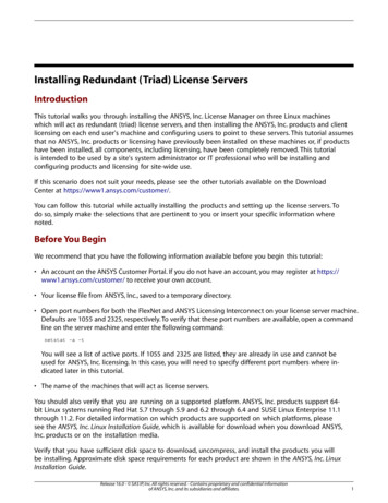
1715 Redundant I/O System Specifications1715-AENTR EtherNet/IP Adapter and 1715-A2A Module Base1715-AENTR Power Wiring0V 24V DCPwr10V 24V DCPwr2Table 3 - Technical Specifications - 1715-AENTR EtherNet/IP Adapter and 1715-A2A Module BaseAttribute1715-AENTR and 1715-A2AModules supported, max24 per adapter pairOperating voltage range, supply power and/or current ratings1715-AENTR backplane: 380 mA @18 32V DC1715-A2A input power: 10.4 A total max/400 mA max per slot @ 18 32V DCFor fault-tolerant applications, the I/O module power is less than 3.2 APower dissipation8 W max, per adapterIsolation voltage50V (continuous), basic insulation type, Ethernet ports to backplane and Ethernet ports to DCpower portsNo isolation between individual Ethernet portsNo isolation between DC power portsType tested @ 500V AC for 60 sBase unit1715-A2A (2-slot adapter base unit)Weight, approx1715-AENTR module: 420 g (14.82 oz)1715-A2A base unit: 283 g (9.98 oz)Fuse, type4 A, 125V, Type TWiring category2 - on power ports2 - on communication ports(1)Wire size1715-A2A DC Power connections: single 2.5 mm2 (12 AWG) solid or stranded copper wire rated at85 C (185 F) or greater,7 mm (9/32 in.) strip length1715-A2A Ground connection: 4 mm2 (10 AWG) minWire type1715-A2A Ethernet connections:Shielded RJ45 connector according to IEC60603-7, 2-pair or 4-pair shieldedCategory 5e min cable according to TIA 568-B1 or shielded Category 5 cable according to ISO/IEC 24702North American temperature codeT4IEC temperature codeT4Enclosure type ratingNone (open-style)(1) Use this conductor category information for planning conductor routing as described in the system level installation manual. See the Industrial Automation Wiring and Grounding Guidelines, publication1770-4.1.Rockwell Automation Publication 1715-TD001E-EN-P - January 20173
1715 Redundant I/O System SpecificationsTable 4 - Environmental Specifications - 1715-AENTR EtherNet/IP Adapter and 1715-A2A Module BaseAttribute1715-AENTR and 1715-A2ATemperature, operatingIEC 60068-2-1 (Test Ad, Operating Cold),IEC 60068-2-2 (Test Bd, Operating Dry Heat),IEC 60068-2-14 (Test Nb, Operating Thermal Shock)-25 60 C (-13 140 F)Temperature, surrounding air max60 C (140 F)Temperature, nonoperatingIEC 60068-2-1 (Test Ab, Unpackaged Nonoperating Cold),IEC 60068-2-2 (Test Bb, Unpackaged Nonoperating Dry Heat),IEC 60068-2-14 (Test Na, Unpackaged Nonoperating Thermal Shock)-40 85 C (-40 185 F)Relative humidityIEC 60068-2-30 (Test Db, Unpackaged Nonoperating Damp Heat)10 95% noncondensingVibrationIEC 60068-2-6 (Test Fc, Operating)2 g @ 10 500 HzShock, operatingIEC 60068-2-27 (Test Ea, Unpackaged Shock)Din rail mount: 25 gPanel mount: 30 gShock, nonoperatingIEC 60068-2-27 (Test Ea, Unpackaged Shock)Installed: 30 gUninstalled: 50 g (with slot fillers)EmissionsCISPR 11 (IEC 61000-6-4)Class AESD immunityIEC 61000-4-26 kV contact discharges8 kV air dischargesRadiated RF immunityIEC 61000-4-320V/m with 1 kHz sine-wave 80% AM from 80 1000 MHz10V/m with 1 kHz sine-wave 80% AM from 1000 2000 MHz10V/m with 200 Hz 50% Pulse 100% AM @ 900 MHz10V/m with 200 Hz 50% Pulse 100% AM @ 1890 MHz3V/m with 1 kHz sine-wave 80% AM from 2000 2700 MHzEFT/B immunityIEC 61000-4-4 3 kV at 5 kHz on power ports 2 kV at 5 kHz on shielded Ethernet portsSurge transient immunityIEC 61000-4-5 1 kV line-line (DM) and 2 kV line-earth (CM) on power ports 2 kV line-earth (CM) on shielded Ethernet portsConducted RF immunityIEC 61000-4-610V rms with 1 kHz sine-wave 80% AM from 150 kHz 80 MHzTable 5 - Certifications - 1715-AENTR EtherNet/IP Adapter and 1715-A2A Module Base4Certification(1)1715-AENTR and 1715-A2AcULusUL Listed Industrial Control Equipment, certified for US and Canada. See UL File E341697.UL Listed for Class I, Division 2 Group A,B,C,D Hazardous Locations, certified for U.S. and Canada.See UL File E251761.CEEuropean Union 2004/108/EC EMC Directive, compliant with: EN 61326-1; Meas./Control/Lab., Industrial Requirements EN 61000-6-2; Industrial Immunity EN 61000-6-4; Industrial Emissions EN 61131-2; Programmable Controllers (Clause 8, Zone A & B)C-TickAustralian Radiocommunications Act, compliant with:AS/NZS CISPR 11; Industrial EmissionsExEuropean Union 94/9/EC ATEX Directive, compliant with: EN 60079-15; Potentially Explosive Atmospheres, Protection ‘n’ EN 60079-0; General Requirements II 3 G Ex nA IIC T4 Gc X DEMKO 11 ATEX 7928686XRockwell Automation Publication 1715-TD001E-EN-P - January 2017
1715 Redundant I/O System SpecificationsTable 5 - Certifications - 1715-AENTR EtherNet/IP Adapter and 1715-A2A Module BaseCertification(1)1715-AENTR and 1715-A2AIECExIECEx Hazardous Location approval, compliant with: IEC 60079-0: Ed 6 Explosive Atmospheres - General Requirements IEC 60079-15: Ed 4 Explosive Atmospheres - Protection 'n' IECEx UL 15.0032XKCKorean Registration of Broadcasting and Communications Equipment, compliant with:Article 58-2 of Radio Waves Act, Clause 3EtherNet/IPODVA conformance tested to EtherNet/IP specificationsFunctional SafetyTÜV Certified for Functional Safety(2):Capable of SIL 2 according to EN 62061, IEC 61508, and EN 61326-3-1(1) When marked. See the Product Certification link at http://www.ab.com for Declarations of Conformity, Certificates, and other certification details.(2) When used with specified firmware revisions.Rockwell Automation Publication 1715-TD001E-EN-P - January 20175
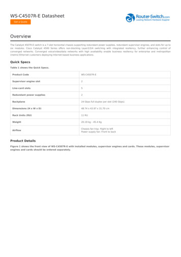
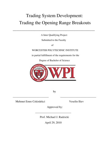
1715 Redundant I/O System Specifications1715-IB16D Digital Input Module, 1715-A3IO Module Base, and TerminationAssembliesLine Monitored Input 24V DCDIGITAL hannel 00Channel 01Channel 02Channel 03Channel 04Channel 05Channel 06Channel 0750 mAShield(if used)5.11K ΩTerminalBlocksOVChannel 08Channel 09Channel 10Channel 11Channel 12Channel 13Channel 14Channel 15Standard Input 24V DCTerminationAssembly32065-M50 mAShield(if used)5.11K ΩTerminalBlocks32092-MOVTable 6 - Technical Specifications - 1715-IB16D Digital Input Module, 1715-A3IO Module Base, and 1715-TASIB16D, 1715-TADIB16D TerminationAssemblies6Attribute1715-IB16D, 1715-A3IO, 1715-TASIB16D, 1715-TADIB16DOperating voltage range, supply power and/or current ratings1715-IB16D backplane: 260 mA @ 18 32V DC1715-TASIB16D, 1715-TAD8B16D: 6.5 mA per channel @ 0 32V DCSlew rate, max3600 V/s(1)Translation rate, max1/(Application scan time 10 ms) Hz(1)Power dissipationSystem 4.0 W max.Field loop: 0.2 W per field loop max.Isolation voltage50V (continuous), basic insulation type, I/O ports to backplaneNo isolation between individual I/O ports if the 1715-TASIB16D termination assembly is fitted50V isolation between individual ports if 1715-TADIB16D termination assembly is fittedType tested at 500V AC for 60 sWeight, approx1715-IB16D: 360 g (12.70 oz)I/O base unit: 133 g (5 oz)Termination assembly: 133 g (5 oz), 260 g (10 oz)Dimensions (H x W x D), approx166 x 42 x 118 mm (6.5 x 1.625 x 4.625 in.)Wire size1715-TASIB16D, 1715-TADIB16D connections:0.33 1.5 mm2 (22 16 AWG) solid or stranded copper wire rated at 85 C (185 F), or greaterRockwell Automation Publication 1715-TD001E-EN-P - January 2017
1715 Redundant I/O System SpecificationsTable 6 - Technical Specifications - 1715-IB16D Digital Input Module, 1715-A3IO Module Base, and 1715-TASIB16D, 1715-TADIB16D TerminationAssembliesAttribute1715-IB16D, 1715-A3IO, 1715-TASIB16D, 1715-TADIB16DWiring category2 - on signal ports(2)Fuse, type50 mA, 125V, Type TNorth American temperature codeT4IEC temperature codeT4Enclosure typeNone (open-style)(1) The input slew can exceed the specified levels if the duration of the transgression is less than the process safety time of the configured module.Transgression of the slew rate limits identified previously can lead to channel failure that results from diagnostics that are otherwise designed to ensure channels are operating within their defined safetyaccuracy.(2) Use this conductor category information for planning conductor routing as described in the system-level installation manual. See the Industrial Automation Wiring and Grounding Guidelines, publication1770-4.1.Table 7 - Environmental Specifications - 1715-IB16D Digital Input, 1715-A3IO Module Base, and 1715-TASIB16D, 1715-TADIB16D TerminationAssembliesAttribute1715-IB16D, 1715-A3IO, 1715-TASIB16D, 1715-TADIB16DTemperature, operatingIEC 60068-2-1 (Test Ad, Operating Cold),IEC 60068-2-2 (Test Bd, Operating Dry Heat),IEC 60068-2-14 (Test Nb, Operating Thermal Shock)-25 70 C (-13 158 F)Temperature, surrounding air, max70 C (158 F)Temperature, nonoperatingIEC 60068-2-1 (Test Ab, Unpackaged Nonoperating Cold),IEC 60068-2-2 (Test Bb, Unpackaged Nonoperating Dry Heat),IEC 60068-2-14 (Test Na, Unpackaged Nonoperating Thermal Shock)-40 85 C (-40 185 F)Relative humidityIEC 60068-2-30 (Test Db, Unpackaged Nonoperating Damp Heat)10 95% noncondensingVibrationIEC 60068-2-6 (Test Fc, Operating)2 g @ 10 500 HzShock, operatingIEC 60068-2-27 (Test Ea, Unpackaged Shock)DIN rail mount: 25 gPanel mount: 30 gShock, nonoperatingIEC 60068-2-27 (Test Ea, Unpackaged Shock)Installed: 30 gUninstalled: 50 g (with slot fillers)EmissionsCISPR 11 (IEC 61000-6-4)Class AESD immunityIEC 61000-4-26 kV contact discharges8 kV air dischargesRadiated RF immunityIEC 61000-4-320V/m with 1 kHz sine-wave 80% AM from 80 1000 MHz10V/m with 1 kHz sine-wave 80% AM from 1000 2000 MHz10V/m with 200 Hz 50% Pulse 100% AM @ 900 MHz10V/m with 200 Hz 50% Pulse 100% AM @ 1890 MHz3V/m with 1 kHz sine-wave 80% AM from 2000 2700 MHzEFT/B immunityIEC 61000-4-4 2 kV @ 5 kHz on signal portsSurge transient immunityIEC 61000-4-5 1 kV line-line (DM) and 2 kV line-earth (CM) on signal portsConducted RF immunityIEC 61000-4-610V rms with 1 kHz sine-wave 80% AM from 150 kHz 80 MHzRockwell Automation Publication 1715-TD001E-EN-P - January 20177
1715 Redundant I/O System SpecificationsTable 8 - Certifications - 1715-IB16D Digital Input, 1715-A3IO Module Base, and 1715-TASIB16D, 1715-TADIB16D Termination AssembliesCertification(1)1715-IB16D, 1715-A3IO, 1715-TASIB16D, 1715-TADIB16DcULusUL Listed Industrial Control Equipment, certified for US and Canada. See UL File E341697.UL Listed for Class I, Division 2 Group A,B,C,D Hazardous Locations, certified for U.S. and Canada. SeeUL File E251761.CEEuropean Union 2004/108/EC EMC Directive, compliant with: EN 61326-1; Meas./Control/Lab., Industrial Requirements EN 61000-6-2; Industrial Immunity EN 61000-6-4; Industrial Emissions EN 61131-2; Programmable Controllers (Clause 8, Zone A & B)C-TickAustralian Radiocommunications Act, compliant with:AS/NZS CISPR 11; Industrial EmissionsExEuropean Union 94/9/EC ATEX Directive, compliant with: EN 60079-15; Potentially Explosive Atmospheres, Protection ‘n’ EN 60079-0; General Requirements II 3 G Ex nA IIC T4 Gc X DEMKO 11 ATEX 7928686XIECExIECEx Hazardous Location approval, compliant with: IEC 60079-0: Ed 6 Explosive Atmospheres - General Requirements IEC 60079-15: Ed 4 Explosive Atmospheres - Protection 'n' IECEx UL 15.0032XKCKorean Registration of Broadcasting and Communications Equipment, compliant with:Article 58-2 of Radio Waves Act, Clause 3Functional SafetyTÜV Certified for Functional Safety(2):Capable of SIL 2 according to EN 62061, IEC 61508, and EN 61326-3-1(1) When marked. See the Product Certification link at http://www.ab.com for Declarations of Conformity, Certificates, and other certification details.(2) When used with specified firmware revisions.8Rockwell Automation Publication 1715-TD001E-EN-P - January 2017
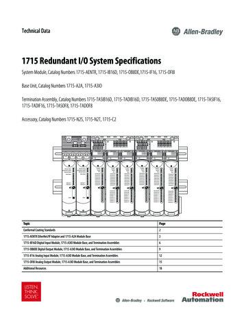
1715 Redundant I/O System Specifications1715-OB8DE Digital Output Module, 1715-A3IO Module Base, and TerminationAssembliesStandard OutputDIGITAL OUTPUT1715-OB8DEHealthyReadyRunChannel 00Channel 01Channel 02Channel 03Channel 04Channel 05Channel 06Channel 0733002-M32090-MTable 9 - Technical Specifications - 1715-OB8DE Digital Output Module, 1715-A3IO Module Base, and 1715-TASOB8DE, 1715-TADOB8DE TerminationAssembliesAttribute1715-OB8DE, 1715-A3IO, 1715-TASOB8DE, 1715-TADOB8DEOperating voltage range, supply power and/or current ratings1715-OB8DE backplane: 165 mA @ 18 32V DC1715-TASOB8DE, 1715-TADOB8DE I/O: 0.5 A per channel @ 18 32V DCField voltage slew rate, max150 V/s(1),(2)De-energized output voltage slew rate, max12 V/ms(3)Energized output current slew rate, max0.9 A/ms(3)Power dissipationSystem: 3.0 W maxField Loop: 0.17 W per field loopIsolation voltage50V (continuous), basic insulation type, I/O ports to backplaneNo isolation between individual I/O portsType tested at 500V AC for 60 sWeight, approx1715-OB8DE module: 290 g (10.23 oz)I/O base unit: 133 g (5 oz)Termination assembly: 133 g (5 oz), 260 g (10 oz)Dimensions (H x W x D), approx166 x 42 x 118 mm (6.5 x 1.625 x 4.625 in.)Wire size1715-TASOB8DE, 1715-TADOB8DE connections:Single 0.75 1.5 mm2 (18 16 AWG) solid or stranded copper wire rated at 85 C (185 F), orgreaterWiring category2 - on signal ports(4)Fuse, type1715-TASOB8DE, 1715-TADOB8DE I/O: 10 A, 125V, Type F1715-TASOB8DE, 1715-TADOB8DE I/O Power Source: 5 A max, 32V DC, minPilot duty rating16VA, 1.5 inrushRockwell Automation Publication 1715-TD001E-EN-P - January 20179
1715 Redundant I/O System SpecificationsTable 9 - Technical Specifications - 1715-OB8DE Digital Output Module, 1715-A3IO Module Base, and 1715-TASOB8DE, 1715-TADOB8DE TerminationAssembliesAttribute1715-OB8DE, 1715-A3IO, 1715-TASOB8DE, 1715-TADOB8DENorth American temperature codeT4IEC temperature codeT4Enclosure typeNone (open-style)(1) Limit not applicable if all outputs are energized.(2) Limit not applicable if perturbations are less than 2.0 Vpp or last less than 3 minutes in any 60 minute period.(3) Limit not applicable to transgressions that last less than the process safety time configured for the module.Transgression of the slew rate limits identified previously can lead to channel failure that results from diagnostics that are otherwise designed to ensure channels are operating within their defined safetyaccuracy.(4) Use this conductor category information for planning conductor routing as described in the system-level installation manual. See the Industrial Automation Wiring and Grounding Guidelines, publication1770-4.1.Table 10 - Environmental Specifications - 1715-OB8DE Digital Output Module, 1715-A3IO Module Base, and 1715-TASOB8DE, 1715-TASOB8DETermination AssembliesAttribute1715-OB8DE, 1715-A3IO, 1715-TASOB8DE, 1715-TADOB8DETemperature, operatingIEC 60068-2-1 (Test Ad, Operating Cold),IEC 60068-2-2 (Test Bd, Operating Dry Heat),IEC 60068-2-14 (Test Nb, Operating Thermal Shock)-25 70 C (-13 158 F)Temperature, surrounding air, max70 C (158 F)Temperature, nonoperatingIEC 60068-2-1 (Test Ab, Unpackaged Nonoperating Cold),IEC 60068-2-2 (Test Bb, Unpackaged Nonoperating Dry Heat),IEC 60068-2-14 (Test Na, Unpackaged Nonoperating Thermal Shock)-40 85 C (-40 185 F)Relative humidityIEC 60068-2-30 (Test Db, Unpackaged Nonoperating Damp Heat)10 95% noncondensingVibrationIEC 60068-2-6 (Test Fc, Operating)2 g @ 10 500 HzShock, operatingIEC 60068-2-27 (Test Ea, Unpackaged Shock)DIN rail mount: 25 gPanel mount: 30 gShock, nonoperatingIEC 60068-2-27 (Test Ea, Unpackaged Shock)Installed: 30 gUninstalled: 50 g (with slot fillers)EmissionsCISPR 11 (IEC 61000-6-4)Class AESD immunityIEC 61000-4-26 kV contact discharges8 kV air dischargesRadiated RF immunityIEC 61000-4-320V/m with 1 kHz sine-wave 80% AM from 80 1000 MHz10V/m with 1 kHz sine-wave 80% AM from 1000 2000 MHz10V/m with 200 Hz 50% Pulse 100% AM @ 900 MHz10V/m with 200 Hz 50% Pulse 100% AM @ 1890 MHz3V/m with 1 kHz sine-wave 80% AM from 2000 2700 MHzEFT/B immunityIEC 61000-4-4 2 kV @ 5 kHz on signal portsSurge transient immunityIEC 61000-4-5 1 kV line-line (DM) and 2 kV line-earth (CM) on signal portsConducted RF immunityIEC 61000-4-610V rms with 1 kHz sine-wave 80% AM from 150 kHz 80 MHz10Rockwell Automation Publication 1715-TD001E-EN-P - January 2017
1715 Redundant I/O System SpecificationsTable 11 - Certifications - 1715-OB8DE Digital Output Module, 1715-A3IO Module Base, and 1715-TASOB8DE, 1715-TASOB8DE TerminationAssembliesCertification(1)1715-OB8DE, 1715-A3IO, 1715-TASOB8DE, 1715-TADOB8DEcULusUL Listed Industrial Control Equipment, certified for US and Canada. See UL File E341697.UL Listed for Class I, Division 2 Group A,B,C,D Hazardous Locations, certified for U.S. and Canada. See UL File E251761.CEEuropean Union 2004/108/EC EMC Directive, compliant with: EN 61326-1; Meas./Control/Lab., Industrial Requirements EN 61000-6-2; Industrial Immunity EN 61000-6-4; Industrial Emissions EN 61131-2; Programmable Controllers (Clause 8, Zone A & B)C-TickAustralian Radiocommunications Act, compliant with:AS/NZS CISPR 11; Industrial EmissionsExEuropean Union 94/9/EC ATEX Directive, compliant with: EN 60079-15; Potentially Explosive Atmospheres, Protection ‘n’ EN 60079-0; General Requirements II 3 G Ex nA IIC T4 Gc X DEMKO 11 ATEX 7928686XIECExIECEx Hazardous Location approval, compliant with: IEC 60079-0: Ed 6 Explosive Atmospheres - General Requirements IEC 60079-15: Ed 4 Explosive Atmospheres - Protection 'n' IECEx UL 15.0032XKCKorean Registration of Broadcasting and Communications Equipment, compliant with:Article 58-2 of Radio Waves Act, Clause 3Functional SafetyTÜV Certified for Functional Safety(2):Capable of SIL 2 according to EN 62061, IEC 61508, and EN 61326-3-1(1) When marked. See the Product Certification link at http://www.ab.com for Declarations of Conformity, Certificates, and other certification details.(2) When used with specified firmware revisions.Rockwell Automation Publication 1715-TD001E-EN-P - January 201711
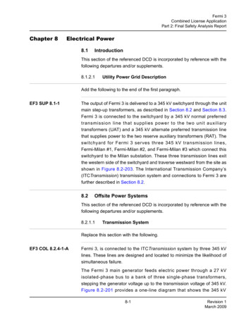
1715 Redundant I/O System Specifications1715-IF16 Analog Input Module, 1715-A3IO Module Base, and TerminationAssemblies3-wire Analog Input2-wire Analog InputANALOG INPUT1715-IF16 24V DC 24V DCHealthyReadyRunChannel 00Channel 01Channel 02Channel 03Channel 04Channel 05Channel 06Channel 07TerminationAssembly4-20 mATerminationAssembly4-20 mA50 mAShield(if used)TerminalBlocks120 ΩTerminalBlocksOVOV4-wire Analog InputChannel 08Channel 09Channel 10Channel 11Channel 12Channel 13Channel 14Channel 15 V 5TerminationAssembly-V 54-20 mA50 mAShield(if used)120 ΩTerminalBlocks32091-MOVTable 12 - Performance Criteria for 1715-IF16 Analog Input ModuleAttributeValueData Input value least significant bit0.98 AChannel Measurement Error at 25 ºC (77 ºF) 2 ºC ( 3.6 ºF)After 1 year at 40 ºC (104 ºF)After 2 years at 40 ºC (104 ºF)After 5 years at 40 ºC (104 ºF)0.21% 10 A0.22% 10 A0.23% 10 ATemperature Drift(0.01% 0.3 A) per ºC1250 mAShield(if used)120ΩRockwell Automation Publication 1715-TD001E-EN-P - January 2017
1715 Redundant I/O System SpecificationsTable 13 - Technical Specifications - 1715-IF16 Analog Input Module, 1715-A3IO Module Base, and 1715-TASIF16, 1715-TADIF16 TerminationAssembliesAttribute1715-IF16, 1715-A3IO, 1715-TASIF16, 1715-TADIF16Operating voltage range, supply power and/or current ratings1715-IF16 backplane: 260 mA @ 18 32V DC1715-TASIF16, 1715-TADIF16 I/O: 0 24 mA per channel @ 18 32V DCSlew rate, max700 mA/s(1)Power dissipationSystem 4.0 W max.Field loop: 0.075 W per field loop max.Isolation voltage50V (continuous), basic insulation type, I/O ports to backplaneNo isolation between individual I/O ports if the 1715-TASIF16 termination assembly is fitted50V isolation between individual ports if 1715-TADIIF16 termination assembly is fittedType tested at 500V AC for 60 sInput resolution0.0039 mA/cnt (12 bits over 4 20 mA range)Weight, approx1715-IF16 module: 360 g (12.70 oz)I/O base unit: 133 g (5 oz)Termination assembly: 133 g (5 oz), 260 g (10 oz)Dimensions (H x W x D), approx166 x 42 x 118 mm (6.5 x 1.625 x 4.625 in.)Wire size1715-TASIF16, 1715-TADIF16 I/O connections:Single 0.33 1.5 mm2 (22 16 AWG) solid or stranded shielded copper wire rated at85 C (185 F), or greaterWiring category2 - on shielded signal ports(2)Fuse, type1715-TASIF16, 1715-TADIF16 I/O: 50 mA, 125V, Type TWire typeShieldedNorth American temperature codeT4IEC temperature codeT4Enclosure typeNone (open-style)(1) The input slew can exceed the specified level if the duration of the transgression is less than the process safety time of the configured module.Transgression of the slew rate limits identified previously can lead to channel failure that results from diagnostics that are otherwise designed to ensure channels are operating within their defined safetyaccuracy.(2) Use this conductor category information for planning conductor routing as described in the system-level installation manual. See the Industrial Automation Wiring and Grounding Guidelines, publication1770-4.1.Table 14 - Environmental Specifications - 1715-IF16 Analog Input Module, 1715-A3IO Module Base, and 1715-TASIF16, 1715-TADIF16 TerminationAssembliesAttribute1715-IF16, 1715-A3IO, 1715-TASIF16, 1715-TADIF16Temperature, operatingIEC 60068-2-1 (Test Ad, Operating Cold),IEC 60068-2-2 (Test Bd, Operating Dry Heat),IEC 60068-2-14 (Test Nb, Operating Thermal Shock)-25 70 C (-13 158 F)Temperature, surrounding air, max70 C (158 F)Temperature, nonoperatingIEC 60068-2-1 (Test Ab, Unpackaged Nonoperating Cold),IEC 60068-2-2 (Test Bb, Unpackaged Nonoperating Dry Heat),IEC 60068-2-14 (Test Na, Unpackaged Nonoperating Thermal Shock)-40 85 C (-40 185 F)Relative humidityIEC 60068-2-30 (Test Db, Unpackaged Nonoperating Damp Heat)10 95% noncondensingRockwell Automation Publication 1715-TD001E-EN-P - January 201713
1715 Redundant I/O System SpecificationsTable 14 - Environmental Specifications - 1715-IF16 Analog Input Module, 1715-A3IO Module Base, and 1715-TASIF16, 1715-TADIF16 TerminationAssembliesAttribute1715-IF16, 1715-A3IO, 1715-TASIF16, 1715-TADIF16VibrationIEC 60068-2-6 (Test Fc, Operating)2 g @ 10 500 HzShock, operatingIEC 60068-2-27 (Test Ea, Unpackaged Shock)DIN rail mount: 25 gPanel mount: 30 gShock, nonoperatingIEC 60068-2-27 (Test Ea, Unpackaged Shock)Installed: 30 gUninstalled: 50 g (with slot fillers)EmissionsCISPR 11 (IEC 61000-6-4)Class AESD immunityIEC 61000-4-26 kV contact discharges8 kV air dischargesRadiated RF immunityIEC 61000-4-320V/m with 1 kHz sine-wave 80% AM from 80 1000 MHz10V/m with 1 kHz sine-wave 80% AM from 1000 2000 MHz10V/m with 200 Hz 50% Pulse 100% AM @ 900 MHz10V/m with 200 Hz 50% Pulse 100% AM @ 1890 MHz3V/m with 1 kHz sine-wave 80% AM from 2000 2700 MHzEFT/B immunityIEC 61000-4-4 2 kV @ 5 kHz on shielded signal portsSurge transient immunityIEC 61000-4-5 2 kV line-earth (CM) on shielded signal portsConducted RF immunityIEC 61000-4-610V rms with 1 kHz sine-wave 80% AM from 150 kHz 80 MHzTable 15 - Certifications - 1715-IF16 Analog Input Module, 1715-A3IO Module Base, and 1715-TASIF16, 1715-TADIF16 Termination AssembliesCertification(1)1715-IF16, 1715-A3IO, 1715-TASIF16, 1715-TADIF16cULusULUL Listed Industrial Control Equipment, certified for US and Canada. See UL File E341697.UL Listed for Class I, Division 2 Group A,B,C,D Hazardous Locations, certified for U.S. and Canada. See UL File E251761.CEEuropean Union 2004/108/EC EMC Directive, compliant with: EN 61326-1; Meas./Control/Lab., Industrial Requirements EN 61000-6-2; Industrial Immunity EN 61000-6-4; Industrial Emissions EN 61131-2; Programmable Controllers (Clause 8, Zone A & B)C-TickAustralian Radiocommunications Act, compliant with:AS/NZS CISPR 11; Industrial EmissionsExEuropean Union 94/9/EC ATEX Directive, compliant with: EN 60079-15; Potentially Explosive Atmospheres, Protection ‘n’ EN 60079-0; General Requirements II 3 G Ex nA IIC T4 Gc X DEMKO 11 ATEX 7928686XIECExIECEx Hazardous Location approval, compliant with: IEC 60079-0: Ed 6 Explosive Atmospheres - General Requirements IEC 60079-15: Ed 4 Explosive Atmospheres - Protection 'n' IECEx UL 15.0032XKCKorean Registration of Broadcasting and Communications Equipment, compliant with:Article 58-2 of Radio Waves Act, Clause 3Functional SafetyTÜV Certified for Functional Safety(2):Capable of SIL 2 according to EN 62061, IEC 61508, and EN 61326-3-1(1) When marked. See the Product Certification link at http://www.ab.com for Declarations of Conformity, Certificates, and other certification details.(2) When used with specified firmware revisions.14Rockwell Automation Publication 1715-TD001E-EN-P - January 2017
1715 Redundant I/O System Specifications1715-OF8I Analog Output Module, 1715-A3IO Module Base, and TerminationAssembliesAnalog Output Field Loop CircuitANALOG OUTPUT1715-OF8ISystem 24V DCHealthyReadyRunCH Channel 00Channel 01Channel 02Channel 03Channel 04Channel 05Channel 06Channel 07CHAnalog OutputModuleTerminationAssemblyLoadOVAnalog Output Field Power CircuitSystem 24V DCCH LoadCHAnalog OutputModuleTerminationAssembly32089-MOVTable 16 - Performance Criteria for 1715-OF8I Analog Output ModuleAttributeValueData Input value least significant bit (control)0.98 AData Output value least significant bit (monitor)3.9 AChannel Measurement Error at 25 ºC (77 ºF) 2 ºC ( 3.6 ºF)After 1 year at 40 ºC (104 ºF)After 2 years at 40 ºC (104 ºF)After 5 years at 40 ºC (104 ºF)0.30% 10 A0.35% 10 A0.44% 10 ATemperature drift(0.01% 0.1 A) per ºCRockwell Automation Publication 1715-TD001E-EN-P - January 201715
1715 Redundant I/O System SpecificationsTable 17 - Technical Specifications - 1715-OF8I Analog Output Module, 1715-A3IO Module Base, and 1715-TASOF8I, 1715-TADOF8I TerminationAssembliesAttribute1756-OF8I, 1715-A3IO, 1715-TASOF8, 1715-TADOF8Operating voltage range, supply power and/or current ratings1715-OF8I backplane: 260 mA @ 18 32V DC1715-TASOF8, 1715-TADOF8 I/O: 0 24 mA per channel @ 18 32V DCCompliance voltage slew rate, maxNo limit identified within compliance voltage rangePower dissipationSystem: 3.6 W maxField Loop: 0.64 W per field loopIsolation voltage50V (continuous), basic insulation type, I/O ports to backplane50V isolation between individual I/O portsType tested at 500V AC for 60 sWeight, approx1715-OF8I module: 340 g (11.99 oz)I/O base unit: 133 g (5 oz)Termination assembly: 133 g (5 oz), 260 g (10 oz)Dimensions (H x W x D), approx166 x 42 x 118 mm (6.5 x 1.625 x 4.625 in.)Wire size1715-TASOF8I, 1715-TADOF8I I/O connections:Single 0.33 1.5 mm2 (22 16 AWG) solid or stranded shielded copper wire rated at 85 C (185 F), or greaterWiring category2 - on shielded
IEC 60068-2-27 (Test Ea, Unpackaged Shock) Din rail mount: 25 g Panel mount: 30 g Shock, nonoperating IEC 60068-2-27 (Test Ea, Unpackaged Shock) Installed: 30 g Uninstalled: 50 g (with slot fillers) Emissions CISPR 11 (IEC 61000-6-4) Class A ESD immunity IEC 61000-4-2 6 kV contact discharges 8 kV air disch