Transcription
Quick StartOriginal InstructionsSMC-50 Smart Motor ControllerBulletin150
Important User InformationRead this document and the documents listed in the additional resources section about installation, configuration, andoperation of this equipment before you install, configure, operate, or maintain this product. Users are required tofamiliarize themselves with installation and wiring instructions in addition to requirements of all applicable codes, laws,and standards.Activities including installation, adjustments, putting into service, use, assembly, disassembly, and maintenance arerequired to be carried out by suitably trained personnel in accordance with applicable code of practice.If this equipment is used in a manner not specified by the manufacturer, the protection provided by the equipment maybe impaired.In no event will Rockwell Automation, Inc. be responsible or liable for indirect or consequential damages resulting fromthe use or application of this equipment.The examples and diagrams in this manual are included solely for illustrative purposes. Because of the many variables andrequirements associated with any particular installation, Rockwell Automation, Inc. cannot assume responsibility orliability for actual use based on the examples and diagrams.No patent liability is assumed by Rockwell Automation, Inc. with respect to use of information, circuits, equipment, orsoftware described in this manual.Reproduction of the contents of this manual, in whole or in part, without written permission of Rockwell Automation,Inc., is prohibitedThroughout this manual, when necessary, we use notes to make you aware of safety considerations.WARNING: Identifies information about practices or circumstances that can cause an explosion in a hazardousenvironment, which may lead to personal injury or death, property damage, or economic loss.ATTENTION: Identifies information about practices or circumstances that can lead to personal injury or death, propertydamage, or economic loss. Attentions help you identify a hazard, avoid a hazard, and recognize the consequence.IMPORTANTIdentifies information that is critical for successful application and understanding of the product.Labels may also be on or inside the equipment to provide specific precautions.SHOCK HAZARD: Labels may be on or inside the equipment, for example, a drive or motor, to alert people that dangerousvoltage may be present.BURN HAZARD: Labels may be on or inside the equipment, for example, a drive or motor, to alert people that surfaces mayreach dangerous temperatures.ARC FLASH HAZARD: Labels may be on or inside the equipment, for example, a motor control center, to alert people topotential Arc Flash. Arc Flash will cause severe injury or death. Wear proper Personal Protective Equipment (PPE). Follow ALLRegulatory requirements for safe work practices and for Personal Protective Equipment (PPE).
Table of ContentsTable of ContentsImportant User Information . . . . . . . . . . . . . . . . . . . . . . . . . . . . . . . . . . . . 2Preface . . . . . . . . . . . . . . . . . . . . . . . . . . . . . . . . . . . . . . . . . . . . . . . . . . . . . . . .3About This Publication . . . . . . . . . . . . . . . . . . . . . . . . . . . . . . . . . . . . . . . . .Additional Resources . . . . . . . . . . . . . . . . . . . . . . . . . . . . . . . . . . . . . . . . . . .Terminology . . . . . . . . . . . . . . . . . . . . . . . . . . . . . . . . . . . . . . . . . . . . . . . . . . .General Precautions . . . . . . . . . . . . . . . . . . . . . . . . . . . . . . . . . . . . . . . . . . . .Summary of Changes . . . . . . . . . . . . . . . . . . . . . . . . . . . . . . . . . . . . . . . . . . .33345Chapter 1InstallationEnclosures . . . . . . . . . . . . . . . . . . . . . . . . . . . . . . . . . . . . . . . . . . . . . . . . . . . . . 7Mounting Requirements . . . . . . . . . . . . . . . . . . . . . . . . . . . . . . . . . . . . . . . . 8Dimensions. . . . . . . . . . . . . . . . . . . . . . . . . . . . . . . . . . . . . . . . . . . . . . . . . . . . 9Power Wiring. . . . . . . . . . . . . . . . . . . . . . . . . . . . . . . . . . . . . . . . . . . . . . . . . 10Power Lugs . . . . . . . . . . . . . . . . . . . . . . . . . . . . . . . . . . . . . . . . . . . . . . . . . . . 11Typical Power Diagrams . . . . . . . . . . . . . . . . . . . . . . . . . . . . . . . . . . . 12Control Wiring . . . . . . . . . . . . . . . . . . . . . . . . . . . . . . . . . . . . . . . . . . . . . . . 13Standard Control Terminal Block . . . . . . . . . . . . . . . . . . . . . . . . . . 13Control Wiring Specifications . . . . . . . . . . . . . . . . . . . . . . . . . . . . . . 13Typical Control Wiring Examples . . . . . . . . . . . . . . . . . . . . . . . . . . 15Fan Wiring . . . . . . . . . . . . . . . . . . . . . . . . . . . . . . . . . . . . . . . . . . . . . . . . . . . 17Integrated Bypass Units . . . . . . . . . . . . . . . . . . . . . . . . . . . . . . . . . . . . 17Solid-state Units. . . . . . . . . . . . . . . . . . . . . . . . . . . . . . . . . . . . . . . . . . . 17Upgraded Units . . . . . . . . . . . . . . . . . . . . . . . . . . . . . . . . . . . . . . . . . . . 17Option Modules . . . . . . . . . . . . . . . . . . . . . . . . . . . . . . . . . . . . . . . . . . . . . . 17Bypass Operation and Diagrams . . . . . . . . . . . . . . . . . . . . . . . . . . . . . . . . 19SMC-50 Controllers with Internal Bypass . . . . . . . . . . . . . . . . . . . 19SMC-50 Controllers with External Bypass. . . . . . . . . . . . . . . . . . . 19Chapter 2ProgrammingParameter Configuration . . . . . . . . . . . . . . . . . . . . . . . . . . . . . . . . . . . . . .Parameter Configuration Using a 20-HIM-A6 . . . . . . . . . . . . . . .Basic Parameter Access and Category/File Structure . . . . . . . . . . . . .Parameter Access . . . . . . . . . . . . . . . . . . . . . . . . . . . . . . . . . . . . . . . . . .Category/File Structure . . . . . . . . . . . . . . . . . . . . . . . . . . . . . . . . . . . .Quick Setup. . . . . . . . . . . . . . . . . . . . . . . . . . . . . . . . . . . . . . . . . . . . . . .232324242527Chapter 3Operation and TroubleshootingOperation . . . . . . . . . . . . . . . . . . . . . . . . . . . . . . . . . . . . . . . . . . . . . . . . . . . .Motor Configuration. . . . . . . . . . . . . . . . . . . . . . . . . . . . . . . . . . . . . . . . . .Motor Tuning . . . . . . . . . . . . . . . . . . . . . . . . . . . . . . . . . . . . . . . . . . . . . . . .Resistive Load Control . . . . . . . . . . . . . . . . . . . . . . . . . . . . . . . . . . . . . . . .Troubleshooting with Diagnostic LEDs . . . . . . . . . . . . . . . . . . . . . . . . .Controller LED Status Indicator. . . . . . . . . . . . . . . . . . . . . . . . . . . .Troubleshooting with Monitoring Equipment. . . . . . . . . . . . . . . . . . .Troubleshooting By Fault Code — Abbreviated Listing . . . . . . . . . .Rockwell Automation Publication 150-QS003E-EN-P - April 201729292930313131311
Table of ContentsAppendix ASCCR Ratings2SCCR Ratings . . . . . . . . . . . . . . . . . . . . . . . . . . . . . . . . . . . . . . . . . . . . . . . . 35Rockwell Automation Publication 150-QS003E-EN-P - April 2017
PrefaceAbout This PublicationThis quick start guide provides you with the basic information that is requiredto install, start up, and program your SMC -50 Soft Starter.The SMC-50 soft starter is a reduced voltage soft starter that uses a state-ofthe-art microprocessor- based control module. By using six back-to-backsilicon-controlled rectifiers (SCRs) (two per phase), the SMC-50 soft starterprovides controlled acceleration, operation/run, and deceleration of standardasynchronous induction motors. Power structures are available with an integralbypass contactor or without (solid-state).The information that is provided in this quick start guide does not replace theuser manual. The quick start guide assumes that the installer is a qualifiedperson with previous experience and basic understanding of electricalterminology, configuration procedures, required equipment, and safetyprecautions.For safety of maintenance personnel and others who might be exposed toelectrical hazards associated with maintenance activities, follow all localsafety-related work practices (such as NFPA 70E, Part II in the United States).Maintenance personnel must be trained in the safety practices, procedures, andrequirements that pertain to their respective job assignments.Additional ResourcesThese documents contain additional information concerning related productsfrom Rockwell Automation.ResourceDescriptionSMC-50 Controller User Manual, publication 150-UM011Provides comprehensive user information for the SMC-50 controller.SMC-50 Controller Selection Guide, publication 150-SG010Provides comprehensive selection information for SMC-50 controller and accessories.PowerFlex 20-HIM-A6 and 20-HIM-C6S HIM (Human Interface Module), publication20HIM-UM001.Provides comprehensive user information for 20-HIM human interface modules.Industrial Automation Wiring and Grounding Guidelines, publication 1770-4.1Provides general guidelines for installing a Rockwell Automation industrial system.Product Certifications ertification/overview.pageProvides declarations of conformity, certificates, and other certification details.You can view or download publications ure-library/overview.page.To order paper copies of technical documentation, contact your localAllen-Bradley distributor or Rockwell Automation sales representative.TerminologyThroughout this publication, we also refer to the SMC-50 soft starter as theSMC-50 controller. These terms are interchangeable.Rockwell Automation Publication 150-QS003E-EN-P - April 20173
PrefaceGeneral PrecautionsWARNING: Only personnel familiar with the controller and associated machinery should plan or implement the installation, startup, and subsequentmaintenance of the system. Failure to do this may result in personal injury and/or equipment damage. Hazardous voltage is present in the motor circuit even when the SMC-50 controller is off. To avoid shock hazard, disconnect the main power beforeworking on the controller, motor, and control devices such as Start-Stop push buttons. Procedures that require parts of the equipment to beenergized during troubleshooting, testing, etc., must be performed by properly qualified personnel, using appropriate local safety work practicesand precautionary measures. Failure of solid-state power switching components can cause overheating due to a single-phase condition in the motor. To prevent injury orequipment damage, the use of an isolation contactor or shunt trip-type circuit breaker on the line side of the SMC controller is recommended. Thisdevice should be capable of interrupting the motor’s locked-rotor current. Hazardous voltages that can cause shock, burn, or death are present on L1, L2, L3, T1, T2, and T3. For Internal bypass units, hazardous voltages arealso present on T4, T5, and T6. Power terminal covers for units rated 90 180 A (solid state) and 108 480 A (integrated bypass) can beinstalled to prevent inadvertent contact with terminals. Disconnect the main power before servicing the motor controller, motor, or associatedwiring.ATTENTION: Static control precautions are required when you install, test, service, or repair the assembly. The controller contains electrostatic discharge (ESD)sensitive parts and assemblies. Component damage may result if ESD control procedures are not followed. If you are not familiar with staticcontrol procedures, See applicable ESD protection handbooks. Stopping modes, such as braking, are not intended to be used as an emergency stop. You are responsible for determining which stopping mode isbest suited to the application. See the applicable standards for emergency stop requirements. Pump and linear deceleration stopping modes may cause motor heating. Depending upon the mechanical dynamics of the system, select thelowest stopping time setting that satisfactorily stops the motor. Slow speed running is not intended for continuous operation. This is due to reduced motor cooling. Two peripheral devices can be connected to the direct programming interface (DPI ) port that is located in the control module. The maximumoutput current through the DPI port is 560 mA.NOTE: A Human Interface Module (HIM) located in the control module HIM port/bezel (See Figure 9) also draws power from the DPI port. Disconnect the controller from the power source when installing or inspecting protective or capacitor modules. These modules should beinspected periodically for damage or discoloration. Replace module if it is damaged or the clear sealant or components are discolored. Additional considerations may be required for EMC compliance. See SMC-50 Controller User Manual, publication 150-UM011.4Rockwell Automation Publication 150-QS003E-EN-P - April 2017
PrefaceATTENTION: The controller must be correctly applied and installed. If applied or installed incorrectly, damage to the components or the reduction in productlife may occur. The system may malfunction if the following wiring or application errors occur: undersizing the motor, using an improperly sizedcontroller, using an incorrect or inadequate AC supply, excessive ambient temperatures, or power quality. You must program the Motor Overload parameter to provide proper protection. Overload configuration must be properly coordinated with themotor. This product has been designed and tested as Class A equipment for electromagnetic compatibility (EMC). Use of this product in domesticenvironments may cause radio interference, in which case, the installer may need to employ additional mitigation methods. Disconnect the controller from the motor before you measure insulation resistance (IR) of the motor windings. Voltages used for insulationresistance testing can cause silicone-controlled rectifier (SCR) failure. Do not make any measurements on the controller with an insulationresistance (IR) or Megger tester. To protect the Smart Motor Controller (SMC) and/or motor from line voltage surges, protective modules may be placed on the line, load, or bothsides of the SMC controller. Do not place protective modules on the load side of the SMC controller when using an inside-the-delta motorconnection or with pump, linear deceleration, or braking control. The controller can be installed on a system with power factor correction capacitors (PFCC). The PFCCs must only be on the line side of theSMC controller. Installing PFCCs on the load side results in SCR damage and failure. The ground fault sensing feature of the SMC-50 controller is intended for monitoring purposes only and not as a ground fault circuit interrupterfor personnel protection as defined in Article 100 of the NEC. The ground fault sensing feature has not been evaluated to UL 1053. After a short circuit occurs, you must verify device functionality.This product contains a sealed lithium battery that may need to be replaced during the life of the product.At the end of its life, the battery that is contained in this product should be collected separately from any unsorted municipal waste.The collection and recycling of batteries helps to protect the environment and contributes to the conservation of natural resources as valuablematerials are recovered.Perchlorate material – special handling may apply. See www.dtsc.ca.gov/hazardouswaste/perchlorate.This perchlorate warning only applies to primary Lithium Manganese Dioxide(LiMnO2) cells or batteries, and products containing these cells or batteries,sold or distributed in California, USA.ATTENTION: There is a danger of explosion if the lithium battery or real-time clock module in this product is incorrectly replaced. Do notreplace the battery or real-time clock module unless power has been removed and the area is known to be nonhazardous.Replace the battery only with an equivalent CR2032 coin-cell battery.Do not dispose of the lithium battery or real-time clock module in a fire or incinerator. Dispose of used batteries in accordance with localregulations.For safety information on the handling of lithium batteries, including handling and disposal of leaking batteries, see Guidelines for HandlingLithium Batteries, publication AG 5-4.Summary of ChangesThis manual includes new information about the SMC-50 controller withinternal bypass option. It also updates and corrects information from previousrevisions.Rockwell Automation Publication 150-QS003E-EN-P - April 20175
PrefaceNotes:6Rockwell Automation Publication 150-QS003E-EN-P - April 2017
Chapter1InstallationEnclosuresThe open-style design of the SMC-50 controller requires that you install it inan enclosure.IMPORTANTThe ambient temperature (open air) or internal enclosure temperature withoutderating must be kept within the specified range. See Table 1.Table 1 - SMC-50 Controller Enclosure RequirementsEnclosure RatingsStandard Device Rating:Minimum Required Enclosure:Recommended Enclosure:(1)Ambient temperature range (open air) orinternal enclosure temperature rangewithout derating:Orientation and ClearanceMounting Orientation:Internal BypassIP00 (NEMA Open Type)IP23 (NEMA Type 1)IP54 (NEMA Type 12)-20 50 C (-4 122 F)Solid-state-20 40 ºC (-4 104 F)Minimum Clearance:HorizontalVerticalVertical ONLY0 cm (0 in.)15 cm (6 in.)(1) See Table 2 for minimum enclosure sizeThe guidelines inTable 2 result from the open design of the SMC-50controller and the requirements of minimum clearance of 150 mm (6 in.)above and below the controller.Table 2 - SMC-50 Controller Minimum Enclosure SizeSMC-50 Controller with Internal BypassCatalog Number150-S108 / 150-S135 150-S201 / 150-S251 150-S317 / 150-S361 / 150-S480 Solid-state SMC-50 ControllerCatalog Number150-SB 150-SC 150-SD 9.6 (24.0)762.0 (30.0)914.4 (36.0)mm (in.)(1)Height762.0 (30.0)965.2 (38.0)1295.4 (51.0)Depth304.8 (12.0)355.6 (14.0)355.6 (14.0)Width609.6 (24.0)762.0 (30.0)762.0 (30.0)914.4 (36.0)mm (in.)(1)Height762.0 (30.0)965.2 (38.0)965.2 (38.0)1295.4 (51.0)Depth304.8 (12.0)355.6 (14.0)355.6 (14.0)355.6 (14.0)(1) Actual enclosure size changes dependent on heat dissipation, duty cycle, ambient temperature, and external cooling.See theuser manual, publication 150-UM011, for more information.Rockwell Automation Publication 150-QS003E-EN-P - April 20177
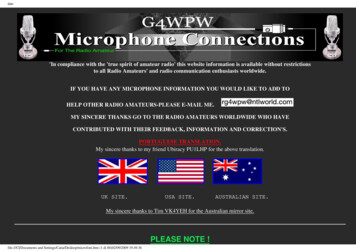
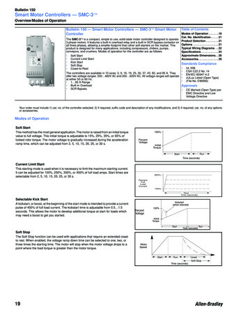
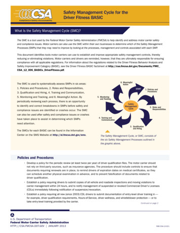
Chapter 1InstallationMounting RequirementsAll units are fan cooled. It is important to locate the controller in a positionthat allows air to flow vertically through the power module.IMPORTANTThe controller must be mounted in a vertical plane and have a minimum of 6 in.(150 mm) free space above and below the controller. Horizontal mounting of theSMC-50 controller is not allowed. Enclosure must be sized such that the enclosure’sinternal temperature remains within specified controller ratings.See Table 2 for minimum enclosure dimensions.When you drill or install near the soft starter, make sure that you take adequatemeasures to protect the device from dust and debris, as shown in Figure 1.Figure 1 - SMC-50 Controller Mounting Protection8Rockwell Automation Publication 150-QS003E-EN-P - April 2017
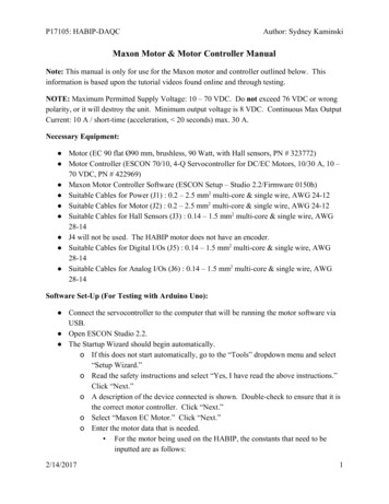
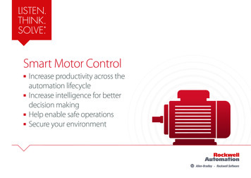
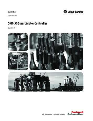
InstallationDimensionsChapter 1Dimensions are in millimeters (inches). All dimensions are approximate andare not intended for manufacturing purposes. For complete dimensiondrawings, see the user manual, publication 150-UM011, or consult your localRockwell Automation sales office or Allen-Bradley distributor.Figure 2 - SMC-50 Soft Starter with Integral BypassABCat. No.Height (B)Width (A)Depth (C)150-S108 / 150-S135 150-S201 / 150-S251 150-S317 / 150-S361 / 150-S480 443.7 (17.47)560.0 (22.05)600.0 (23.62)196.4 (7.74)225.0 (8.86)290.0 (11.42)217.3 (8.56)277.4 (10.92)310.1 (12.21)Rockwell Automation Publication 150-QS003E-EN-P - April 2017Approximate ShippingWeight15.4 kg (34.0 lb)30.8 kg (68.0 lb)46.2 kg (102 lb)9
Chapter 1InstallationFigure 3 - Solid-state SMC-50 Soft StarterABCat. No.150-SB 150-SC 150-SD Power WiringHeight (B)396.6 (15.62)638.5 (25.14)692.2 (27.25)Width (A)194.4 (7.65)273.1 (10.75)457.2 (18.00)Depth (C)259.2 (10.21)272.9 (10.75)295.8 (11.64)Approximate Shipping Weight15.7 kg (34.6 lb)47.6 kg (105 lb)77.1 kg (170 lb)See the product nameplate or the SMC-50 controller user manual, publication150-UM011, for device-specific information.SMC-50 controller power structures use solid-state SCR designs that arecapable of interfacing with 200.480V AC or 200.690V AC (690V line and600V inside-the-delta) motors. Both the internally bypassed and solid-statepower structures are available. Verify ratings of unit before application.The power structure incorporates three-phase true current-sensing andovertemperature protection. You can use an external bypass contactor if it isrequired for your application.Conductor range, torque, lug, and delta distribution block lug kit informationis provided in Table 3 through Table 6. Figure 4 supplies typical power wiringdiagrams.ATTENTION: SMC-50 controllers can be installed in a system with powerfactor correction capacitors (PFCCs). The PFCCs must only be on the line sideof the controller. Placing the PFCCs on the load side of the SMC results indamage to the SCRs in the SMC-50 controller. For additional details, see theuser manual, publication 150-UM011.10Rockwell Automation Publication 150-QS003E-EN-P - April 2017
InstallationPower LugsChapter 1Power lugs are required for devices rated 108 480 A (internal bypass) and90 520 A (solid-state). These lugs are sold in kits. Each kit contains three lugs.Table 3 through Table 6 list the number and type of lugs required.Table 3 - SMC-50 Integrated Bypass Devices Connection Lug Information for Line/WyeConnected MotorsCat. No.Lug KitRating [A] Cat.No.Wire StripLength [mm]150-S108 , 150-S135 108 135199-LF118 20150-S201 , 150-S251 201 251199-LF118 20150-S317 , 150-S361 , 150-S480 317 480199-LG118 25Conductor Range16 120 mm2(#6 250 MCM)16 120 mm2(#6 250 MCM)25 240 mm2(#4 500 MCM)Max No. Lugs/PoleLine Side Load Side112222Tightening TorqueWire - LugLug - Busbar31 N m17 N m(275 lb in)(150 lb in)31 N m23 N m(275 lb in)(200 lb in)42 N m28 N m(375 lb in)(250 lb in)Table 4 - SMC-50 Integrated Bypass Devices Connection Lug Information for Inside-the-DeltaConnected MotorsRating [A]Lug KitCat. No.150-S108 , 150-S135 187 2341494R-N15150-S201 , 150-S251 348 4351494R-N14150-S317 , 150-S361 , 150-S480 549 831150-LG5MCCat. No.Conductor RangeMax No. Lugs/PoleLine Side25 240 mm2(#4 500 MCM)50 120 mm2(1/0 250 MCM)95 240 mm2(3/0 500 MCM)121Tightening TorqueWire - LugLug - Busbar42 N m17 N m(375 lb in)(150 lb in)31 N m23 N m(275 lb in)(200 lb in)34 N m28 N m(300 lb in)(250 lb in)Table 5 - Solid-state SMC-50 Controller Power Wiring Information, Line/Wye andInside-the-Delta ConfigurationsCat. No.Rating [A]Lug KitCat. No.Wire StripLength [mm]150-SB 90 180 (Line/Wye)155 311 (Delta)210 320 (Line/Wye)363 554 (Delta)361 520 (Line/Wye)625 900 (Delta)199-LF118 20199-LF118 20199-LG118 25150-SC 150-SD Conductor Range16 120 mm2(#6 250 MCM)16 120 mm2(#6 250 MCM)25 240 mm2(#4 500 MCM)Max No. Lugs/PoleLine Side Load Side112222Tightening TorqueWire - LugLug - Busbar31 N m23 N m(275 lb in)(200 lb in)31 N m23 N m(275 lb in)(200 lb in)42 N m28 N m(375 lb in)(250 lb in)Table 6 - Solid-state SMC-50 Controller Delta Distribution Block Wiring InformationCat. No.150-SB 150-SC 150-SD Tightening TorqueLineLoad42 N m(375 lb in.)67.8 N m31 N m(600 lb in.)(275 lb in.)67.8 N m67.8 N m(600 lb in.)(600 lb in.)Quantity313Conductor RangeLineLoad225 240 mm(#4 500 MCM)54 400 mm216 120 mm2(1/0 750 MCM) (#6 250 MCM)54 400 mm254 400 mm2(1/0 750 MCM) (1/0 750 MCM)Wire Strip Length [mm]LineLoadRockwell Automation Publication 150-QS003E-EN-P - April 2017353545Top Row 23Bottom Row 484545Lug Kit Cat. No.Allen-Bradley1492-BGMarathon SpecialProducts 1353703Marathon SpecialProducts 135270211
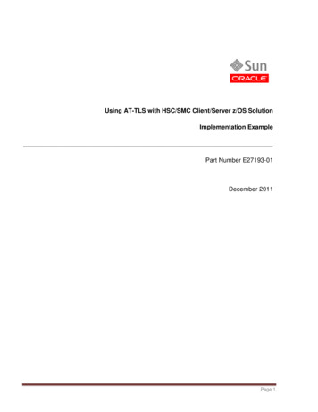
Chapter 1InstallationTypical Power DiagramsFigure 4 - Power Wiring DiagramsDiagrams per NEMA SymbologyLine connection withisolation contactor(default mode)Inside-the-Delta connectionwith isolation contactor(optional mode)Delta connection withshorted SCR protection(optional mode)SMC-50 controllerwith internal bypassL1 L2 L3L1(1)K1L2L1 L2L3L3(1)K1T5SMC-50 solid-statecontrollerT6SMC-50controllerT1 T2T4T3T1K1SMC-50controllerSMC-50controllerT1T2 T3Motor(2)T6 T4 T5T2 T3MotorMotorDiagrams per IEC SymbologyLine connection withisolation contactor(default mode)L1 L2SMC-50 controllerwith internal bypassL1 L2L3L3Delta connection withshorted SCR protection(optional mode)L1 L2L3135135135214365214365246246135K1SMC-50 solid-statecontrollerInside-the-Delta connectionwith isolation contactor(optional roller246UVW3 MotorW2U22U14V16W13 MotorSMC-50controller2U14V1135K1(2)26W1W24U26V23 Motor(1) Contactor must be fully rated for motor Hp/kW and FLA.(2) For North American applications, size the contactor per the motor Hp and FLA. For IEC applications, size the contactor per themotor AC-1 or AC-3 rating. The short-circuit rating of the contactor must be similar to that of the SMC-50.12Rockwell Automation Publication 150-QS003E-EN-P - April 2017
InstallationControl WiringChapter 1Standard Control Terminal BlockSMC-50 controllers come standard with two 24V DC digital on/off inputsand two relay outputs for auxiliary control functions. The standard digital I/Owiring terminal block is on the upper right portion of the SMC-50 controller.The terminal block is removable.Control Wiring SpecificationsThe following table provides the specifications for all SMC-50 controllercontrol wiring and option module terminal blocks. Each wiring terminalaccepts a maximum of two wires.Table 7 - Control Wiring SpecificationsWire Size0.2.2.5 mm2 (#24.14 AWG)Maximum Torque0.8 N m (7 lb in.)Maximum Wire Strip Length7 mm (0.27 in.)Screw TypeM3 SlottedSHOCK HAZARD: To prevent the risk of electrical shock, disconnect all powersources from the controller and option module before you install or service it.Install the controller and option module in a suitable enclosure and keep itfree of contaminants.Rockwell Automation Publication 150-QS003E-EN-P - April 201713
Chapter 1InstallationFigure 5 - Standard Control Terminal Block Identification24V DC Inputs867Internal DC CommonIn2 DC9Enable I/O1011In1 DCInternal 24V DC12Aux 245321-L2 L1Aux 1Relay OutputsControl Powerand Ground (1)(1) See the controller nameplate to verify the control power ratings (120/240V AC or 24V DC).ATTENTION: IN1 DC (terminal 11) and IN2 DC (terminal 10) are 24V DCinputs on controllers rated 120/240V AC and on controllers rated 24V DC.Voltages that exceed the specified input range may cause damage to thecontroller.Terminal NumberDescription1 (1) (2)Control Power L12(1)(2)Control Power Common -L23Ground — To connect to the system/control ground point.4 (1)(3)Auxiliary Relay Contact #1—rated 3 A @ 120V AC, 1.5 A @ 240V AC5 (1)(3)Auxiliary Relay Contact #1—rated 3 A @ 120V AC, 1.5 A @ 240V AC6 (1)(3)Auxiliary Relay Contact #2—rated 3 A @ 120V AC, 1.5 A @ 240V AC7 (1)(3)Auxiliary Relay Contact #2—rated 3 A @ 120V AC, 1.5 A @ 240V AC8DC Internal I/O Power, DC Common9Enable I/O10 (1)(4)Input #2 (24V DC) (range 15 30V DC)11 (1)(4)Input #1 (24V DC) (range 15 30V DC)12 24V DC Internal I/O Power(1) RC snubbers are required when inductive loads are connected to terminal.(2) See the controller nameplate to verify the control power ratings (120/240V AC or 24V DC)(3) When set to external bypass mode, the auxiliary contact is used to control a properly sized external contactor and overload oncethe motor is at full speed.(4) Do not connect any additional loads to this terminal. Parasitic loads may cause problems with operation.14Rockwell Automation Publication 150-QS003E-EN-P - April 2017
InstallationChapter 1Typical Control Wiring ExamplesFigure 6 and Figure 7 are control wiring diagram examples using the controllerstandard I/O. For additional wiring examples, see the SMC-50 controller usermanual, publication 150-UM011.Figure 6 - Two-wire Control (No DPI) with Fault IndicationIndication LED-L2 L1Start/Stop (3)Control PowerControlGround(1)(6)(1)(4)8Intl DC Common9Enable I/O10In2 DC11In1 DCIntl 24V DC12-L2 L1(2)(5)67Aux 245321-L2 L1Aux 1(1) Customer supplied.(2) See the controller nameplate to verify the control power input ratings (120V/240V AC or 24V DC).(3) Terminal 10 (IN2) 24V DC normally open (N.O.) input is configured for Start/Stop or Start/Coast usingParameter 57. When using the Start/Stop or Start/Coast, the N.O. contact must be used.NOTE: The controller generates an I/O configuration fault if any input is configured for START or SLOW speed and no input isconfigured for COAST or STOP.(4) A customer-supplied jumper is required to enable the controller’s standard I/O operation.(5) The terminal must be wired to the control ground to maintain reliable operation.(6) The Aux2 output contact is configured for Fault using Parameter 176.NOTE: Due to current leakage through an SCR in the OFF state (controller stopped), some form of upstream line power isolation isrecommended if maintenance is required on the motor. See the typical wiring diagram for Isolation Contactor Application in theuser manual.TIPWhen you are using two-wire control with IN1 and/or IN2 set for eitherStart/Stop or Start/Coast, you cannot start the SMC-50 controller via a HIM.If you want to start and stop the motor in test mode via a HIM, use thefollowing steps: Set IN1 (Parameter 56) and IN2 (Parameter 57) to “Disable”. Clear the I/O Config Fault, if it appears. Set the Logic Mask (Parameter 148) to the appropriate bit, based onwhich device port the HIM is using.Motor should now start and coast via HIM commands.Rockwell Automation Publication 150-QS003E-EN-P - April 201715
Chapter 1InstallationF
The SMC-50 soft starter is a reduced voltage soft starter that uses a state-of- the-art microprocessor- based control module. By using six back-to-back silicon-controlled rectifiers (SCRs) (two per phase), the SMC-50 soft starter provides controlled acceleration, operation/run, and deceleration of standard asynchronous induction motors.