Transcription
QUICK STARTSMC FLEXBULLETIN 150This guide provides you with the basic information required to start up your SMC Flex controller. When readingthis document, look for this symbol “Step x” to guide you through the four basic steps required to install, start-up,and program the SMC Flex.The information provided in this Quick Start guide does not replace the User Manual which can be ordered ordownloaded by visiting www.ab.com. The Quick Start guide assumes the installer is a qualified person withprevious experience and basic understanding of electrical terminology, configuration procedures, requiredequipment, and safety precautions.For safety of maintenance personnel as well as others who might be exposed to electrical hazards associated withmaintenance activities, follow all local safety related work practices (for example, the NFPA 70E, Part II in theUnited States). Maintenance personnel must be trained in the safety practices, procedures, and requirements thatpertain to their respective job assignments.For detailed SMC Flex information including set-up, programming, precautions, and application considerations,refer to the following documentation.TitlePublication NumberAvailabilitySMC Flex User Manual150-UM008*www.ab.com/literatureSMC Flex Application Guide150-AT002*www.ab.com/literatureFor product technical support:Online Supportwww.ab.com/supportTelephone Support440-646-5800 (option 2, option 4 or usedirect dial code 804)
2SMC Flex Quick StartStep 1 - Read the General Precautions!WARNING Only personnel familiar with the controller and associated machinery should plan or implement theinstallation, start-up, and subsequent maintenance of the system. Failure to do this may result in personal injuryand/or equipment damage. Hazardous voltage is present in the motor circuit even when the SMC-Flex controller is off. To avoid shockhazard, disconnect main power before working on the controller, motor, and control devices such as Start-Stoppush buttons. Procedures that require parts of the equipment to be energized during troubleshooting, testing,etc., must be performed by properly qualified personnel, using appropriate local safety work practices andprecautionary measures. Failure of solid state power switching components can cause overheating due to a single-phase condition in themotor. To prevent injury or equipment damage, the use of an isolation contactor or shunt trip type circuitbreaker on the line side of the SMC is recommended. This device should be capable of interrupting the motor’slock rotor current. Hazardous voltages that can cause shock, burn, or death are present on L1, L2, L3, T1, T2, T3, T4, T5, and T6.Power terminal covers for units rated 108 480 A can be installed to prevent inadvertent contact withterminals. Disconnect the main power before servicing the motor controller, motor, or associated wiring.
SMC Flex Quick Start3NOTICE The controller contains ESD- (electrostatic discharge) sensitive parts and assemblies. Static control precautionsare required when installing, testing, servicing, or repairing the assembly. Component damage may result ifESD control procedures are not followed. If you are not familiar with static control procedures, refer toapplicable ESD protection handbooks. Stopping modes are not intended to be used as an emergency stop. The user is responsible for determiningwhich stopping mode is best suited to the application. Refer to the applicable standards for emergency stoprequirements. Pump Stopping may cause motor heating depending on the mechanical dynamics of the pumping system.Therefore, select the lowest stopping time setting that will satisfactorily stop the pump. Slow Speed running is not intended for continuous operation due to reduced motor cooling. The fan jumpers have been factory installed for 110/120V AC input. Refer to page 9 for 220/240V AC fanwiring (5 480 A devices only). Two peripheral devices can be connected to the DPI port. The maximum output current through the DPI port is280 mA. When installing or inspecting protective modules, make sure that the controller has been disconnected from thepower source. The protective module should be inspected periodically for damage or discoloration. Replace ifnecessary. An incorrectly applied or installed controller can damage components or reduce product life. Wiring orapplication errors such as under sizing the motor, over sizing the controller, incorrect or inadequate AC supply,excessive ambient temperatures, or power quality may result in malfunction of the system. The Motor Overload parameter must be programmed by the installer to provide proper protection. Overloadconfiguration must be properly coordinated with the motor. This product has been designed and tested as Class A equipment for EMC compatibility. Use of the product indomestic environments may cause radio interference, in which case, the installer may need to employadditional mitigation methods. Disconnect the controller from the motor before measuring insulation resistance (IR) of the motor windings.Voltages used for insulation resistance testing can cause SCR failure. Do not make any measurements on thecontroller with an Insulation Resistance (IR or Megger) tester.
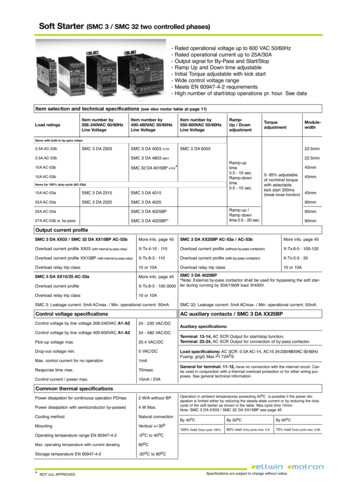
4SMC Flex Quick StartStep 2 - InstallationMountingEnclosure RatingsStandard Device RatingIP00 (NEMA Open Type)Minimum Required EnclosureIP23 (NEMA Type 1)Recommended EnclosureIP54 (NEMA Type 12), sizing guide in User ManualEnclosure Internal Temperature-5 50 C (23 122 F)Orientation and ClearanceMounting OrientationVerticalMinimum horizontal clearance0 cm (0 in.)Minimum vertical clearance15 cm (6 in.)Controllers rated 625 1250 ADevice must be lifted only at the designated lift points identified with labels.Lifting Points
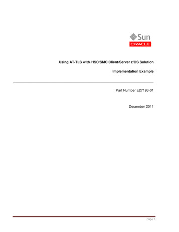
SMC Flex Quick StartDimensionsFor detailed dimensions, please refer to the SMC Flex User Manual.ACBLangEscSelSMC-Flex TM23 24 25 26 27 28 29 30 31 32 33 3411 12 13 14 15 16 17 18 19 20 21 22Dimensions are in millimeters (inches).Controller Rating [A]Height (B)Width (A)Depth (C)Approximate ShippingWeight5 85321.0 (12.60)150.0 (5.90)203.0 (8.00)5.7 kg (12.5 lb)108 135443.7 (17.47)196.4 (7.74)212.2 (8.35)15.0 kg (33.0 lb)201 251560.0 (22.05)225.0 (8.86)253.8 (9.99)30.4 kg (67.0 lb)317 480600.0 (23.62)290.0 (11.42)276.5 (10.89)45.8 kg (101 lb)625 7801041.1 (41.00)596.9 (23.50)346.2 (13.63)179 kg (395 lb)970 12501041.1 (41.00)596.9 (23.50)346.2 (13.63)224 kg (495 lb)5
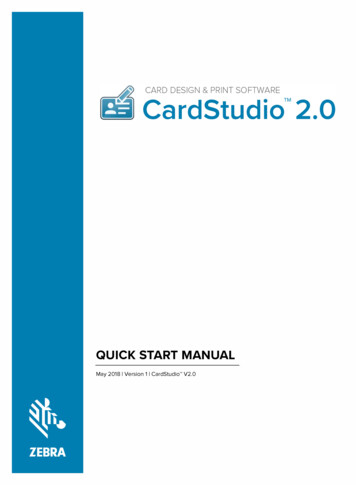
6SMC Flex Quick StartPower WiringRefer to the product nameplate or the SMC Flex User Manual for device specific information.SMC Rating[A]Lug KitCat. No.Wire StripLengthConductorRange5 85—18 20 mm2.5 85 mm2(#14 3/0 AWG)——108 135199-LF118 20 mm16 120 mm2(#6 250 MCM)1131 N m(275 lb in)23 N m(200 lb in)201 251199-LF118 20 mm16 120 mm2(#6 250 MCM)2231 N m(275 lb in)23 N m(200 lb in)317 480199-LG118 25 mm25 240 mm2(#4 500 MCM)2242 N m(375 lb in)28 N m(250 lb in)625 780100-DL63032 mm/64 mm70 240 mm2(2/0 500 MCM)2245 N m(400 lb in)68 N m(600 lb in)970100-DL86026 mm/48 mm120 240 mm2(4/0 500 MCM)1145 N m(400 lb in)68 N m(600 lb in)100-DL63032 mm/64 mm70 240 mm2(2/0 500 MCM)111145 N m(400 lb in)68 N m(600 lb in)1250100-DL86026 mm/48 mmMax. No. Lugs/PoleLine SideLoad Side2120 240 mm(4/0 500 MCM)Tightening TorqueWire - LugLug - Busbar11.3 N m—(100 lb in)Control Terminals23 24 2526 27 2829 30 3132 33 3411 12 1314 15 1617 18 1920 21 rol Power Input ( )Control Power CommonController Enable InputGroundOption In r units rated 690VAC230 690VN/AN/AN/AN/AN/AN/AN/A150-FPP108Z ➁150-FPP135Z ➁150-FPP201Z ➂150-FPP251Z ➂150-FPP317Z ➂150-FPP361Z ➂150-FPP480Z ➂150-FPP625Z ➂150-FPP780Z ➂150-FPP970Z ➂150-FPP1250Z ➂
Publication 150-QS001G-EN-P — August 2008Superecedes Publication 150-QS001F-EN-P — November 200640055-217-01 (7)Copyright 2008 Rockwell Automation, Inc. All Rights Reserved. Printed in USA.
This guide provides you with the basic information required to start up your SMC Flex controller. When reading this document, look for this symbol "Step x" to guide you through the four basic steps required to install, start-up, and program the SMC Flex.