Transcription
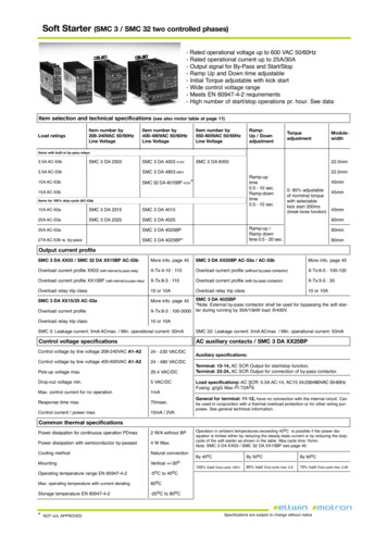
Soft Starter (SMC 3 / SMC 32 two controlled phases)& '!(#) * # !(,*-!. /*.(!"# 0 (* 122 345 6271289& '!(#) * # !(,*-!. :0 #-( 0 (* ;647 24 & 0( 0( ,"-!. ?* @A&B! !-) C(! (7C(*& '!D E !-) F*G- (,D# !)H0 (!I.# & J-,(,!. K* L0# !)H0 (!I.# G,(M N,:N (! (& O,)# :*-( *. /*.(!"# !-"#& P##( QR 12STU&T&; #L0, #D#-( & 8,"M -0DI# *? (! (7 (* * # !(,*- V M*0 V C## )!(!Item selection and technical specifications (see also motor table at page 11)Load ratingsItem number by208-240VAC 50/60HzLine VoltageItem number by400-480VAC 50/60HzLine VoltageItem number by550-600VAC 50/60HzLine VoltageCP5 F4 T22 TW63CP5 F4 122 RampUp / DownadjustmentTorqueadjustmentModulewidthItems with built-in by-pass relays V64 45&6 ICP5 F4 ; 2 ;;V6DDCP5 F4 T%2 T%23 V64 45&6 I;;V6DD'!D &0(,D# 2V6 & W2 #:V'!D &)*G- (,D#2V6 & W2 #:VCP5 ; F4 T2W6@B TW63XW64 45&6 IW64 45&6 IItems for 100% duty-cycle (AC-53a)W64 45&6 !CP5 F4 ; W6;64 45&6 !CP5 F4 ; ;6CP5 F4 T2W6T6DD2& %6Y !)H0 (!I.# *? -* D,-!. (* L0#G,(M #.#:(!I.# N,:N (! ( ;22D ZI #!N .** # ?0-:(,*-[CP5 F4 T2;6;64 45&6 !CP5 F4 T2;6@B;U4 45&6 I GV IA& ! CP5 F4 T2;6@BXT6DDT6DDS2DD'!D &0 7'!D )*G- (,D# 2V6 & ;2 #:VS2DDS2DDOutput current profileSMC 3 DA XX03 / SMC 32 DA XX15BP AC-53bP* # ,-?*V !"# T6SMC 3 DA XX25BP AC-53a / AC-53bP* # ,-?*V !"# T6 /# .*!) :0 #-( *?,.# \\2 ZG,(M ,-(# -!. IA&\&K] T&W2 WW2 /# .*!) :0 #-( *?,.# ZG,(M*0( IA& ! :*-(!:(* [\&K] 1&6 W22&W;2\&K] %& WW2 /# .*!) :0 #-( *?,.# ZG,(M IA& ! :*-(!:(* [\&K] 6&6 2 /# .*!) #.!A ( , :.! W2 * W24 /# .*!) #.!A ( , :.! W2 * W24SMC 3 DA XX15/25 AC-53a /# .*!) :0 #-( *?,.# P* # ,-?*V !"# T6 SMC 3 DA 4025BP*R*(# Q](# -!. IA& ! :*-(!:(* M!. I# 0 #) ?* IA ! ,-" (M# *?( (! &\&K] %& W22& 222 (# )0 ,-" 0--,-" IA 247W6NO .*!) cT223V /# .*!) #.!A ( , :.! W2 * W24! #.!A[ /# .*!) :0 #-( *?,.# \\W6@B ZG,(M ,-(# -!. IA&! #.!A[CP5 d#!N!"# :0 #-( 6D4 45D!]V 7 P,-V * # !(,*-!. :0 #-( 62D4CP5 ; d#!N!"# :0 #-( 6D4 45D!]V 7 P,-V * # !(,*-!. :0 #-( 62D4Control voltage specificationsAC auxiliary contacts / SMC 3 DA XX25BP5*-( *. /*.(!"# IA .,-# /*.(!"# ;2%&;T2345 A1-A2;T & ; 2 3457F55*-( *. /*.(!"# IA .,-# /*.(!"# T22&122345 A1-A2;T & T%2 3457F5B,:N&0 /*.(!"# D!]V;2VT 3457F5F * &*0( /*.(!"# D,-V6 3457F5P!]V :*-( *. :0 #-( ?* -* * # !(,*-WD4'# *- # (,D# D!]VU2D #:V5*-( *. :0 #-( 7 *G# D!]VW6D4 7 ;34Auxiliary specifications:Terminal: 13-14, 45 C5' 0( 0( ?* (! (7 (* ?0-:(,*- Terminal: 23-24, 45 C5' 0( 0( ?* :*--#:(,*- *? IA& ! :*-(!:(* VLoad specifications: 45 C5' 2V64 45&WT 45W6 ;T&; 27T%2345 62&1289 a0 ,-" ".7"b P!] ,;( U;4;CGeneral for terminal: 11-12, M!/# -* :*--#:(,*- G,(M (M# ,-(# -!. :, :0,(V 5!- I# 0 #) ,- :*-H0-:(,*- G,(M ! (M# D!. */# .*!) *(#:(,*- * ?* *(M# G, ,-" 0 &* # V C## "#-# !. (#:M-,:!. ,-?* D!(,*-VCommon thermal specificationsB*G# ), , !(,*- ?* :*-(,-0*0 * # !(,*- BFD!]; O74 G,(M*0( @BB*G# ), , !(,*- G,(M #D,:*-)0:(* IA& ! #)T O P!]V 5**.,-" D#(M*)R!(0 !. :*-/#:(,*-P*0-(,-" 3# (,:!. 7& 2* # !(,-" (#D # !(0 # !-"# QR 12STU&T&;&6*5 (* T2*5 P!]V * # !(,-" (#D # !(0 # G,(M :0 #-( )# !(,-" 12*5 C(* !"# (#D # !(0 # QR 12STU&T&;&;2*5 (* %2*5 X R K :Ed 4BB' 3QF # !(,*- ,- !DI,#-( (#D # !(0 # #]:##),-" T2*5 , * ,I.# ,? (M# *G# ), & , !(,*- , .,D,(#) #,(M# IA #)0:,-" (M# (#!)A& (!(# :0 #-( * IA #)0:,-" (M# )0(A&:A:.# *? (M# *?( (! (# ! M*G- ,- (M# (!I.#V P!]V:A:.# (,D# W6D,-V R*(# CP5 F4 \\2 7 CP5 ; F4 \\W6@B ## !"# T6V@A T2*5 @A 62*5@A 12*5W22Y .*!) F0(A&:A:.# W22Y%2Y .*!) F0(A&:A:.# D!]V 2V%U2Y .*!) F0(A&:A:.# D!]V 2V16C #:,?,:!(,*- ! # 0IH#:( (* :M!-"# G,(M*0( -*(,:#
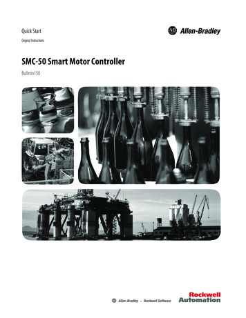
Soft Starter (SMC 3 / SMC 32 two controlled phases)Wiring specificationsSMC 3 DA XX03SMC 32 DA XX15BPSMC 3 DA XX25 BPSMC 3 DA XX15/25WW&W; ?* EB1; * *(M# G, ,-" 0 * # WW&W; ?* EB1; * *(M# G, ,-" 0 * # 5*-( *. /*.(!"# 4W&4;5*-( *. /*.(!"# 4W&4;Wiring example Start/Stop-By-pass (SMC 3 DA XX25 BP)40],.,! A C5' *0( 0( :*-(!:( W & WT Z45 /*.(!"# *-.A[ , 0 #) ?* :*-&( *.,-" ! C(! (&C(* ?0-:(,*- ), #:(.A G, #) (* (M# *?( (! (# V 40],.,! A C'5 *0( 0( :*-(!:( ; &;T Z45 /*.(!"# *-.A[ , !:(,/!(#) GM#- (M# !D &0 (,D# M! #.! #)V J 0 #) ?* IA& ! ,-" (M# *?( (! (# G,(M !- #](# -!. :*--#:(#) #.#:( *D#:M!-,:!. :*-(!:(* V 0( 0( W &WT a* :*-( *. *? C(! (7C(* ?0-:(,*- 0( 0( ; &;T @A #-) *? !D 0 (,D# ?* IA& ! :*-(!:(* Motor wiring with or without by-pass (SMC 3 DA XX25 BP)C(!-)! ) G, ,-" *? ! *?( (! (# (* ! & M! # D*(* ,- )#.(! :*-&?,"0 !(,*-VC(*C(! (J-&.,-# G, ,-"XE # Ed ! */#) P!"-#(,: 5, :0,( @ #!N# * Ed #:,?,#) I!:N&0 ?0 # (A # e6 * 8 5.! O,(M * G,(M*0(IA& ! :*-(!:(* Short-circuit protection by circuit breaker or fusesTwo type of short-circuit protection can be used:![ CM* (&:, :0,( *(#:(,*- IA :, :0,( I #!N# VI[ CM* (&:, :0,( *(#:(,*- IA ?0 # VCM* (&:, :0,( *(#:(,*- , ),/,)#) ,-(* ; .#/#. Type 1 or Type 2b) Short-circuit protection by fusesKAKAKAKAKA# W CP5 F4 \\2 # W CP5 ; F4 \\W6 @B # W CP5 F4 \\W6 # W CP5 F4 \\;6 # W CP5 F4 \\;6 @B KAKAKAKAKA# ; CP5 F4 \\2 # ; CP5 ; F4 \\W6 @B # ; CP5 F4 \\W6 # ; CP5 F4 \\;6 # ; CP5 F4 \\;6 @B B *(#:(,*- D!]V ;6 4V "d7"b B *(#:(,*- D!]V 62 4V "d7"b 1 4 K B *(#:(,*- D!]V 62 4V "d7"b 1 4 K B *(#:(,*- D!]V %2 4V "d7"b 1 4 K B *(#:(,*- D!]V %2 4V "d7"b 1 4 K Co-ordination Type 1: CM* (&:, :0,( *(#:( (M# ,- (!.!(,*Co-ordination Type 2: CM* (&:, :0,( *(#:( (M# ,- (!.!(,*- !-) (M# #D,&:*-)0:(* ,- ,)# (M# D*(* :*-( *.# a) Short-circuit protection5*&* ),-!(,*- (A # W G,. I# *I(!,-#) GM#- 0 ,-" D!"-#(,: :, :0,( I #!N# * (!-)! ) ".7b. ?0 # V5*&* ),-!(,*- (A # ; G,. I# *I(!,-#) GM#- 0 ,-" #D,:*-)0:(* ?0 # VOM#- 0 ,-" #D,:*-)0:(* ?0 # (M# C5' G,. -*( I# )!D!"#) )0# (* ( !- ,#-( !-) M* ( :, :0,( V KM# (!I.# ,-),:!(# 0,(!I.# ?0 # ?* :*&* ),-!(,*- (A # ; *(#:(,*-V */#) CP5 ; F4 \\W6@B[Application, adjustment hints and general specificationsC## !"# W2&WW 7 TT&T6B *(#:(,*- D!]V ,;( *? (M# ?0 # U; 4;CB *(#:(,*- D!]V ,;( *? (M# ?0 # W%22 4;C B *(#:(,*- D!]V ,;( *? (M# ?0 # W%22 4;C B *(#:(,*- D!]V ,;( *? (M# ?0 # 1 22 4;CB *(#:(,*- D!]V ,;( *? (M# ?0 # 1 22 4;CFuses from e.g. Ferraz, Siba, Bussmann canbe used as short-circuit protection Type 2P* # ,-?* D!(,*- :*-:# -,-" 5*&* ),-!(,*- KA # ; ## !"# T6Dimensions Z ## !. * !"# TT[Approval:Ed C() R*V 62% ZR*( ! KA #8 FO;;V6 DD D*)0.#ST DDW; V% DD;;V6 DDT6 DD D*)0.#ST DDW;%VW DDT6 DDS2 DD D*)0.#ST DDW;%VW DDS2 DD
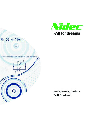
Soft Starter (SMC 33 / three controlled phases)- Rated operational voltage up to 480 VAC 50/60Hz- Rated operational current up to 86A (inside delta DBP)- Output signal for By-Pass and Start/Stop- Ramp Up and Down time adjustable- Initial Torque adjustable with kick start- Wide control voltage range- Meets EN 60947-4-2 requirements- High number of start/stop operations pr. hour. See data.Item selection and technical specifications (see also motor table at page 11)Load ratings1Inside delta configuration****Item number by208-240VAC 50/60HzLine VoltageItem number by400-480VAC 50/60HzLine VoltageItem number by550-600VAC 50/60HzLine VoltageRampUp / DownadjustmentTorqueadjustmentModulewidth15A AC-53aSMC 33 DA 401590 mm15A AC-53a no by-passSMC 33 DA 4025BP90 mm27A AC-53b w. by-passSMC 33 DA 4025BP35A AC-53a no by-pass50A AC-53b w. by-pass*SMC 33 DA 2350BP*SMC 33 DA 2350BPRamp-uptime0.5 - 30 sec.*SMC 33 DA 4050BP*SMC 33 DA 4050BPRamp-downtime0.5 - 60 sec.Items for Inside delta configuration125A AC-53a no by-passSMC 33 DA 4040DBP143A AC-53b w. by-passSMC 33 DA 4040DBP160A AC-53a no by-pass186A AC-53b w. by-pass90 mm0- 85% adjustableof norminal torquewith selectablekick start 200ms180 mm(break loose function)90 mm90 mm*SMC 33 DA 2385DBP* SMC 33 DA 4085DBP*SMC 33 DA 2385DBP*180 mm180 mmSMC 33 DA 4085DBP180 mmLoad specified with utilisation category AC-53aLoad specified with utilisation category AC53bSMC 33 DA XXXX BP AC-53a: No by-pass contactors is nessesary duringrunning, shall be connected as inline confirgurationSMC 33 DA XXXX BP AC-53b: By-pass contactor shall be used for bypassing the soft starter during running, shall be connected as inline confirgurationSMC 33 DA XXXX DBP AC-53a: No by-pass contactors is nessesary butmotor shall be connected in an inside-delta confirgurationSMC 33 DA XXXX DBP AC-53b: By-pass contactor shall be used andmotor connected in an inside-delta configurationOutput load specification (90mm module)Output load specification (180mm module)more info page 45more info page 45Overload current profile AC-53a (without by-pass contactor)X-Tx:6-5 : 100-120Overload current profile AC-53a (without by-pass contactor)X-Tx:6-6 : 100-120Overload current profile AC-53b (with by-pass contactor)X-Tx:5-5 : 30Overload current profile AC-53b (with by-pass contactor)X-Tx:6-6 : 30Overload relay trip class AC-53a/AC53b10 or 10AOverload relay trip class AC-53a/AC53b10 or 10ALeakage current: 5mA ACmax.Min. operational current: 50mALeakage current: 5mA ACmax.Min. operational current: 50mAAuxiliary contactsControl terminal specificationsControl voltage by line voltage 208-240VAC A1-A224 - 230 VAC/DCControl voltage by line voltage 400-600VAC A1-A224 - 480 VAC/DCPick-up voltage max.20.4 VAC/DCDrop-out voltage min.5 VAC/DCMax. control current for no operation1mAOutput specifications for 180mm module: AC SCR: 1.0A AC-14, AC1524-230/480V AC 50-60Hz Fusing: gl/gG Max i2t 72A2SResponse time max.70msec.Terminal: 11-12, have no connection with the internal circuit. Can be used inControl current / power max.15mA / 2VATerminal: 13-14, AC SCR output for start/stop function,Terminal: 23-24, AC SCR output for connection of by-pass contactor.Output specifications for 90mm module: AC SCR: 0.5A AC-14, AC1524-230/480V AC 50-60Hz Fusing: gl/gG Max i2t 72A2Sconjunction with a thermal overload protection or for other wiring purposes. Seeunder general technical information.Thermal specificationPower dissipation for continuous operation PDmax3 W/A without BPPower dissipation with semiconductor by-passed5 W Max. with BPCooling methodNatural convectionMountingVertical /-30oOperating temperature range EN 60947-4-2-5oC to 40oCMax. operating temperature with current derating60oCStorage temperature EN 60947-4-2-20oC to 80oC* NOT cUL APPROVEDOperation in ambient temperatures exceeding 40oC is possible if the powerdissipation is limited either by reducing the steady-state current or by reducingthe duty-cycle of the soft starter as shown in the table. Max.cycle time 15min.By 40oCBy 50oCBy 60oC100% load Duty-cycle 100%80% load Duty-cycle max. 0,870% load Duty-cycle max. 0,65Specifications are subject to change without notice
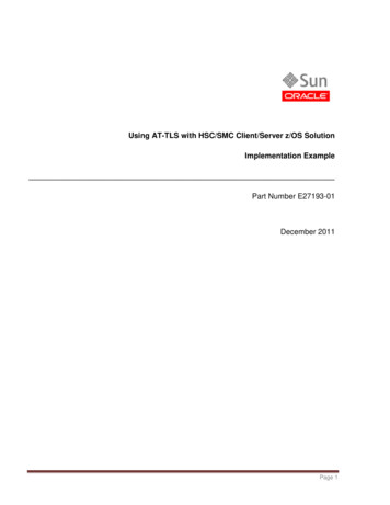
Soft Starter (SMC 33 / three controlled phases)Wiring specifications (90mm module)Wiring specifications (180mm module)11-12: for UP62 or other wiring purposesControl voltage A1-A2Output 13-14:For control of Start/Stop functionDo not includeSMC 33 DA XX15Output 23-24:By end of ramp up timefor by-pass contactorWiring information: Inside-delta configurationStandard wiring of a softstarterto a 3-phase motor in delta configuration.With or withoutby-pass contactorControl voltage A1-A2Output 23-24:By end of ramp up timefor by-pass contactorDo not includeSMC 33 DA XX15Wiring information: Delta configurationOutput 13-14:For control of Start/Stop function11-12: for UP62 or other wiring purposesInside-delta wiring of a softstarter toa 3- phase motor.*Use UL approvedMagnetic Circuit Breakeror UL specified back-upfuse type K5 or H ClassInside-deltawiring*Use UL approvedMagnetic Circuit Breakeror UL specified back-upfuse type K5 or H ClassWith or withoutby-passcontactorDelta wiringWiring example Start/Stop - By-pass (180 mm modul)Wiring example Start/Stop - By-pass (90 mm modul)Auxiliary SCR output contact 13-14 (AC voltage only) is used for controlling a Start-Stop function directly wired to the soft starter.Auxiliary SRC output contact 23-24 (AC voltage only) is activatedwhen the ramp-up time has elapsed. Is used for by-passing the softstarter with an external connected electromechanical contactor.StopStartAuxiliary SCR output contact 13-14 (AC voltage only) is used for controlling a Start-Stop function directly wired to the soft starter.Auxiliary SRC output contact 23-24 (AC voltage only) is activatedwhen the ramp-up time has elapsed. Is used for by-passing the softstarter with an external connected electromechanical contactor.StopStartShort-circuit protection by circuit breaker or fusesTwo type of short-circuit protection can be used:a) Short-circuit protection by circuit breaker.b) Short-circuit protection by fuses.Short-circuit protection is divided into 2 levels Type 1 or Type 2Co-ordination Type1: Short-circuit protects the installationCo-ordination Type 2: Short-circuit protects the installation and the semiconductors inside the motor controllera) Short-circuit protectionCo-ordination type 1 will be obtained when using magnetic circuit breakersor standard gl/Gl fuses.Co-ordination type 2 will be obtained when using semiconductor fuses.When using semiconductor fuses the SCR will not be damaged due totransients and short circuits. The table indicates suitable fuses for coordination type 2 protection.b) Short-circuit protection by fusesType 1: SMC 33 DA XX15Type 1: SMC 33 DA XX25 BPType 1: SMC 33 DA XX40 DBPType 1: SMC 33 DA XX50 BPType 1: SMC 33 DA XX85 DBPProtection max. 50 A gL/gGProtection max. 80 A gL/gGProtection max. 80 A gL/gGProtection max. 125 A gL/gGProtection max. 125 A gL/gGType 2: SMC 33 DA XX15Type 2: SMC 33 DA XX25 BPType 2: SMC 33 DA XX40 DBPType 2: SMC 33 DA XX50 BPType 2: SMC 33 DA XX85 DBPProtection max. i2tProtection max. i2tProtection max. i2tProtection max. i2tProtection max. i2tof the fuse 1800 A2Sof the fuse 6300 A2Sof the fuse 6300 A2Sof the fuse 25300 A2Sof the fuse 25300 A2SFuses from e.g. Ferraz, Siba, Bussmann canbe used as short-circuit protection Type 2More information concerning Co-ordination Type 2 see page 45ApprovalApplication, adjustment hints and general specificationscUL Std No. 508 (Not approved SMC 33 DA XX50BP andSMC 33 DA XX85DBP)See page 10-11 / 44-45
3-Phase electronic motor contactor (Direct On Line)- For Direct On Line start of 3 phase motors- Rated operational voltage up to 600 VAC 50/60 Hz- Rated operational current up to 15A AC-3- Versatile control circuit: 24-480VAC / 24-60VDC- Unlimited number of start/stop operations / hour- LED Status indication- Meets EN 60947-4-2 requirements- Requires only 45 mm DIN rail spaceItem selection and technical specificationsLoad ratingsAC-53 motor load stand.AC-4 motor loadinching / pluggingControl voltage15A AC-5324-60VDC / 24-480VACItem number by208-240VAC 50/60HzLine VoltageItem number by400-480VAC 50/60HzLine VoltageItem number by550-600VAC 50/60HzLine VoltageModule-widthSMC 3 DA 4015 DOL45mmOutput load specificationOperational current AC-5315AMin. operational current50mALeakage current5mA ACmax.Duty cycle100%24-60 VDC/24-480 VACControl current / power max.6mA / 1.5 VAPick-up voltage max.20.4 VAC / DCMax. control voltage510 VACDrop-out voltage min.5 VAC / DCResponse time max.1 cyclePower dissipation for continuous operation PDmax2.2 W/APower dissipation for intermittent operation PD2.2 W/A x dutycycleOperation in ambient temperatures exceeding 40oC is possible if the powerdissipation is limited either by reducing the steady-state current or by reducingthe duty-cycle of the soft starter as shown in the table.Cooling methodNatural convectionBy 40oCBy 50oCBy 60oCMountingVertical /-30o100% load Duty-cycle 100%80% load Duty-cycle max. 0.870% load Duty-cycle max. 0.65Operating temperature range EN 60947-4-2-5Co to 40oCEnvironmentStorage temperature EN 60947-4-2-20Co to 80oCDegree of protectionMax. operating temperature with current derating60oCControl terminal specificationsControl voltageThermal specificationInsulation specificationsRated insulation voltageUi 660 VoltRated impulse withstand voltageUimp. 4 kVoltInstallation catagoryIIIIP 20Pollution degree3*This products has been designed for class A equipment. Use of the product indomestic environments may cause radio interference, in which case the user maybe required to employ additional mitigation methods.*UL:Use thermal overload protection as required by the National Electric Code.When protected by a non-time delay K5 or H Class fuse, rated 266% of motorFLA, this device is rated for use on a circuit capable of delivering not more than5,000 rms. symmetrical amperes, 600 V maximum. Maximum surrounding temperature 40 C.Utilisation Categories EN60947-4-2ApprovalCategory AC - 53Starting, switching off motors during running.ULc Std No. 508 / CAN/CSA-C22.2Category AC - 4Starting, plugging, reversing the motor rapidly whilethe motor is running.Mounting and cable wiring informationMounting information see page 36 / Cable wiring see page 37CategoryAC - 52aControl of slipring motor statorsCategoryAC - 53aControl of squirrel cage motorCategory AC - 58aControl of hermetic refrigerant compressors withautomatic resetting of overload releasesEMCThis component meets the requirements of the product standardEN60947-4-2 and is CE marked according to this standard.Specifications are subject to change without noticeDimensions (se also page 36)TypeHDW45 mm module94 mm128.1 mm45 mm
3-Phase electronic motor contactor (Direct On Line)Wiring specificationsThermal overload protection (see also page 36)SMC 3 DA XX15 DOLFor UP62 or other wiring purposesOptional thermal overload protection ispossible by inserting a thermostat in aslot on the right hand side of the softstarter. Type number UP62Example 1Control voltage A1-A2The thermostat can be connected inseries with the control circuit of the softstarter.When the temperature of the heatsinkexceeds 90oC the soft starter will switchOff.Note:When the temperature has droppedapprox. 30oC the soft starter will auto-Short-circuit protection by circuit breaker or fusesTwo type of short-circuit protection can be used:a) Short-circuit protection by circuit breaker.b) Short-circuit protection by fuses.matically be switched on again.Short-circuit protection is divided into 2 levels Type 1 or Type 2The thermostat is connected in serieswith the control circuit of the maincontactor.When the temperature of the heatsinkexceeds 90oC the main contactor willCo-ordination Type 1: Short-circuit protects the installationCo-ordination Type 2: Short-circuit protects the installation and the semiconductors inside the motor controllera) Short-circuit protection by circuit breakerA 3-Phase motor with correctly installed and adjusted overload relay will notshort circuit totally to earth or between the 3 phases. Part of the winding willnormally limit the short circuit current to a value that will cause instantaneous magnetic tripping of the circuit breaker without damage to the electronic contactor. The magnetic trip response current is approx. 11 times themax. adjustable current.b) Short-circuit protection by fusesType 1: SMC 3 DA XX15 DOLProtection max. 50 A gL/gGType 2: SMC 3 DA XX15 DOLProtection max. I2t of the fuse 1800 A2SFuses from e.g. Ferraz, Siba, Bussmann canbe used as short-circuit protection Type 2More information concerning Co-ordination Type 2 see page 37Overload Protection in Motor Control ReversingOverload protection of the motor is easilyachieved by installing a manual thermalmagnetic circuit breaker on the supply*Magneticside of the motor.Circuit BreakerThe circuit breaker provides means forpadlocking and the necessary clearancefor use as a circuit isolator according toEN 60204-1.Adjust the current limit on the MCBaccording to the rated nominal current ofthe motor*Use UL approved Magnetic Circuit Breaker orUL specified back-up fuse type K5 or H ClassExample 2switch Off.A manual reset is necessary to restartthis circuit.SMC 3 DOL General application informationThe SMC 3 DOL has been developed for cranes and other harsh applications where inching, jogging and plugging is frequently used and where ahigh number of operating cycles are essential. In such applications the lifetimeof the equipment is normally limited by the short lifetime of the electromechanical contactor. Electromechanical contactors are not designed to switchoff motors in locked rotor- or overload conditions where the current is 6times the nominal operational current (AC-4). The servere arcing will burnthe contact elements resulting in unreliable contact function.The Semiconductor Contactor will close the contacts in the zero crossing of the mainsvoltage and switch-Off will always occur in the zero crossing of the motorcurrent in this way voltage kickback from the inductive motor windings isavoided. The lifetime, therefore, of the Semiconductoc Contactor will alwaysbe at least one decade longer than the electromechanical contactor.Comparison of lifetime in different utilization actorAC-52aControl of slip-ringmotors, starting,switching Off0.7 Mill. Cycles25 Mill. CyclesAC-53aControl of squirrelcage motors, starting,switching Off1.3 Mill. Cycles25 Mill. CyclesAC-4Control of squirrelcage motors, starting,plugging, inching0.06 Mill. Cycles5 Mill. SMC3DA.DOL
Soft Starter (SMC 3 / SMC 32 two controlled phases) Wiring specifications Wiring example Start/Stop-By-pass . Terminal: 13-14, AC SCR output for start/stop function, Terminal: 23-24, AC SCR output for connection of by-pass contactor. Output specifications for 90mm module: AC SCR: 0.5A AC-14, AC15