Transcription
FT230X USB TO BASIC UART ICVersion 1.1Document No.: FT 000566 Clearance No.: FTDI# 260Future TechnologyDevices InternationalLtd.FT230X(USB to BASIC UART IC)The FT230X is a USB to serial UARTinterface with optimised pin count forsmaller PCB designs and the followingadvanced features: USB Battery Charger Detection. Allows for USBperipheral devices to detect the presence of ahigher power source to enable improvedcharging. Single chip USB to asynchronous serial datatransfer interface.Device supplied pre-programmed with uniqueUSB serial number. Entire USB protocol handled on the chip. No USBspecific firmware programming required.USB Power Configurations; supports bus- powered,self-powered and bus-powered with power switching Integrated 3.3V level converter for USB I/O. Fullyintegrated2048bytemulti-timeprogrammable (MTP) memory, storing devicedescriptors and CBUS I/O configuration. True 3.3V CMOS drive output and TTL input;operates down to 1V8 with external pull ups Fully integrated clock generation with no externalcrystal required plus optional clock output selectionenabling a glue-less interface to external MCU orFPGA. Configurable I/O pin output drive strength;4 mA (min) and 16 mA (max). Integrated power-on-reset circuit. Data transfer rates from 300 baud to 3 Mbaud(RS422, RS485, and RS232) at TTL levels. Fully integrated AVCC supply filtering - noexternal filtering required. 512 byte receive buffer and 512 byte transmitbuffer utilising buffer smoothing technology toallow for high data throughput. UART signal inversion option. 5V Single Supply Operation.FTDI‟s royalty-free Virtual Com Port (VCP) andDirect (D2XX) drivers eliminate the requirementfor USB driver development in most cases. Internal 3V3/1V8 LDO regulators Low operating and USB suspend current;8mA (active-typ) and 70uA (suspend-typ). Configurable CBUS I/O pins. UHCI/OHCI/EHCI host controller compatible. Transmit and receive LED drive signals. USB 2.0 Full Speed compatible. UART interface support for 7 or 8 data bits, 1 or 2stop bits and odd / even / mark / space / no parity Extended operating temperature range; -40 to85⁰C. Synchronous and asynchronous bit bang interfaceoptions with RD# and WR# strobes. Available in compact Pb-free 16 pin SSOP and 16pin QFN packages (both RoHS compliant). Neither the whole nor any part of the information contained in, or the product described in this manual, may be adapted or reproduced in any material or electronic formwithout the prior written consent of the copyright holder. This product and its documentation are supplied on an as-is basis and no warranty as to their suitability for anyparticular purpose is either made or implied. Future Technology Devices International Ltd will not accept any claim for damages howsoever arising as a result of use or failureof this product. Your statutory rights are not affected. This product or any variant of it is not intended for use in any medical appliance, device or system in which the failure ofthe product might reasonably be expected to result in personal injury. This document provides preliminary information that may be subject to change without notice. Nofreedom to use patents or other intellectual property rights is implied by the publication of this document. Future Technology Devices International Ltd, Unit 1, 2 SeawardPlace, Centurion Business Park, Glasgow G41 1HH United Kingdom. Scotland Registered Company Number: SC136640Copyright 2012 Future Technology Devices International Limited1
FT230X USB TO BASIC UART ICVersion 1.1Document No.: FT 000566 Clearance No.: FTDI# 2601Typical Applications USB to RS232/RS422/RS485 Converters USB Industrial Control Upgrading Legacy Peripherals to USB USB MP3 Player Interface Utilising USB to add system modularity USB FLASH Card Reader and Writers Incorporate USB interface to enable PCtransfers for development systemcommunication Set Top Box PC - USB interface USB Digital Camera Interface USB Hardware Modems USB Wireless Modems USB Bar Code Readers USB dongle implementations for Software/Hardware Encryption and Wireless Modules Detection of dedicated charging port for batterycharging at higher supply currents. Cellular and Cordless Phone USB data transfercables and interfaces Interfacing MCU/PLD/FPGA based designs toadd USB connectivity USB Audio and Low Bandwidth Video datatransfer USB Smart Card Readers USB Instrumentation1.1 Driver SupportRoyalty free VIRTUAL COM PORT(VCP) DRIVERS for.Royalty free D2XX Direct Drivers(USB Drivers DLL S/W Interface) Windows 7 32,64-bit Windows 7 32,64-bit Windows Vista and Vista 64-bit Windows Vista and Vista 64-bit Windows XP and XP 64-bit Windows XP and XP 64-bit Server 2003, XP and Server 2008 Server 2003, XP and Server 2008 Windows XP Embedded Windows XP Embedded Windows CE 4.2, 5.0 and 6.0 Windows CE 4.2, 5.0 and 6.0 Mac OS-X Mac OS-X Linux 3.2 and greater Linux 2.6 and greater Android AndroidThe drivers listed above are all available to download for free from FTDI website (www.ftdichip.com).Various 3rd party drivers are also available for other operating systems - see FTDI website(www.ftdichip.com) for details.For driver installation, please refer to m1.2 Part NumbersPart NumberPackageFT230XQ-xxxx16 Pin QFNFT230XS-xxxx16 Pin SSOPNote: Packing codes for x is:- R: Taped and Reel, (SSOP is 3,000pcs per reel, QFN is 5,000pcs per reel).- U: Tube packing, 100pcs per tube (SSOP only)- T: Tray packing, 490pcs per tray (QFN only)For example: FT230XQ-R is 5,000pcs taped and reel packingCopyright 2012 Future Technology Devices International Limited2
FT230X USB TO BASIC UART ICVersion 1.1Document No.: FT 000566 Clearance No.: FTDI# 2601.3 USB CompliantThe FT230X is fully compliant with the USB 2.0 specification and has been given the USB-IF Test-ID (TID)40001335 (Rev B).Copyright 2012 Future Technology Devices International Limited3
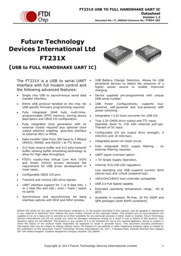
FT230X USB TO BASIC UART ICVersion 1.1Document No.: FT 000566 Clearance No.: FTDI# 2602FT230X Block DiagramVCC1V8 InternalCore Supply3V3OUTUSBDPUSBDM3.3 Volt LDORegulatorUSBTransceiverwithIntegrated1.5k pullupsand batterychargedetection48MHz1.8 Volt LDORegulatorFIFO RX Buffer(512 bytes)Baud RateGeneratorTXDRXDRTS#CTS#Serial InterfaceEngine(SIE)USBProtocol EngineUART FIFOControllerUART ControllerwithProgrammableSignal InversionCBUS0CBUS1CBUS2CBUS3Internal MTPMemoryUSB DPLLFIFO TX Buffer(512 bytes)Internal12MHzOscillator3V3OUTRESET#X4 ClockMultiplierResetGenerator48MHzTo USB Transceiver CellGNDFigure 2.1 FT230X Block DiagramFor a description of each function please refer to Section 4.Copyright 2012 Future Technology Devices International Limited4
FT230X USB TO BASIC UART ICVersion 1.1Document No.: FT 000566 Clearance No.: FTDI# 260Table of Contents1Typical Applications . 21.1Driver Support . 21.2Part Numbers. 21.3USB Compliant . 32FT230X Block Diagram . 43Device Pin Out and Signal Description . 73.116-LD QFN Package . 73.1.13.216-LD SSOP Package. 93.2.13.34QFN Package PinOut Description . 7SSOP Package PinOut Description . 9CBUS Signal Options . 11Function Description. 134.1Key Features . 134.2Functional Block Descriptions . 135Devices Characteristics and Ratings . 165.1Absolute Maximum Ratings. 165.2ESD and Latch-up Specifications . 165.3DC Characteristics. 175.4MTP Memory Reliability Characteristics . 215.5Internal Clock Characteristics . 216USB Power Configurations . 226.1USB Bus Powered Configuration . 226.2Self Powered Configuration . 236.3USB Bus Powered with Power Switching Configuration . 247Application Examples . 257.1USB to RS232 Converter . 257.2USB to RS485 Coverter . 267.3USB to RS422 Converter . 277.4USB Battery Charging Detection . 287.5LED Interface . 318Internal MTP Memory Configuration . 328.1Default Values . 328.2Methods of Programming the MTP Memory . 338.2.18.3Programming the MTP memory over USB . 33Memory Map . 34Copyright 2012 Future Technology Devices International Limited5
FT230X USB TO BASIC UART ICVersion 1.1Document No.: FT 000566 Clearance No.: FTDI# 2609Package Parameters . 359.1SSOP-16 Package Mechanical Dimensions . 359.2SSOP-16 Package Markings . 369.3QFN-16 Package Mechanical Dimensions . 379.4QFN-16 Package Markings . 389.5Solder Reflow Profile . 3910Contact Information . 40Appendix A – References . 41Appendix B - List of Figures and Tables . 42Appendix C - Revision History . 44Copyright 2012 Future Technology Devices International Limited6
FT230X USB TO BASIC UART ICVersion 1.1Document No.: FT 000566 Clearance No.: FTDI# 2603Device Pin Out and Signal Description3V3OUT761TXDRXDRTS#CTS#VCCIO8VCC103.1 16-LD QFN NDGNDUSBDMUSBDP152164Figure 3.1 QFN Schematic Symbol3.1.1 QFN Package PinOut DescriptionNote : # denotes an active low signal.Pin No.NameType**POWERInput10VCC1VCCIO3V3OUT3, 13Input5 V (or 3V3) supply to IC1V8 - 3V3 supply for the IO cells3V3 output at 50mA. May be used to power hen VCC is 3V3; pin 8 is an input pin and should beconnected to pin 10.0V Ground input.Table 3.1 Power and Ground*Pin 17 is the centre pad under the IC. Connect to GND.** If VCC is 3V3 then 3V3OUT must also be driven with 3V3 inputPin No.NameTypeDescription7USBDMINPUTUSB Data Signal Minus.6USBDPINPUTUSB Data Signal Plus.9RESET#INPUTReset input (active low).Table 3.2 Common Function pinsCopyright 2012 Future Technology Devices International Limited7
FT230X USB TO BASIC UART ICVersion 1.1Document No.: FT 000566 Clearance No.: FTDI# 260Pin No.NameTypeDescription15TXDOutputTransmit Asynchronous Data Output.2RXDInputReceiving Asynchronous Data Input.16RTS#Output4CTS#Input12CBUS0I/OConfigurable CBUS I/O Pin. Function of this pin is configured in thedevice MTP memory. The default configuration is TXDEN. See CBUSSignal Options, Table 3.7.11CBUS1I/OConfigurable CBUS I/O Pin. Function of this pin is configured in thedevice MTP memory. The default configuration is RXLED#. See CBUSSignal Options, Table 3.7.5CBUS2I/OConfigurable CBUS I/O Pin. Function of this pin is configured in thedevice MTP memory. The default configuration is TXLED#. See CBUSSignal Options, Table 3.7.14CBUS3I/OConfigurable CBUS I/O Pin. Function of this pin is configured in thedevice MTP memory. The default configuration is SLEEP#. See CBUSSignal Options, Table 3.7.Request to Send Control Output / Handshake Signal.Clear To Send Control Input / Handshake Signal.Table 3.3 UART Interface and CBUS Group (see note 1)Notes:1. When used in Input Mode, the input pins are pulled to VCCIO via internal 75kΩ (approx) resistors.These pins can be programmed to gently pull low during USB suspend (PWREN# “1”) by setting anoption in the MTP memory.Copyright 2012 Future Technology Devices International Limited8
FT230X USB TO BASIC UART ICVersion 1.1Document No.: FT 000566 Clearance No.: FTDI# 2603V3OUT983TXDRXDRTS#CTS#VCCIOU?10VCC123.2 16-LD SSOP S1311GNDUSBDMUSBDP1426Figure 3.2 SSOP Schematic Symbol3.2.1 SSOP Package PinOut DescriptionNote: # denotes an active low signal.Pin No.NameType**POWERInput12VCC3VCCIO3V3OUT5, 13Input5 V (or 3V3) supply to IC1V8 - 3V3 supply for the IO cells3V3 output at 50mA. May be used to power When VCC is 3V3; pin 10 is an input pin and should beconnected to pin 12.0V Ground input.Table 3.4 Power and Ground** If VCC is 3V3 then 3V3OUT must also be driven with 3V3 inputPin No.NameTypeDescription9USBDMINPUTUSB Data Signal Minus.8USBDPINPUTUSB Data Signal Plus.11RESET#INPUTReset input (active low).Table 3.5 Common Function pinsPin No.NameTypeDescription1TXDOutputTransmit Asynchronous Data Output.4RXDInputReceiving Asynchronous Data Input.Copyright 2012 Future Technology Devices International Limited9
FT230X USB TO BASIC UART ICVersion 1.1Document No.: FT 000566 Clearance No.: FTDI# 2602RTS#OutputRequest to Send Control Output / Handshake Signal.6CTS#Input15CBUS0I/OConfigurable CBUS I/O Pin. Function of this pin is configured in thedevice MTP memory. The default configuration is TXDEN. See CBUSSignal Options, Table 3.7.14CBUS1I/OConfigurable CBUS I/O Pin. Function of this pin is configured in thedevice MTP memory. The default configuration is RXLED#. See CBUSSignal Options, Table 3.7.7CBUS2I/OConfigurable CBUS I/O Pin. Function of this pin is configured in thedevice MTP memory. The default configuration is TXLED#. See CBUSSignal Options, Table 3.7.16CBUS3I/OConfigurable CBUS I/O Pin. Function of this pin is configured in thedevice MTP memory. The default configuration is SLEEP#. See CBUSSignal Options, Table 3.7.Clear To Send Control Input / Handshake Signal.Table 3.6 UART Interface and CBUS Group (see note 1)Notes:1. When used in Input Mode, the input pins are pulled to VCCIO via internal 75kΩ (approx) resistors.These pins can be programmed to gently pull low during USB suspend (PWREN# “1”) by setting anoption in the MTP memory.Copyright 2012 Future Technology Devices International Limited10
FT230X USB TO BASIC UART ICVersion 1.1Document No.: FT 000566 Clearance No.: FTDI# 2603.3 CBUS Signal OptionsThe following options can be configured on the CBUS I/O pins. CBUS signal options are common to bothpackage versions of the FT230X. These options can be configured in the internal MTP memory using thesoftware utility FT PROG or MPROG, which can be downloaded from the FTDI Utilities(www.ftdichip.com). The default configuration is described in Section 8.CBUS SignalOptionAvailable On CBUS PinTRI-STATECBUS0, CBUS1, CBUS2, CBUS3IO Pad is tri-statedDRIVE 1CBUS0, CBUS1, CBUS2, CBUS3Output a constant 1DRIVE 0CBUS0, CBUS1, CBUS2, CBUS3Output a constant 0TXDENCBUS0, CBUS1, CBUS2, CBUS3Enable transmit data for RS485PWREN#CBUS0, CBUS1, CBUS2, CBUS3Output is low after the device has been configured byUSB, then high during USB suspend mode. This outputcan be used to control power to external logic P-Channellogic level MOSFET switch. Enable the interface pull-downoption when using the PWREN# in this way.TXLED#CBUS0, CBUS1, CBUS2, CBUS3Transmit data LED drive – pulses low when transmittingdata via USB. See Section 7.5 for more details.RXLED#CBUS0, CBUS1, CBUS2, CBUS3Receive data LED drive – pulses low when receiving datavia USB. See Section 7.5 for more details.TX&RXLED#CBUS0, CBUS1, CBUS2, CBUS3LED drive – pulses low when transmitting or receivingdata via USB. See Section 7.5 for more details.SLEEP#CBUS0, CBUS1, CBUS2, CBUS3Goes low during USB suspend mode. Typically used topower down an external TTL to RS232 level converter ICin USB to RS232 converter designs.CLK24MHzCBUS0, CBUS1, CBUS2, CBUS324 MHz Clock output.*CLK12MHzCBUS0, CBUS1, CBUS2, CBUS312 MHz Clock output.*CLK6MHzCBUS0, CBUS1, CBUS2, CBUS36 MHz Clock output.*GPIOCBUS0, CBUS1, CBUS2, CBUS3CBUS bit bang mode option. Allows up to 4 of the CBUSpins to be used as general purpose I/O. Configuredindividually for CBUS0, CBUS1, CBUS2 and CBUS3 in theinternal MTP memory. A separate application note,AN232R-01, available from FTDI website(www.ftdichip.com) describes in more detail how to useCBUS bit bang mode.BCD ChargerCBUS0, CBUS1, CBUS2, CBUS3Battery charge Detect, indicates when the device isconnected to a dedicated battery charger host. Activehigh output.BCD Charger#CBUS0, CBUS1, CBUS2, CBUS3Inverse of BCD ChargerBitBang WR#CBUS0, CBUS1, CBUS2, CBUS3Synchronous and asynchronous bit bang mode WR#strobe output.BitBang RD#CBUS0, CBUS1, CBUS2, CBUS3Synchronous and asynchronous bit bang mode RD#strobe output.DescriptionCopyright 2012 Future Technology Devices International Limited11
FT230X USB TO BASIC UART ICVersion 1.1Document No.: FT 000566 Clearance No.: FTDI# 260CBUS SignalOptionAvailable On CBUS PinVBUS SenseCBUS0, CBUS1, CBUS2, CBUS3Input to detect when VBUS is present.Time StampCBUS0, CBUS1, CBUS2, CBUS3Toggle signal which changes state each time a USBSOF is receivedKeep Awake#CBUS0, CBUS1, CBUS2, CBUS3Prevents the device from entering suspend statewhen unplugged.DescriptionTable 3.7 CBUS Configuration Control*When in USB suspend mode the outputs clocks are also suspended.Copyright 2012 Future Technology Devices International Limited12
FT230X USB TO BASIC UART ICVersion 1.1Document No.: FT 000566 Clearance No.: FTDI# 2604Function DescriptionThe FT230X is a compact USB to a basic serial UART interface device which simplifies USBimplementations in a small optimised package, with minimum UART signals and reduces externalcomponent count by fully integrating an MTP memory, and an integrated clock circuit which requires noexternal crystal. It has been designed to operate efficiently with USB host controllers by using as littlebandwidth as possible when compared to the total USB bandwidth available.4.1 Key FeaturesFunctional Integration. Fully integrated MTP memory, clock generation, AVCC filtering, Power-OnReset (POR) and LDO regulators.Configurable CBUS I/O Pin Options. The fully integrated MTP memory allows configuration of theControl Bus (CBUS) functionality and drive strength selection. There are 4 configurable CBUS I/O pins.These configurable options are detailed in section 3.3The CBUS lines can be configured with any one of these output options by setting bits in the internal MTPmemory. The device is shipped with the most commonly used pin definitions pre-programmed - seeSection 8 for details.Asynchronous Bit Bang Mode with RD# and WR# Strobes. The FT230X supports FTDI‟s previouschip generation bit-bang mode. In bit-bang mode, the four UART lines can be switched from the regularinterface mode to a 4-bit general purpose I/O port. Data packets can be sent to the device and they willbe sequentially sent to the interface at a rate controlled by an internal timer (equivalent to the baud ratepre-scalar). In the FT230X device this mode has been enhanced by outputting the internal RD# and WR#strobes signals which can be used to allow external logic to be clocked by accesses to the bit-bang I/Obus. This option will be described more fully in a separate application note available from FTDI website(www.ftdichip.com).Synchronous Bit Bang Mode. The FT230X supports synchronous bit bang mode. This mode differs fromasynchronous bit bang mode in that the interface pins are only read when the device is written to. Thismakes it easier for the controlling program to measure the response to an output stimulus as the datareturned is synchronous to the output data. An application note, AN232R-01, available from FTDI website(www.ftdichip.com) describes this feature.Source Power and Power Consumption. The FT230X is capable of operating at a voltage supplybetween 3.3V and 5.25V with a nominal operational mode current of 8mA and a nominal USB suspendmode current of 125µA. This allows greater margin for peripheral designs to meet the USB suspend modecurrent limit of 2.5mA. An integrated level converter within the UART interface allows the FT230X tointerface to UART logic running at 1.8V to 3.3V (5V tolerant).4.2 Functional Block DescriptionsThe following paragraphs detail each function within the FT230X. Please refer to the block diagram shownin Figure 2.1Internal MTP Memory. The internal MTP memory in the FT230X is used to store USB Vendor ID (VID),Product ID (PID), device serial number, product description string and various other USB configurationdescriptors. The internal MTP memory is also used to configure the CBUS pin functions. The FT230X issupplied with the internal MTP memory pre-programmed as described in Section 8. A user area of theinternal MTP memory is available to system designers to allow storing additional data from the userapplication over USB. The internal MTP memory descriptors can be programmed in circuit, over USBwithout any additional voltage requirement. The descriptors can be programmed using the FTDI utilitysoftware called FT PROG, which can be downloaded from FTDI Utilities on the FTDI website(www.ftdichip.com). 3.3V LDO Regulator. The 3.3V LDO regulator generates the 3.3V reference voltage for driving theUSB transceiver cell output buffers. It requires an external decoupling capacitor to be attached to the3V3OUT regulator output pin. It also provides 3.3V power to the 1.5kΩ internal pull up resistor onUSBDP. The main function of the LDO is to power the USB Transceiver and the Reset Generator Cellsrather than to power external logic. However, it can be used to supply external circuitry requiring a 3.3V nominal supply with a maximum current of 50mA. 1.8V LDO Regulator. The 1.8V LDO regulator generates the 1.8V reference voltage for internal usedriving the IC core functions of the serial interface engine and USB protocol engine.Copyright 2012 Future Technology Devices International Limited13
FT230X USB TO BASIC UART ICVersion 1.1Document No.: FT 000566 Clearance No.: FTDI# 260USB Transceiver. The USB Transceiver Cell provides the USB 1.1 / USB 2.0 full-speed physical interfaceto the USB cable. The output drivers provide 3.3V level slew rate control signalling, whilst a differentialinput receiver and two single ended input receivers provide USB data in, Single-Ended-0 (SE0) and USBreset detection conditions respectfully. This function also incorporates a 1.5kΩ pull up resistor on USBDP.The block also detects when connected to a USB power supply which will not enumerate the device butstill supply power and may be used for battery charging.USB DPLL. The USB DPLL cell locks on to the incoming NRZI USB data and generates recovered clockand data signals for the Serial Interface Engine (SIE) block.Internal 12MHz Oscillator - The Internal 12MHz Oscillator cell generates a 12MHz reference clock. Thisprovides an input to the x4 Clock Multiplier function. The 12MHz Oscillator is also used as the referenceclock for the SIE, USB Protocol Engine and UART FIFO controller blocks.Clock Multiplier / Divider. The Clock Multiplier / Divider takes the 12MHz input from the InternalOscillator function and generates the 48MHz, 24MHz, 12MHz and 6MHz reference clock signals. The 48Mzclock reference is used by the USB DPLL and the Baud Rate Generator blocks.Serial Interface Engine (SIE). The Serial Interface Engine (SIE) block performs the parallel to serialand serial to parallel conversion of the USB data. In accordance with the USB 2.0 specification, itperforms bit stuffing/un-stuffing and CRC5/CRC16 generation. It also verifies the CRC on the USB datastream.USB Protocol Engine. The USB Protocol Engine manages the data stream from the device USB controlendpoint. It handles the low level USB protocol requests generated by the USB host controller and thecommands for controlling the functional parameters of the UART in accordance with the USB 2.0specification chapter 9.FIFO RX Buffer (512 bytes). Data sent from the USB host controller to the UART via the USB data OUTendpoint is stored in the FIFO RX (receive) buffer. Data is removed from the buffer to the UART transmitregister under control of the UART FIFO controller. (Rx relative to the USB interface).FIFO TX Buffer (512 bytes). Data from the UART receive register is stored in the TX buffer. The USBhost controller removes data from the FIFO TX Buffer by sending a USB request for data from the devicedata IN endpoint. (Tx relative to the USB interface).UART FIFO Controller. The UART FIFO controller handles the transfer of data between the FIFO RX andTX buffers and the UART transmit and receive registers.UART Controller with Programmable Signal Inversion and High Drive. Together with the UARTFIFO Controller the UART Controller handles the transfer of data between the FIFO RX and FIFO TXbuffers and the UART transmit and receive registers. It performs asynchronous 7 or 8 bit parallel to serialand serial to parallel conversion of the data on the RS232 (or RS422 or RS485) interface.Control signals supported by UART mode include RTS, CTS. The UART Controller also provides atransmitter enable control signal pin option (TXDEN) to assist with interfacing to RS485 transceivers.RTS/CTS and XON / XOFF handshaking options are also supported. Handshaking is handled in hardware toensure fast response times. The UART interface also supports the RS232 BREAK setting and detectionconditions.Additionally, the UART signals can each be individually inverted and have a configurable high drivestrength capability (using FT PROG). Both these features are configurable in the MTP memory.Baud Rate Generator - The Baud Rate Generator provides a 16x clock input to the UART Controllerfrom the 48MHz reference clock. It consists of a 14 bit pre-scalar and 3 register bits which provide finetuning of the baud rate (used to divide by a number plus a fraction or “sub-integer”). This determines thebaud rate of the UART, which is programmable from 183 baud to 3 Mbaud.The FT230X supports all standard baud rates and non-standard baud rates from 183 Baud up to 3Mbaud. Achievable non-standard baud rates are calculated as follows Baud Rate 3000000 / (n x)where „n‟ can be any integer between 2 and 16,384 ( 2 ) and „x’ can be a sub-integer of the value 0,0.125, 0.25, 0.375, 0.5, 0.625, 0.75, or 0.875. When n 1, x 0, i.e. baud rate divisors with valuesbetween 1 and 2 are not possible.14This gives achievable baud rates in the range 183.1 baud to 3,000,000 baud. When a non-standard baudrate is required simply pass the required baud rate value to the driver as normal, and the FTDI driver willcalculate the required divisor, and set the baud rate. See FTDI application note AN232B-05 on the FTDIwebsite (www.ftdichip.com) for more details.Copyright 2012 Future Technology Devices International Limited14
FT230X USB TO BASIC UART ICVersion 1.1Document No.: FT 000566 Clearance No.: FTDI# 260RESET Generator - The integrated Reset Generator Cell provides a reliable power-on reset to the deviceinternal circuitry at power up. The RESET# input pin allows an external device to reset the FT230X.RESET# can be tied to VCC or left unconnected if not being used.Copyright 2012 Future Technology Devices International Limited15
FT230X USB TO BASIC UART ICVersion 1.1Document No.: FT 000566 Clearance No.: FTDI# 2605Devices Characteristics and Ratings5.1 Absolute Maximum RatingsThe absolute maximum ratings for the FT230X devices are as follows. These are in accordance with theAbsolute Maximum Rating System (IEC 60134). Exceeding these may cause permanent damage to thedevice.ParameterValueUnitStorage Temperature-65 C to 150 CDegrees CConditions168 HoursFloor Life (Out of Bag) At Factory Ambient(30 C / 60% Relative Humidity)(IPC/JEDEC JSTD-033A MSLLevel 3Compliant)*Ambient Operating Temperature (PowerApplied)-40 C to 85 CDegrees CMTTF FT230XSTBDHoursMTTF FT230XQTBDHoursVCC Supply Voltage-0.3 to 5.5VVCCIO IO Voltage-0.3 to 4.0VDC Input Voltage – USBDP and USBDM-0.5 to 3.63V-0.3 to 5.8V22mADC Input Voltage – High ImpedanceBi-directionals (powered from VCCIO)DC Output Current – OutputsHoursTable 5.1 Absolute Maximum Ratings* If devices are stored out of the packaging beyond this time limit the devices should be baked beforeuse. The devices should
FT230X USB TO BASIC UART IC Version 1.1 Document No.: FT_000566 Clearance No.: FTDI# 260 Future Technology Devices International Ltd. FT230X (USB to BASIC UART IC) The FT230X is a USB to serial UART interface with optimised pin count for smaller PCB designs and the following advanced features: