Transcription
Fundamentals ofattitude EstimationPreparedbyA.KaviyarasuAssistant ProfessorDepartment of Aerospace EngineeringMadras Institute Of TechnologyChromepet, Chennai
Basically an IMU can used for two main purposes– To measure aircraft attitude information ( Pitch, Roll and yaw) Accelerometers to measure pith and roll information Gyroscope to measure pitch, roll and yaw information Magnetometer to measure pitch and roll information– To measure aircraft position information (Dead Reckoning) Stable platform (Gyros and Accelerometer are mounted on a gimbal platform) Strap down platform (Gyros and Accelerometer are Strapped it on body of anaircraft)Kaviyarasu A, MIT Aerospace, Chennai
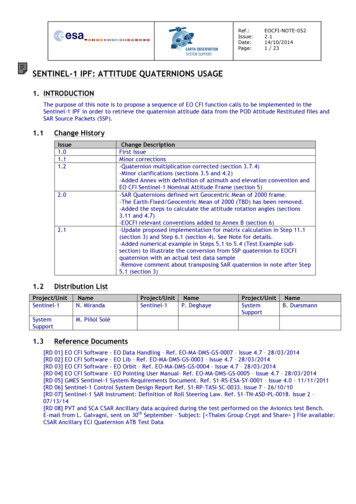
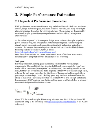
PitchRollKaviyarasu A, MIT Aerospace, ChennaiYaw
Estimation of Angle withAccelerometer Three-axis accelerometer can be modeled as1am F Fg mam measured accelerationm mass of the bodyF sum of all forces acts on body expressed in bodyframe(includesgravity)Fg Force due to gravity expressed in bodyframeKaviyarasu A, MIT Aerospace, Chennai
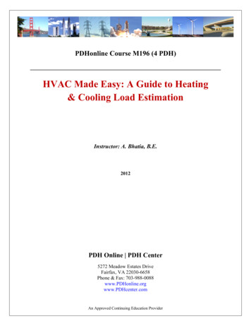
we assume that F 0 then the output of accelerometer is Fgam m 0 In inertial frame force of gravity is expressed as 0 mg Rotating the gravity into the body frame of the sensor 0 - mg sin( ) Fg RIB 0 mg cos( )sin( ) mg mg cos( ) cos( ) Kaviyarasu A, MIT Aerospace, Chennai
The expected accelerometer data in the body frame is defined byg sin( ) am -g cos( )sin( ) -g cos( ) cos( ) Let the component of acceleration is defined by its axis amx g accel arc sin amy amz accel arctan Kaviyarasu A, MIT Aerospace, Chennai
The measured angles are only the estimated angles not the actual angels. This method provides quick and very simple way of estimating pitch and rollangle from the accelerometer. However we assumed that the forces acting on the accelerometer was onlygravity. Vibration and other external forces will affect our pitch and roll anglemeasurement.Kaviyarasu A, MIT Aerospace, Chennai
Estimation of Angle withGyroscope Rate gyro can also be used to measure the attitude of vehicle. unlikeaccelerometer rate gyros are not affect by external acceleration and externalforces. Gyro based measurement is immune to external forces. Since roll, pitch, and yaw each occur in different reference frames, we need totake the rate gyro outputs and rotate them into the appropriate frames in order toget the Euler's rate.Kaviyarasu A, MIT Aerospace, Chennai
. p q sin tan( ) r cos tan( ) . q cos r sin . sin cos q r cos cos gyro gyro gyro gyro gyro . (dt * ). (dt * ) gyro. (dt * )This method helps to use rate gyros to estimate angles that are not sensitive to vibrationand other external forces. However rate gyros are noisy and imperfect, every time weadd new gyro measurements, we add errors to our angle estimates. Over time, errors willaccumulate, causing our gyro-based angles estimates to drift over time.Kaviyarasu A, MIT Aerospace, Chennai
Combining accelerometer and rateGyro data Angle estimate based on rate gyros alone drift over time, making them unreliablein the long-term purpose or application. Angle estimates based on accelerometers do not cause angle estimates to drift, butthey are sensitive to external forces like vibration, making short-term estimatesunreliable. Here we are going to discuss about how to combine the outputs of both types ofsensor to produce angle estimates that are resistant to both vibration and immuneto long-term drift. Here the step is classified into two types– Prediction (by using gyroscope reading to measure incremental changes in theangle).Kaviyarasu A, MIT Aerospace, Chennai
Estimation (by means of using accelerometer reading to correct the rate gyrodrift). In updating step we assume accelerometer based angle estimation is close to truevalue . We take the measured angle (from the accelerometers) and the predicted angle(from the rate gyros), compute the difference, and add a portion of the differenceto the final angle estimate. estimate gyro L accel gyro estimate gyro L accel gyro estimate gyro L mag gyro Kaviyarasu A, MIT Aerospace, Chennai
L is numeric value between 0 and 1.if L 0 gyro based angle mesurement is used(accelerometer measurment become zero)if L 1 accelerometer based angle mesurement is used(gyros measurment become zero) As approaches L 1, the accelerometers are trusted more and the rate gyros are trustedless. This makes the angle estimates less sensitive to rate gyro noise and biases, butmore sensitive to vibration and other external forces. As approaches L 0, rate gyros are trusted more and the accelerometers are trustedless. This makes the angle estimates more sensitive to rate gyro noise and biases, butless sensitive to vibration and other external forces.Kaviyarasu A, MIT Aerospace, Chennai
This formulation can be called a “fixed-gain observer” and it looks similar to thatof Complementry Filter and Kalman Filter. The main difference is that in a Kalman Filter, the observer gain is selectedoptimally using known characteristics of the physical system. In addition, a Kalman Filter can exploit knowledge of the physical system so thataccelerometer data (and other data) needn’t be converted to angles before using itto make corrections to the angle estimates.Kaviyarasu A, MIT Aerospace, Chennai
Complementary filterangle 0.98*(angle gyrodata*dt) 0.02*(accData);Kaviyarasu A, MIT Aerospace, Chennai
Is Accelerometer helpsto measure velocityand position?Kaviyarasu A, MIT Aerospace, Chennai
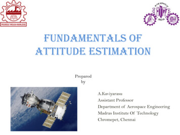
The answer is yes and no . It depends upon how much accuracy we are in needed for our application. The low cost accelerometer are very less in accuracy result in every poorestimation in position and velocity. The accuracy not only because of low cost sensor but also for misalignment ofsensor position in the body frame. Small misalignment errors may leads to higherrors in acceleration measurement, which translate into more error in velocityestimation and much more error in position estimate.Kaviyarasu A, MIT Aerospace, Chennai
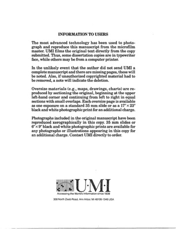
Estimation of Positionand velocityVi aiPi aiVi inertial frame VelocityPi inertial frame Positionai Inertial frame accelerationBut in practicalVi Vi (dt * ai )Vi dt * aiPi Pi (dt *Vi )Pi dt *ViKaviyarasu A, MIT Aerospace, Chennai
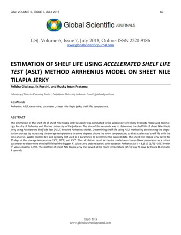
Expected Accuracy of Velocityand Position EstimatesKaviyarasu A, MIT Aerospace, Chennai
How to reduce the error? Reduce the Distortions caused by an Accelerometer.Reduce the Distortions caused by gyroscope.Reduce the Distortions caused by Magnetometer.By using any sensor fusion technique. (Eg.GPS INS Integration).Kaviyarasu A, MIT Aerospace, Chennai
Distortions by Accelerometer The simplified accelerometer mentioned in the above equation will notconsider the account of cross-axis misalignment, temperature varyingoutput bias and scale factors. All these factor will affects accelerometersensor output and affect accuracy of velocity and positionmeasurement. The more complete model of the accelerometer is given below 1 am Ma Sa (T )(F Fg) (t) m Ma acceleration misalignment matrix (t) Vector of temperature varying biasSa (T ) Diagonal temperature varying accelerometerSensitivity matrixKaviyarasu A, MIT Aerospace, Chennai
0 Sax 0 Sa (T ) 0 Say 0 00 Saz The sensitivity matrix encodes expected accelerometer raw output for agiven measured acceleration. The misalignment matrix describes the effect of cross-axismisalignment unlike bias and sensitivity terms, it is not affected betemperature.Kaviyarasu A, MIT Aerospace, Chennai
When using accelerometer data, we measure only value, is am but whatwe really needed is the actual acceleration amc before scale factors,biases, and misalignment distort the measurement. That is, we want totake the measurement and extract the term . Solving, we getamcamc Sa 1 (T ) Ma 1am a(T ) amc corrected accelerometer measurement vectorIn order to obtain the best accuracy, the terms should be determinedexperimentally over the full operating temperature of the sensorKaviyarasu A, MIT Aerospace, Chennai
Distortions by Gyroscope Let the Vector P is defined as p p q r P Sg 1 (T ) Mg 1 pm g (T ) Cga* amc pm measured angular rate vectorCga matrix encoding the sensitivityof rate gyro axes to accelerationamc corrected accelerometer measurement Usually coupling between the acceleration and rate gyro output Cga is small enoughthat can be neglected, but in high acceleration is expected (e.g. on a rocket), this term mustbe measured and included in the model for the best accuracy.Kaviyarasu A, MIT Aerospace, Chennai
Distortions by Magnetometer Magnetometer are very trick one to calibrate. Like accelerometer and gyroscope magnetometer also subject to cross-axismisalignment, output bias ,scale factors. In addition to that, local magnetic field around the magnetometer can be distortedby magnetic and ferrous metal objects. This distortion must be measured andcorrected in order for the magnetometer to be useful. The field can also be distorted by time-varying electromagnetic waves from highpower electrical lines and communication lines placed near the sensor. Finally, as the sensor is moved around in practice, the field can be distorted sothat, in certain locations (say, next to a concrete wall filled with rebar), theaccuracy of the measurement is reduced.Kaviyarasu A, MIT Aerospace, Chennai
b Sb 1 (T ) Mb 1bm b(T ) b magnetic fieldbm Measured magnetic fieldSb 1 inverse of the magnetometer sensitive matrixMb 1 inverse of the magnetometer misalignment matrix b(T ) magnetometer bias vector After the magnetometer measurement is corrected for axis misalignment, scalefactor, and bias errors, it must be corrected for additional local magnetic fielddistortions.Kaviyarasu A, MIT Aerospace, Chennai
Two types of local distortions are there– Soft-Iron Distortion.– Hard -Iron Distortion. A soft-iron field distortion is caused by ferrous metal objects that bend the Earth’smagnetic field e.g. Screws A hard-iron distortion is caused by near by object having its own magnetic fieldlike permanent magnets motor or current carrying conductors. In the absence of any hard or soft-iron distortions, the outputs of the magnetometeras it is rotated should trace out a perfect sphere centered around zero. Soft-iron distortions distort the sphere so that it appears to be an ellipsoid. Hardiron distortions shift the mean of the sphere away from zeroKaviyarasu A, MIT Aerospace, Chennai
One way to calibrate the magnetometer for hard and soft iron distortions is to fitan ellipsoid to a set of magnetometer data collected over a wide variety ofdifferent orientations. The center of the ellipsoid is equivalent to the bias causedby hard iron distortions, while the ellipsoid shape on the x, y, and z axes arecaused by the soft-iron distortions. A correction matrix can then be calculatedthat, when multiplied by the magnetometer measurements, alters the ellipsoid sothat it looks like a sphere again.Kaviyarasu A, MIT Aerospace, Chennai
Sensor data fusionKaviyarasu A, MIT Aerospace, Chennai
The sensor fusion can be implemented by some of the steps below-Complementary Filter (CF)-Kalman Filter (KF)-Extended Kalman Filter (EKF)-Unscented Kalman Filter (UKF)-Particle Filter (PF)Kaviyarasu A, MIT Aerospace, Chennai
Nothing but fusion of data’s from two or more sensor. The data measured from a single sensor not gives accurate measurement ofreading. It may suffer from some noise ,errors ,misalignment and externaldisturbance. In order to measure the exact physical quantity of data ,two or more sensors areused. these data's are fused in such a way it will provide original measurement ofthe physical quantity.Kaviyarasu A, MIT Aerospace, Chennai
Combining accelerometer and rateGyro data Angle estimates based on rate gyros alone drift over time, making them unreliablein the long-term purpose or application. Angle estimates based on accelerometers do not cause angle estimates to drift, butthey are sensitive to external forces like vibration, making short-term estimatesunreliable. Here we are going to discuss about how to combine the outputs of both types ofsensor to produce angle estimates that are resistant to both vibration and immuneto long-term drift. Here the step is classified into two types– Prediction (by using gyroscope reading to measure incremental changes in theangle).Kaviyarasu A, MIT Aerospace, Chennai
Estimation (by means of using accelerometer reading to correct the rate gyrodrift). In updating step we assume accelerometer based angle estimation is close to truevalue . We take the measured angle (from the accelerometers) and the predicted angle(from the rate gyros), compute the difference, and add a portion of the differenceto the final angle estimate. estimate gyro L accel gyro estimate gyro L accel gyro estimate gyro L mag gyro Kaviyarasu A, MIT Aerospace, Chennai
L is numeric value between 0 and 1.if L 0 gyro based angle mesurement is used(accelerometer measurment become zero)if L 1 accelerometer based angle mesurement is used(gyros measurment become zero) As approaches L 1, the accelerometers are trusted more and the rate gyros are trustedless. This makes the angle estimates less sensitive to rate gyro noise and biases, butmore sensitive to vibration and other external forces. As approaches L 0, rate gyros are trusted more and the accelerometers are trustedless. This makes the angle estimates more sensitive to rate gyro noise and biases, b
Fundamentals of attitude Estimation A.Kaviyarasu Assistant Professor Department of Aerospace Engineering Madras Institute Of Technology Chromepet, Chennai Prepared by Basically an IMU can used for two main purposes –To measure aircraft attitude information ( Pitch, Roll and yaw) Accelerometers to measure pith and roll information Gyroscope to measure pitch, roll and yaw