Transcription
IntroductionThis two-part application note series reviews new developments in the Fourth Generation Long Term Evolution (4G-LTE) cellularstandard. The application note series explores LTE-Advanced (LTE-A) Release-12 (Rel-12) features and the impact on eNodeBradio frequency (RF) transmitters. The application notes reveal how analog integration can overcome design challenges arisingfrom the latest 4G developments. A Glossary of Technical Terms is appended to the end of each application note.Part 1, this application note, examines market forces driving global adoption of the LTE standard and trends in 4G radio accesstechnology. Readers will learn about work items outlined in the 3rd Generation Partnership Project (3GPP) Rel-12 specification.Topics include carrier aggregation (CA), spatial multiplexing, and active antenna systems (AAS).Part 2 of this series will explore the analog integration challenges in 4G base stations. Rel-12 features such as widebanddownlink carrier aggregation, downlink multiple-input multiple-out (MIMO) spatial multiplexing, and AAS with embedded RF,present new design challenges in next-generation eNodeB radios. A disruptive bits-to-RF solution is introduced that can helpengineers shape alternative radio transmitter architectures. The discussion focuses on novel RF digital-to-analog converter (RFDAC) technology that yields a single-chip, wideband RF transmitter solution. Readers will learn about system-level applications ofthe RF-DAC and the integration benefits that it delivers to eNodeB radio design.OverviewLong-Term Evolution (LTE) is recognized as the fastest growing mobile broadband technology, and becoming the most widelyadopted cellular standard worldwide. LTE's global rate of adoption by wireless service providers has exceeded prior secondgeneration (2G) and third-generation (3G) deployments. The popularity of LTE is mainly due to its high spectral efficiency andhigh peak data rates, low-latency IP-based network, and evolutionary roadmap. For consumers, this translates to reliable highspeed mobile access and anywhere-anytime connectivity. For wireless service providers, LTE offers efficient spectrum utilization,network capacity gains and significant improvements in total cost of ownership (TCO). But LTE is not "true 4G" service and istechnically still considered 3.9G.The true fourth-generation (4G) radio communication standard, known as International Mobile Telecommunications-Advanced(IMT-Advanced), must meet the requirements set forth by the International Telecommunication Union Radio Sector (ITU-R).Page 1 of 13
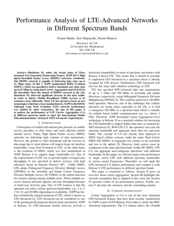
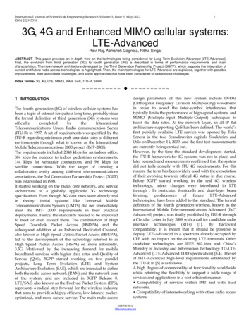
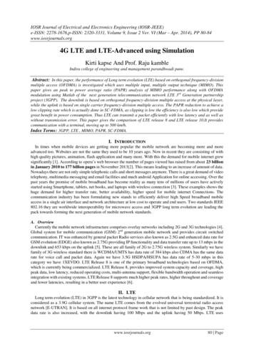
adopted cellular standard worldwide. LTE's global rate of adoption by wireless service providers has exceeded prior secondgeneration (2G) and third-generation (3G) deployments. The popularity of LTE is mainly due to its high spectral efficiency andhigh peak data rates, low-latency IP-based network, and evolutionary roadmap. For consumers, this translates to reliable highspeed mobile access and anywhere-anytime connectivity. For wireless service providers, LTE offers efficient spectrum utilization,network capacity gains and significant improvements in total cost of ownership (TCO). But LTE is not "true 4G" service and istechnically still considered 3.9G.The true fourth-generation (4G) radio communication standard, known as International Mobile Telecommunications-Advanced(IMT-Advanced), must meet the requirements set forth by the International Telecommunication Union Radio Sector (ITU-R). IMTAdvanced defines 4G as a service that delivers 100Mbps peak data rates to high-mobility users, and 1Gbps peak data rates forlow-mobility clients. To comply with the IMT-Advanced vision, the 3GPP has developed many enhancements since the initialLTE Rel-8 standard published in 2008.In Rel-10 the 3GPP introduced LTE-Advanced as "true 4G" service to meet or exceed the IMT-Advanced requirements. LTE-ARel-10 was the next step in the mobile broadband evolution and further expanded on LTE's basic feature set. Presently, Rel-12is close to introduction with a functional freeze date planned for March 2015. Rel-12 will include evolutionary enhancementsacross radio access technology. Figure 1 illustrates LTE development timelines where it can be seen that theoretical peakdownlink (DL) and uplink (UL) data rates have increased about 10x and 20x, respectively, from DL 300Mbps/UL 75Mbps inRel-8 to DL 3Gbps/UL 1.5Gbps in Rel-10. The extraordinary increase in peak data rates is due in part to wideband CA,complimented by multilayer spatial multiplexing introduced in Rel-10 and now an important part of Rel-12 enhancements.Figure 1. LTE release timeline showing evolutionary advancements in radio access techology.LTE-A Rel-12 and the Impact on eNodeB RadiosRel-12 enhancements will significantly impact how evolved NodeB (eNodeB) radios are designed. Some of the important Rel-12items include new combinations of carrier aggregation, spatial multiplexing enhancements with downlink MIMO, and RFrequirements needed in AAS. Figure 2 summarizes some of the Rel-12 items with respective features and benefits.Page 2 of 13
Figure 2. The features and benefits of Release 12 work items.A closer look at the Rel-12 features reveals how the LTE mobile broadband network is evolving to realize improvements incapacity, spectrum utilization, peak data rates, and coverage. Carrier aggregation allows operators to deliver higher peak datarates (bits/sec) and better manage fragmented radio spectrum spanning 700MHz to 3.5GHz. Adopting spatial multiplexing with8x8 MIMO increases spectral efficiency (bits/sec/Hz) to serve users with higher peak data rates while maximizing limited andvaluable spectrum resources. Migration to AAS enables macro-cell base stations to implement beamforming techniques that willimprove cell-edge and sector capacity while reducing power consumption. The Rel-12 feature enhancements bring manybenefits to the LTE ecosystem, along with new radio design and radio architecture challenges.Downlink carrier aggregation (DL-CA) means that base-station radio transmitters must support ultra-wide bandwidths with carrierfrequency agility, and 8x8 MIMO requires more RF transmitter channels. AAS with embedded RF dedicates a radio transceiverfor each antenna element with up to 16 antenna elements. This significantly increases radio channel density. In macro cell basestation applications the DL-CA, MIMO, and AAS features drive a need for compact, low-power, high-dynamic-performance radiosolutions. Bound by a triad constraint of form-factor size, power consumption, and system cost, the effect of Rel-12enhancements is profound. RF engineer's face new eNodeB design challenges: integrate more radio channels in a smallerfootprint and operate at lower power with better dynamic performance, all without increasing system cost. To help engineersovercome these challenges, RF analog integration and disruptive radio architectures offer a solution that can reshape eNodeBtransmitter design.Before addressing the details of Rel-12 features, it is important to understand the market drivers and why LTE-A Rel-12 is beingdrafted. Simply put, is there market demand for more capacity, better coverage, and higher quality of experience? And is there abusiness case to justify capital expenditure (CAPEX) investment in deploying LTE-Advanced?Market Forces Driving LTE-AMobile traffic is transitioning from voice to "data centric" as mobile users embrace video streaming, web browsing, and socialnetworking on their smartphones, tablets, and mobile PCs. Over the next five years the mobile industry forecasts exponentialgrowth in mobile data traffic and mobile broadband subscribers on the order of 60% data traffic growth and 27% subscriber[1] [2]Industrygrowth. The anticipated result will be 16 exabytes per month traffic and six billion worldwide subscribers in 2018.experts acknowledge that to sustain the surge in mobile broadband demand and ensure high quality-of-experience services withubiquitous connectivity, the wireless service providers must improve network coverage, increase capacity, and maximizespectrum utilization. Meeting these objectives requires that the service provider invest in network modernization with upgradesto infrastructure that transition from 3G to 4G radio access technology and core network equipment.Upgrading from 3G to 4G requires new network equipment. Therefore, LTE networks are more costly to deploy and requirehigher initial CAPEX investment. This makes CAPEX investment an important market driver. Consequently, justifying theCAPEX investment on 4G wireless infrastructure equipment demands a compelling business case that demonstrates profitability3and adequate return on investment (ROI). The 4G-LTE networks are about 4x faster than 3G on average, allowing serviceproviders to capitalize on the growing mobile data demand. Also, the flat all-IP LTE network is less expensive to operate than3G, making 4G ideal for lowering the cost-per-bit service and improving profitability.Page 3 of 13
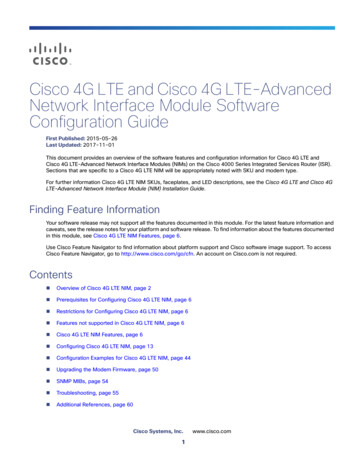
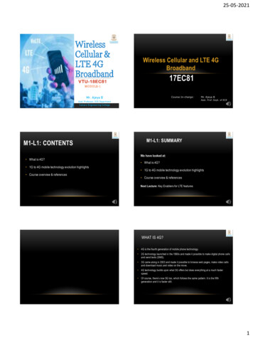
LTE-A plays a critical role in bringing differentiated service to mobile networks and acts as a conduit for monetizing mobile datagrowth. Early LTE adopters who invested in LTE infrastructure like South Korea, Japan, and the United States, the world'smost advanced mobile markets, have seen successful revenue growth and increasing data average-revenue-per-user (ARPU).Furthermore, because LTE provides lower cost-per-bit service, the early adopters achieved better control over operationalexpenses which, in turn, helped improve TCO. The early adopters quickly realized the importance of "first to market" and "bestto market," or phrased another way, "build it and they will come."45Verizon Wireless, SK Telecom, and NTT DoCoMo are good examples where the major wireless service providers investedearly in migrating to LTE. Each has reported data ARPU growth with stable profitability. Conversely in Europe, where wirelessproviders delayed LTE and tried to recoup expensive 3G investments, those providers are experiencing sharp declines in6ARPU. Figure 3 illustrates the contrast between the average revenue per connection (ARPC) and ARPU in the U.S. versusEurope, where consumers in both markets are seeing the benefit of lower cost per connection. However, because U.S.consumers connect with more data-intensive devices, the revenue per subscription is increasing. The ARPU-ARPC gapcoincides with LTE network deployments and mobile ecosystem expansion in the U.S. In fact, in 2013 the two largest U.S.operators spent 21B in CAPEX, more than all 20 operators serving the five largest EU countries. Consequently, to achieverevenue growth and profitability like that seen in the early LTE adopter markets, today the global investment in 4G infrastructureis a major reason why service provider CAPEX will reach 250B in 2017.Figure 3. When mobile users connect with more data-intensive devices, as in the U.S. LTE market, the decline in revenue-perconnection is muted and operators generate higher ARPU. Source of image is GSMA Wireless Intelligence.www.gsma.com/.Improving profitability and generating higher data ARPU are today's catalysts for the new cycle of worldwide investment in mobile7infrastructure. As shown in Figure 4, CAPEX is forecast to grow at 4.7% compounded annual growth rate (CAGR) from 2013 to2020. Generally, the equipment-to-CAPEX ratio is about 33%. Approximately 35% of the 2017 infrastructure equipment8investment is targeted at LTE which is forecast to grow at 16% CAGR from 2012-2017.Page 4 of 13
Figure 4. To sustain data growth, the operator CAPEX investment in mobile networks is forecast to exceed 1.7 trillion (USD) from2012 to 2020. Source of image is GSMA Wireless Intelligence.Figure 5 summarizes the primary market forces driving the evolution of 4G LTE-A and the deployment of new eNodeB equipment.Mobile data traffic and the number of mobile broadband subscribers are growing exponentially. Mobile network performance mustevolve to sustain the increasing demand for bandwidth-hungry applications and this, in turn, requires service-provider CAPEXinvestment in network modernization. The confluence of these forces drives the evolution and adoption of LTE-A.Figure 5. Four primary market forces are driving evolutionary improvements in radio access technology.Rel-12 Trends in Macro Cell Base Station TransmittersMarket drivers, including service provider's CAPEX, are good indicators that the investment in LTE wireless infrastructure willPage 5 of 13
continue out to 2020 and beyond. Much of this investment will focus on building new LTE macro cell networks and transitioning3G macro cells to 4G access. Macro-cell base stations provide excellent wide-area coverage, often over 10s of kilometers(dozens of miles), and serve multiple RF bands spanning 700MHz to 2.6GHz. When needed, they provide backhaul for otherbase stations. As such, macro cells play a critical role in the cellular network and will continue their vital role well into the future.Rel-12 enhancements address ways to help service providers add more macro cell capacity and improve cell-edge performancewhile lowering TCO. Carrier aggregation (DL and UL), AAS, and spatial multiplexing are three Rel-12 features that augmentmacro cell base-station performance.Downlink Carrier AggregationDL-CA groups individual component carriers (CC) together to effectively increase the transmission bandwidth available for mobileusers. Component carriers can be located across the spectrum of LTE bands. DL-CA allows service providers to better utilizefragmented spectrum from 700MHz to 2.6GHz while delivering higher user peak data rates and increasing overall networkcapacity. Rel-10 specified 100MHz of maximum aggregated bandwidth per user, comprising up to five 20MHz component carriers.Initial LTE deployments are limited to aggregated bandwidths up to 40MHz to better serve network operator spectrum assets andallocation scenarios. Typical applications aggregate 5MHz, 10MHz, or 20MHz component carriers in different frequency bands.9There are three types of DL-CA: (1) intraband contiguous, (2) intraband noncontiguous, and (3) interband noncontiguous.Carrier aggregation can be used in FDD or TDD modes, and supports bandwidths of 1.4, 3, 5, 10, 15, and 20MHz. Figure 6summarizes the types of DL-CA, different CA classes, and transmission bandwidth configurations. Different CA combinationsare called out in Rel-10, Rel-11, and Rel-12 for both uplink and downlink. In Rel-12 a new DL combination is being introducedthat aggregates three interband component carriers (3DL-CC). For example, aggregation of LTE bands 1-5-7 was demonstratedby Huawei and LG Uplus at 800MHz (CC 10MHz), 2100MHz (CC 10MHz), and 2600MHz (CC 20MHz) to achieve300Mbps peak throughput.10Figure 6. Illustration summarizes the different types of carrier aggregation, different CA classes, and transmission bandwidthconfigurations.Carrier aggregation is supported across the LTE ecosystem in mobile chipsets from Qualcomm and Sequans with mobile devices in the Samsung S5 and HTC One (M8) smartphones, and base-station equipment from companies like Ericsson,Page 6 of 13
Huawei, and Nokia Networks. Some examples of joint demonstrations with wireless service providers that achieve peak data101112rates of up to 450Mbps include Huawei and LG Uplus, Ericsson and Telestra, Nokia and SKT. Presently DL-CA is close toramping up worldwide in live networks so it will not be long before mobile LTE users enjoy the benefits of higher peak data rates.Active Antenna SystemAAS is the next step of the eNodeB evolution. Cellular base stations have evolved from the conventional base transceiver station(BTS), to remote radio unit (RRU), to integrated antenna radio (IAR), and now to AAS. Figure 7 illustrates the evolutionary pathwhere Generation II moves the radio units from the indoor enclosure at the base of a tower, up to the tower top below theantenna. RRU replaces coaxial feeder cables with fiber-optic cable interconnects. Generation III integrates the radio unit,typically 2T4R, and antenna within the radome where the radio interfaces with a cross-polarized antenna array. And GenerationIV integrates multiple radio transceivers inside the antenna where each radio interfaces with a dedicated antenna element to13form an array. An example is the introduction of Alcatel-Lucent's "cube lightRadio."Figure 7. The evolution of base stations from the first-generation BTS through contemporary Generation IV.Each base-station generation advanced improvements in one or more critical areas: better radio performance, lower operatingpower, reduced size, or faster installation time. For example, the transition from BTS to RRU saw a 50% cut in powerconsumption and 3dB reduction in downlink loss. The transition from RRU to IAR saw a 40% reduction in size, 8% lower power,14and 1dB improvement in downlink loss. The Generation IV AAS achieves yet a new, higher level of performance.AAS is an evolutionary development that will enable macro cells to precisely focus LTE capacity to specific user groups. It willimprove cell-edge performance while also reducing base-station operating power. The potential of AAS base stations lies inelectronic beamforming and spatial processing techniques that produce dynamically adjustable radiation patterns. Figure 8illustrates the AAS structure. An array of RF transceivers and antenna elements allows electronic baseband control of phaseand amplitude to shape and steer the radiated beam. This control enables single-antenna cell sector subdivision. Horizontal(azimuth) and vertical (elevation) control of the beam pattern realizes several important applications: (1) verticalsectorization(2) independent TX-RX tilt, (3) RAT tilt, (4) receiver diversity, and (5) full-dimension MIMO.Page 7 of 13
Figure 8. The structure of an active antenna system (AAS) with embedded RF (left), and AAS beamforming capabilities in amacro cell base station (right).Figure 9 shows examples of the AAS applications that wireless service providers can leverage in macro cell base stations. Withbeamforming and beam steering, AAS macro cells can better utilize radio resources, adapt to changing traffic patterns, andimprove the mobile users' experience. For example, independent TX-RX electronic tilt of the RX and TX beams can be used tooptimize individual UL and DL paths; thus, extend mobile device battery life when the RX-TX link budgets differ. When the ULpath is optimized, the mobile device transmitter's power amplifier can be set at the best possible operating power level withoutwasting battery energy.AAS can bring many benefits to the LTE ecosystem. However, the RF properties of AAS base stations differ from conventionalantenna systems and this must be studied in detail.Page 8 of 13
Figure 9. Several AAS beamforming and beam steering applications are possible for macro cell sites.In Rel-12 a working group is studying AAS. A main objective of the 3GPP active antenna work item is to identify the RFrequirements and conformance testing for AAS base stations. Some of the topics include adjacent-channel leakage ratio15(ACLR), in-band/out-band emissions, receiver sensitivity, receiver blocker performance, and 3D channel modeling. The widelyrecognized benefits of AAS are the primary reasons behind the 3GPP study: capacity gains by employing flexible cell splits withbeam shaping and steering; elimination of cable attenuation and power losses; fewer components mounted on the tower top;and better network availability with transceiver redundancy. The advent of AAS Generation IV base stations promises higherlevels of performance for macro cells and effective delivery of new 4G services like Voice-over-LTE and LTE-Broadcast.Spatial Multiplexing with Downlink MIMOTransporting gigabit-per-second downlink peak data rates in a 100MHz carrier aggregation band-limited system requires spectralefficiency techniques beyond high-order modulation. As wireless communication links approach the limits of Shannon's capacitytheorem, the spatial dimension must be exploited and, hence, spatial multiplexing with multiple antenna configurations must beadopted. LTE Rel-8 saw the inclusion of 2X2 and 4X4 MIMO with 4-layer transmission. Rel-10 extended this to 8X8 downlinkMIMO, also called transmission mode 9 (TM9). Rel-12 explores ways to optimize 8X8 DL MIMO and includes an investigation offull-dimension MIMO (FD-MIMO), complimented by AAS.Adopting spatial multiplexing with 8X8 downlink MIMO can deliver an 8x increase in throughput without using more spectrumbandwidth. In situations where communication link reliability is important or poor signal conditions exist, then downlink spatialdiversity (transmit diversity) might be employed to obtain diversity gain and improve signal-to-interference-plus-noise-ratio(SINR). Important network performance gains can be realized with MIMO spatial multiplexing or MIMO spatial diversity.However, these advanced techniques require multiple antennas at both the eNodeB and the mobile user equipment (UE).Deploying 8x8 MIMO requires eight antennas at the eNodeB and UE, as shown in Figure 10. Because antenna spatialseparation is needed, it will be difficult to integrate eight antennas in a small-form-factor mobile device like a smartphone.16However, 4X4 MIMO is practical with new advancements in antenna development like that seen by SkyCross where 580Mbpspeak data rates have been demonstrated. Larger-form-factor devices like data-hungry tablets and notebook PCs will have aneasier time integrating eight antennas. And because it is more practical and enjoyable to view high-definition (HD) video contenton large-screen devices, tablets and mobile PCs can take full advantage of mobile HD video with high-throughput 8X8 MIMO.Moreover, since mobile video is a leading driver of growth in data traffic and considered a value-added feature for wirelessservice providers, there is an important trend in the macro cell eNodeB to support multiple antennas with four- and eight-layertransmission.Page 9 of 13
Figure 10. Spatial multiplexing with 8X8 MIMO requires eight antennas at both the eNodeB and the mobile user device.Much of the foundation for downlink MIMO was completed in Rel-8 thru Rel-11 sessions. This included the development oftransmission modes 1 thru 9, code book structure, channel state information (CSI) feedback, demodulation reference signal (DMRS), downlink control information (DCI) format, and dynamic switching between SU-MIMO and MU-MIMO. To improve spectralefficiency Rel-12 focuses on two CSI enhancements: (1) 4TX Precoding Matrix Index feedback, and (2) aperiodic feedbackPhysical Uplink Shared-Channel mode3-2. Rel-12 also begins initial studies of FD-MIMO.FD-MIMO unites AAS, 3D beamforming, and spatial multiplexing to deliver efficient spectrum utilization while increasing networkcapacity. The possibilities of FD-MIMO are shown in Figure 11, where antenna beams can be precisely and independentlyfocused on many mobile users at different azimuth and elevation planes. In Rel-10 and Rel-11 the MIMO features specificallyaddressed eNodeB antenna directivity in the azimuth. Rel-12 explores ways to fully utilize the spatial domain.Figure 11. Applications of full-dimension MIMO (FD-MIMO) with 3D beamforming.To realize the FD-MIMO vision, further work is needed in 3D channel modeling, codebook design, feedback enhancements, anddefinitions for AAS radio requirements. Nevertheless, the first step, integrating multiple wideband radio transmitter channels intoPage 10 of 13
a space-constrained antenna system, can be addressed with an innovative bits-to-RF solution. Part 2 of this application notereveals how direct-conversion RF-DAC technology can be embedded in AAS to reduce transmitter operating power, minimizeheat dissipation, and shrink circuit board area.ConclusionThis application note, Part 1 of this two-part series, explored the market forces that are driving global adoption of LTE-Advancedand discussed the evolution of 4G cellular base-station equipment. The application note reviewed 3GPP Rel-12 work items andrelevant technology trends in eNodeB downlink transmitter applications. It explained how Rel-12 enhancements in widebandcarrier aggregation, multilayer spatial multiplexing, and AAS offer many benefits to 4G networks, namely, improvements incoverage, capacity, network utilization, and peak data rates. However, the Rel-12 features introduce new analog integrationchallenges when designing macro cell eNodeB transmitters. To be exact, designers will need to increase transmitter channeldensity and deliver ultra-wideband performance with full carrier frequency agility, bound by the constraints of small size, lesspower, and lower system cost.Part 2 of this application note series introduces a disruptive radio solution that can help engineers shape new RF transmitterarchitectures and overcome Rel-12 analog integration challenges. Part 2 focuses on novel RF DAC technology that yields asingle-chip radio transmitter solution. Readers will learn how RF DAC technology offers radio engineers a way to shrink size by60%, reduce component count by 75%, and lower operating power by 1000mW per channel.References1. Cisco Visual Networking Index – Global Mobile Data Traffic Forecast Update, ite paper c11-520862.html.2. Ericsson Mobility Report, On the Pulse of the Networked Society, June 2014, port-june-2014.pdf.3. Alcatel Lucent Blog, 2013 insights: real proof that 4G speed brings consumers, content and cash, ngs-consumers-content-and-cash.4. Verizon Q2CY14 earnings results, . SK Telecom Q2CY14 earnings results,.6. GSMA Mobile Wireless Performance in the EU and US, May 2013, pages 9-10,www.gsmamobilewirelessperformance.com/ For the report, see http://tinyurl.com/pp8ogf8.7. GSMA, The Mobile Economy Report Series 2014, page 20, www.gsmamobileeconomy.com/. For this report MA Mobile Wireless Performance May2013.pdf.8. Infonetics Research, 2G, 3G, 4G Mobile Infrastructure and Subscribers 4Q12 and 2012, slides 11-12, March tructure-Market-Highlights.asp.9. 3GPP website for more information on CA band combinations and details on Release 12 /68-release-12.10. Huawei and LG Uplus demo 800MHz (10MHz), 2100MHz (10MHz) and 2600MHz (20MHz) achieve 300Mbps peakthroughput, pr.huawei.com/en/news/hw-343675-lg.htm.11. Telestra and Ericsson demo carrier aggregation to combine one 20 MHz block of 1800-MHz spectrum with two 20 MHzcarriers on the 2600-MHz band, 450mbps-lte?section TOP STORIES.12. NSN, KT, SKT achieve world's first TDD-FDD carrier aggregation demonstration, tion-demonstration.13. Alcatel Lucent Maps the Future of Mobile Technology, February 07, 2011, www.alcatel-lucent.com/press/2011/002331.14. 4G Americas, MIMO and Smart Antennas for Mobile Broadband Systems, October 2012,www.4gamericas.org/files/2114/0759/4301/MIMO and Smart Antennas for Mobile Broadband Systems Oct 2012x.pdf.15. 4G Mobile Broadband Evolution, 3GPP Release 11 & Release 12 and Beyond, 4G ers/.16. SkyCross press release, February 24, 2014 -2014-4x4-mimo/.Page 11 of 13
Glossary of Technical Terms2G, 3G, 4GGenerations3GPP3rd Generation Partnership Project4G-LTE4th Generation Long Term EvolutionAASActive Antenna SystemACLRAdjacent-Channel Leakage RatioARPCAverage Revenue Per ConnectionARPUAverage Revenue Per UserBTSBase Transceiver StationCACarrier AggregationCAGRCompounded Annual Growth RateCAPEXCapital ExpenditureCCComponent CarrierCSIChannel State InformationDCIDownlink Control InformationDLDownlinkDL-CADownlink Carrier AggregationDM RSDemodulation Reference SignaleNodeBEvolved Node BFD-MIMOFull-Dimension MIMOIARIntegrated Antenna RadioIMT-AdvancedInternational Mobile Telecommunications-AdvancedITU-RInternational Telecommunication Union Radio SectorLTELong Term EvolutionLTE-ALTE-AdvancedMIMOMultiple Input/Multiple OutRFRadio FrequencyRel-12Release 12ROIPage 12 of 13
ROIReturn On InvestmentRRURemote Radio UnitTCOTotal Cost of OwnershipTM9Transmission Mode 9UEUser Equipment such as smartphonesULUplinkA similar version of this article appeared March 6, 2015 in EDN.Also seeHigh-Speed DACsHTC One (M8) is a registered trademark of HTC Corporation.RF to Bits is a registered trademark and registered service mark of Maxim Integrated Products, Inc.Samsung is a registered trademark of Samsung Electronics Co., Ltd.Related PartsMAX586816-Bit, 5Gsps Interpolating and Modulating RF DACMAX586916-Bit, 5.9Gsps Interpolating and Modulating RF DAC with JESD204BInterfaceFree SamplesMore InformationFor Technical Support: https://www.maximintegrated.com/en/supportFor Samples: https://www.maximintegrated.com/en/samplesOther Questions and Comments: ion Note 6062: ON NOTE 6062, AN6062, AN 6062, APP6062, Appnote6062, Appnote 6062 2014 Maxim Integrated Products, Inc.The content on this webpage is protected by copyright laws of the United States and of foreign countries. For requests to copy thiscontent, contact us.Additional Legal Notices: https://www.maximintegrated.com/en/legalPage 13 of 13
In Rel-10 the 3GPP introduced LTE-Advanced as "true 4G" service to meet or exceed the IMT-Advanced requirements. LTE-A Rel-10 was the next step in the mobile broadband evolution and further expanded on LTE's basic feature set. Presently, Rel-12 is close to introduction with a functional freeze date planned for March 2015.