Transcription
Solutions for Mixed-Signal SoC VerificationNew techniques that are making advanced SoC verification possibleBy Kishore Karnane and Sathishkumar Balasubramanian, Cadence Design SystemsPerforming full-chip verification of large mixed-signal systems on chip (SoCs) is an increasinglydaunting task. As complexity grows and process nodes shrink, it’s no longer adequate to bolttogether analog or digital “black boxes” that are presumed to be pre-verified. Complex analog/digital interactions can create functional errors, which delay tapeouts and lead to costly siliconre-spins. Cadence helps customers overcome these challenges with a fully integrated mixed-signalverification solution that spans basic mixed-signal simulation to comprehensive, metric-drivenmixed-signal verification.IntroductionContentsIntroduction. 1Mixed-SignalVerification Use Models. 2Mixed-SignalVerification Challenges. 3Mixed-Signal Block andIC-Level Verification. 3Real Number Modelingfor SoC Verification. 6Conclusion. 8Mixed-signal applications are among the fastest growing market segments inthe electronics and semiconductor industry. From watching mobile digital TVto reading on your tablet to auto-piloted cars, consumers expect electronics todo more—in more places—than ever before. Driven by growth opportunities inmobile communication, networking, power management, automotive, medical,imaging, and security applications, many silicon vendors are refocusing theirbusiness on RF, high-performance analog and mixed-signal designs.Due to this trend, most systems-on-chip (SoCs) today are mixed-signal, andall SoCs will be mixed-signal at advanced process nodes in the near future. Asprocess nodes shrink and the demand for integration grows, SoC designersare adding more analog circuitry and importing large blocks of mixed-signalintellectual property (IP). This escalating complexity poses severe challengesfor mixed-signal SoC verification, such as incomplete SoC-level and systemlevel verification or uncertainties in verification coverage.Things were simpler in the past, when mixed-signal SoCs contained IP blocksthat were designed separately and then bolted together during systemintegration. Designers simply brought a handful of “black boxes”—blocks ofanalog circuitry that were presumed to be pre-verified—into a mostly digitalSoC design. Now, however, analog IP blocks are not only growing morenumerous and complex, but also increasingly contain digital control logic.Additionally, today’s mixed-signal SoCs typically contain multiple feedbackloops and exhibit complex interactions between the analog and digitalcircuitries. As a result, teams cannot fully verify these highly integrated SoCsusing a traditional black-box approach.According to industry estimates, more than 60 percent of SoC design re-spinsat 45 nanometers and below are due to mixed-signal errors. A re-spin maycost an extra 5 to 10 million dollars and an 8 to 10 week delay in a productrollout, with potentially disastrous consequences. Many re-spins are due to
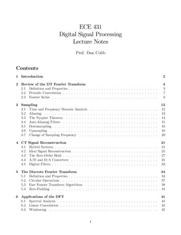
Solutions for Mixed-Signal SoC Verificationcommonplace, avoidable errors such as inverted or disconnected signals. To avoid these errors, mixed-signal SoCteams need to implement verification methodologies that can quickly scale and accurately validate the interfacesbetween analog and digital domains.Additionally, top-level mixed-signal SoC verification is challenging because it encompasses both analog and digitalIP blocks at different levels of abstraction. The blocks could be represented in schematics, SPICE netlists, analogbehavioral models, or purely digital models. This makes it essential to have a hierarchical verification approach—one that supports different levels of abstraction and different simulation engines and modeling languages.This paper presents solutions for tackling today’s mixed-signal verification challenges. After discussing commonverification challenges, it looks at mixed-signal block and integrated circuit (IC)-level verification methodologiesusing analog behavioral modeling and combined analog and digital solvers. It then describes the use of realnumbers for modeling analog functionally and using them in top-level SoC verification.Other mixed-signal white papers from Cadence discuss overall mixed-signal design challenges and mixed-signalimplementation.Mixed-Signal Verification Use ModelsTraditionally, verification use models were different among the analog and the digital domain, and did not have anydependencies among them.Digital-centric users verify ICs primarily constructed of digital logic developed with a standard cell methodology.Analog blocks that support specific functions and protocols are integrated by importing hard analog IP. These aretraditionally black boxes that provide no visibility into the IP. This is sometimes called a “big D, little A” or “digitalon-top” methodology. In this type of design methodology, verification was focused on the digital side using a puredigital simulation flow.Analog-centric users import digital logic blocks into analog, custom digital, or RF circuits. The digital blocks mayprovide control, calibration, or connectivity functions. This is sometimes called a “big A, little D” or “analog-ontop” methodology. In this type of implementation methodology, verification is done using traditional SPICEsimulations.With today’s complex mixed-signal SoCs, users need to run full-chip verification that covers all possible analog/digital interactions. The SoCs may have many analog blocks, along with some mixed-signal blocks that could havebeen entire chips in previous process generations. As such, a black-box approach (which provides no visibility intosignals and assumes blocks have been completely pre-verified) is no longer oryPLLTraditional Mixed-signal DesignPhysical hierarchy separatesdigital and analogVideoBBRFModern Mixed-signal DesignDigital and analog distributedthroughout designFigure 1: Increasing complexity of mixed-signal designsKey features required for complex SoC verification include: Block importation with full visibility into signals and design details, allowing users to debug the block if errorsemerge The ability to model discrete real data in an all-digital simulation Integrated analog/digital debuggingwww.cadence.com2
Solutions for Mixed-Signal SoC Verification Support for modeling and simulation at various levels of abstraction, including SPICE, analog behavioralmodeling, and digital HDLs An understanding of the impact of low-power design techniques—such as power shutoff—on both analog anddigital IP Single-kernel integration of analog and digital solvers Verification planning, testbench automation, and coverage metrics applicable to the entire mixed-signal SoC Support for verification reuse and verification IP Fast mixed-signal regression runsMixed-Signal Verification ChallengesIn all types of IC design, the verification task is growing exponentially as complexity increases. For digital ICs,functional verification now takes up 70 percent of the logic design phase. Add analog and mixed-signal IP, and thattask gets even more complex. Even in digital verification environments, simulation is never fast enough. Yet digitalRTL simulation is orders of magnitude faster than SPICE-based analog simulation.Analog and digital simulations use fundamentally different paradigms. While digital simulators solve logical expressions sequentially by triggering events, analog simulators must solve the entire analog system matrix at every timestep. Each element in the analog design can have an instantaneous influence on any other element in the matrix.There is no obvious signal flow in any direction, and time is continuous rather than discrete.The analog verification methodology is traditionally ad-hoc by nature, lacking the formalized methodologythat is available on the digital side. Digital verification teams now have access to executable verification plans,constrained-random stimulus generation, testbench automation, assertions, and coverage metrics. In digitaldesign, the metric-driven verification approach—standardized for reusability as the Universal VerificationMethodology (UVM) —helps engineers build confidence in the verification by increasing coverage to a desiredlevel. On the analog side, verification is driven by directed tests run over sweeps, corners, and Monte Carloanalysis. Several analog solvers today provide low-level device checks, but there is little or no support forverification planning or coverage metrics.As noted previously, many silicon re-spins stem from mixed-signal verification issues. Customer experienceshows that many design failures are caused by what some might call “highly embarrassing” errors, including pinconnection errors, inverted polarity, incorrect bus order, or pins connected to the wrong power domains. In theabsence of simple checks, such errors are often found only in lengthy analog simulation runs, if they are found atall.Advanced low-power techniques are introducing new complications to mixed-signal verification. For example,consider a digital control logic circuit that feeds into an analog block. If the power is shut off in the digitalcircuit, the simulator will model data corruption internal to the power domain by setting all the internal valuesto Xs (unknowns). If the simulator does not understand the impact on the analog block, it may be difficult todetermine whether the X states derive from the shutoff or from a functional failure.Mixed-Signal Block and IC-Level VerificationVerification of a mixed-signal SoC involves many different levels of abstraction. In general, transistor-levelsimulation with SPICE remains the gold standard for analog IP verification. While it provides very high accuracy,SPICE is much too slow for chip-level simulations, unless it is used extremely selectively.Analog behavioral modelingTo achieve reasonable simulation speeds, many mixed-signal teams employ analog behavioral modeling. Thisapproach can be 5 to 100 times faster than SPICE. The actual speedup varies widely depending on the applicationand the level of detail in the model. Analog behavioral models are typically written in one of the following languages: Verilog-AMS: a mixed-signal modeling language based on IEEE 1364 Verilog that can define both analog anddigital behavior, providing both continuous-time and event-driven modeling semantics Verilog-A: the continuous time subset of Verilog-AMS, aimed at analog designwww.cadence.com3
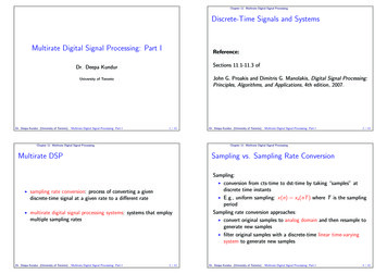
Solutions for Mixed-Signal SoC Verification VHDL-AMS: similar in concept to Verilog-AMS, this language provides analog and mixed-signal extensions to IEEE1076 VHDL SystemVerilog: this language is being extended to support aspects of analog behavior required for SoC verification in an effort also known as SV-DC[x]The creation of analog behavioral models can be challenging. Analog designers are in the best position to createthese models, since they are familiar with their own circuits. But many analog designers lack the programming skillsor knowledge required to construct behavioral models, and few are familiar with Verilog or VHDL. Digital designershave that familiarity, but know less about the analog circuits.Figure 2 shows the tradeoff between simulation accuracy and performance among SPICE, FastSPICE, analog behavioral models (Verilog-A/AMS or VHDL-AMS), real number models, and pure digital simulation. These numbers aregeneric and can vary significantly for different applications. Note the wide range of accuracy and performance thatis possible for Verilog-AMS and VHDL-AMS behavioral models. Pure digital simulation can only represent an analogsignal as a single logic value, but this may be sufficient for connectivity checks in mixed-signal SoCs.Modeling -AVerilog-AMSVHDL-AMSReal number models arethe most effective way toabstract AMS functioinalityfor full chip simulationReal Number Model (RNM)Pure DigitalSimulation Performance / CapacityFigure 2: Model accuracy vs. performance gain for mixed-signal simulationAnother important factor is the effort required to set up a simulation and create the model. While SPICE simulations run slowly, they are relatively easy to set up. The time required to create a high-quality analog behavioralmodel, however, can range from hours to days or even weeks. Real number modeling is restricted to a signalflow approach; analog convergence is less of an issue. Typically, it takes less modeling efforts to develop realnumber models than traditional analog behavioral model.The modeling goals of analog behavioral models may differ. A performance model needs to precisely capturecritical circuit behavior. Functional models capture circuit behavior only to the level of detail that is needed to verifythe correct design functionality.Analog-centric verification use modelCo-simulation between analog and digital solvers is one methodology that has been used for mixed-signal blockand chip verification. Nonetheless, traditional co-simulation approaches have been plagued with limitations. Earlyco-simulation environments, for example, typically employed Verilog and SPICE operating in separate simulationkernels linked through inter-process communications (IPC). This made it difficult to keep analog and digitalsimulation engines in lockstep. Users typically had to partition the circuit, deal with two netlists, and cope with twodisparate debugging environments.Advanced mixed-signal verification solutions such as the Cadence Virtuoso AMS Designer Simulator canachieve better performance than traditional co-simulation solutions. These products utilize a single, executablekernel for both analog and digital simulation engines. These solutions also provide extensive language andmodeling support. They support behavioral models in Verilog-A, Verilog-AMS, VHDL-AMS, and emergingSystemVerilog-DC; transistor-level analog circuit models; and digital languages such as Verilog, VHDL, SystemC , e,and SystemVerilog-DC.www.cadence.com4
Solutions for Mixed-Signal SoC VerificationAnalog DomainMixed Signal VerificationDigital DomainTransistor levelSchematicGenerate RNMModelRealGenerate Verilog-AMSModelDDDDDDe or SV TestbenchValidate Models toCircuit specs High performance, real number modeling for mixed signal verification Models are easily ported between Virtuoso and Incisive environments Run full-chip verification regression suites at digital speedsBenefits: Increased Predictability, Productivity and Quality (PPQ)Figure 3: Analog-centric verification use modelFor example, Virtuoso AMS Designer Simulator links the Virtuoso custom design platform with the CadenceIncisive (digital) verification platform. It provides an integrated GUI, integrated embedded simulation engines, anda common verification methodology (Figure 4). It also supports simulation engines including Virtuoso Spectre Circuit Simulator, Virtuoso UltraSim Full-Chip Simulator, Virtuoso Accelerated Parallel Simulator, Virtuoso Spectre RFSimulation Option, and Incisive Enterprise Simulator.Mixed-signal IP, ICVirtuoso platformIntegrated GUIMixed-signal SoCIncisive platformIntegrated simulation enginesAnalogdesignerCommon verification methodologyVerificationengineerFigure 4: Example of well-defined mixed-signal verification solutionKey features of a robust analog-centric mixed-signal verification solutionConnect modules: Digital simulators traditionally understand only 0, 1, X, and Z, while analog simulators workwith continuous values. Connect modules are used to translate digital signals to and from analog voltage levels.These bi-directional “connect” modules are inserted automatically to increase efficiency in an ideal mixed-signalverification solution.Power-smart connect modules: In an advanced low-power verification scenario, a “power-smart connectmodule” allows the Common Power Format (CPF), which defines digital low-power structures, to be leveraged in amixed-signal simulation. If an analog signal’s source can be traced to a digital signal that has a CPF definition, thenwe can automatically insert a power-smart connect module that can distinguish between an X resulting from afunctional error and an X resulting from power shutoff, nominal conditions, or power modes.Efficient data flow interaction: Another key feature is the ability for users to efficiently interchange differentlevels of abstraction, allowing the design to change over time from full behavioral to full transistor level.Real number modeling: Support for real number modeling (RNM) in verification platforms allows the simulationof discrete, floating-point real numbers that can represent voltage levels. RNM enables users to describe an analogblock as a signal flow model, and then simulate it in a digital solver at near-digital simulation speeds. For analogand mixed-signal block verification, RNM can be used to speed high-frequency portions of the analog signalwww.cadence.com5
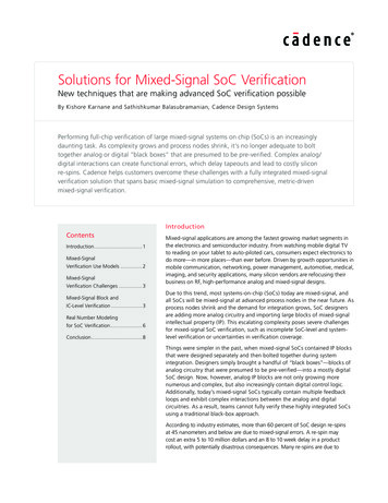
Solutions for Mixed-Signal SoC Verificationpath—which take the longest to verify in simulation—while DC bias and low-frequency portions remain in SPICE.But the greatest advantage of RNM is in top-level SoC verification, where engineers can represent all electricalsignals as RNM equivalents and stay within the digital simulation al-Centric MethodologyIncisive Use ModelVerilogUnifiedsimulationand debugAnalogReal NumberModelAnalog-Centric MethodologyVirtuoso Use ModelVerilogSpiceVerilogA/(MS)ViVaVirtuoso ADETest benchFigure 5: Range of simulation methodologies forboth analog-centric and digital-centric use modelsReal Number Modeling for SoC VerificationReal number modeling (RNM) models analog block operation as discrete real data. The models are based on signalflow and, hence, can be structured as event-driven.The most obvious advantage of using RNM for top-level SoC verification is that it runs nearly as fast as pure digitalsimulation, which is an order of magnitude faster than SPICE-based simulation or even analog behavioral modeling.This makes full-chip verification possible for large mixed-signal SoCs. Digital simulation speeds permit nightly, highvolume regression tests. With no analog engines, there are no concerns about convergence errors.Language support for real and wrealMany languages support RNM including Verilog, SystemVerilog, VHDL, e, and Verilog-AMS. The first four supporta real data type, while Verilog-AMS supports wire-real, or wreal. Figure 6 shows what capabilities each languagesupports. (“Disciplines” differentiate domains, such as power domains, in Verilog-AMS).Verilog realSystem-Verilog DC(Under Development) Module internal usage of realvariables User defined types No real value ports (requires real2bits/bits2real) Definition of a net type based on itsconnectivity No support for X/Z state No multiple wreal driverVHDL real User Defined Resolutioin FunctionsVerilog-AMS wreal Easy interaction with analog Real valued ports Direct connection to electrical netsusing E2R and R2E connect modules Resolution function Disciplines association Multiple drivers Multiple wreal driver support User-defined types Ability for scope-based wrealresolution function specification Limited connection to analogSpecman/e real Mainly for testbenching Identification of highimpedance/unknown state (X/Zsupport) Random generation, coverage,checking Direct access to analog values(receive/drive)Figure 6: Language support for real number modelingwww.cadence.com6
Solutions for Mixed-Signal SoC VerificationWreal is a native Verilog-AMS language feature that brings the benefits of digital signals into Verilog-AMS,including the capabilities listed in Figure 6. For example, wreal allows real variables on ports. The VHDL real datatype provides similar advantages. Compared to VHDL real, Verilog-AMS wreal is more advanced in the area ofconnect modules, while VHDL real is slightly more flexible in terms of resolution function and user-defined types.The e language supports RNM as well as coverage constructs. This offers a direct interface to access and driveanalog values to and from e.Figure 7 shows an example wreal model of a voltage-controlled oscillator (VCO).module vco(vin, clk);input vin; wreal vin;output clk;reg clk;real freq,clk delay;always @(vin) beginfreq center freq vco gain*vin;clk delay 1.0/(2*freq);andalways #(clk delay) clk !clk;endmoduleFigure 7: VCO model using Verilog-AMS wrealRNM is not, however, a replacement for analog simulation. It is not appropriate for low-level interactions involvingcontinuous-time feedback or low-level RC coupling effects. Nor is it intended for systems that are highly sensitiveto nonlinear input/output impedance interactions. And, real-to-electrical conversions require some careful consideration. If one is too conservative, there will be a large number of time points. If one is too liberal, there can be aloss of signal accuracy.Metric-driven verificationAnother advantage of staying within the digital simulation environment is the availability of a metric-driven verification (MDV) methodology. MDV makes it possible to use specifications to create verification plans, measureprogress, and more easily determine when the verification process is complete. Functional and code coverage, checks,and assertions provide the verification metrics used to determine closure. Information from verification job failures,bugs, and design revisions provides insight into the status of a project.The MDV flow starts with automated planning. The plan specifies the verification environment requirements for acoverage-driven testbench language, such as SystemVerilog or e. Verification IP provides immediate access to theMDV methodology by delivering a protocol-specific verification plan and test suite. Progress reports help the verification team make adjustments to their resource allocations in people and tools, making it possible to reach closuremore efficiently and measure closure more accurately.www.cadence.com7
Solutions for Mixed-Signal SoC mationMetricsanalysisFigure 8: Metric-driven verification management flowWith SystemVerilog and e functional coverage capabilities, MDV permits an advanced coverage-based verificationand debug methodology to reach verification closure quickly. This metric-driven methodology is currently employedmainly by digital engineers, but since the majority of the SoCs today are mixed-signal, more and more verificationengineers are looking to adopt this approach for mixed-signal SoCs. The mixed-signal MDV flow takes advantageof RNM to enable customers to perform top-level SoC verification.Digital mixed-signal simulation permits real number models to run natively in a pure digital environment. Userscan run full-chip verification with digital solvers for functional simulation and interconnect verification. Whenmore accuracy is needed, users can still run transistor-level simulation or analog behavioral models in the sameenvironment. Real number models are portable between digital (Incisive) and analog (Virtuoso) design environments. For example, a model can be developed and validated for an AMS block in the Virtuoso environment andbe used during SoC verification in the Incisive environment.In recent years, tools are emerging for automating the process of model generation and validation. For example,the Cadence Virtuoso Analog Design Environment provides Schematic Model Generation and AMS Design ModelValidation.There are also best practices for writing and validating real number models, many of which are described inthe Mixed-Signal Methodology Guide: Advanced Methodology for AMS IP and SoC Design, Verification, andImplementation.Verification of real number models is essential. In most cases, the original transistor-level representation is used asa reference implementation. To verify the model against the reference, engineers run the same simulation on bothand compare the results. Simulation setups and testbenches should be available from the block-level verificationflow. Comparisons can be done manually, or highly automated for regression testing.ConclusionFull-chip verification of large mixed-signal SoCs is a daunting task. As complexity grows, it is no longer sufficientto bolt together pre-verified analog or digital “black boxes” and hope for the best. Complex interactions betweenanalog and digital domains are resulting in more and more functional errors, which in turn are causing delayedtapeouts and silicon re-spins that may cost millions of dollars.Fortunately, there are solutions. A wide range of modeling and simulation approaches are available for analog anddigital circuits. SPICE-based simulators are still needed for verifying individual analog IP blocks. When it is time tomove up to the subsystem or chip level, analog behavioral models can provide up to a 100x performance increase.www.cadence.com8
Solutions for Mixed-Signal SoC VerificationWhile traditional co-simulation solutions link separate analog and digital kernels, the next-generation mixed-signalverification solution should provide single-kernel execution for a variety of analog and digital solvers. It should alsosupport a number of modeling languages, including VHDL-AMS and Verilog-AMS. Automatic insertion of “connectmodules” to translate between digital and analog signals is a must.For top-level SoC verification, engineers can convert analog models into real number models. This makes it possibleto stay completely within the digital simulation environment, taking advantage of metric-driven verificationfeatures such as verification planning, random test generation, coverage, and assertions. It also allows near-digitalsimulation speeds. Real number modeling with expanded support for the Verilog-AMS wreal data type will furtherreduce the verification cycle time.Thus, only a fully integrated mixed-signal verification solution—one that spans basic mixed-signal simulationto comprehensive, metric-driven mixed-signal verification—forms the foundation for a successful and efficientmethodology to develop today’s advanced mixed-signal SoCs.Cadence is transforming the global electronics industry through a vision called EDA360.With an application-driven approach to design, our software, hardware, IP, and services helpcustomers realize silicon, SoCs, and complete systems efficiently and profitably. www.cadence.com 2012 Cadence Design Systems, Inc. All rights reserved. Cadence, the Cadence logo, Incisive, Spectre, and Virtuoso are registered trademarks ofCadence Design Systems, Inc. SystemC is a trademark of the Open SystemC Initiative Inc. in the US and other countries and is used with permission.All others are properties of their respective holders.22941 08/12 MK/LX/PDF
between analog and digital domains. Additionally, top-level mixed-signal SoC verification is challenging because it encompasses both analog and digital IP blocks at different levels of abstraction. The blocks could be represented in schematics, SPICE netlists, analog behavioral models, or purely digital models.