Transcription
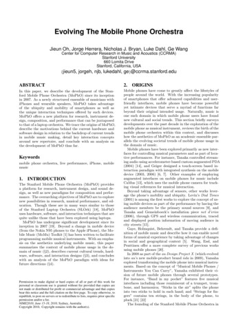
N95- 28752TUNEDGRIDGENERATIONArmin WulfICEMWITHand VedatCFDBerkeley,ICEMCFDAkdagEngineeringCA 94704ABSTRACTICEMCFDis a CAD basedtured, unstructuredefforts haveunstructurederationmaticpackageand unstructuredthat opmentbeen spent to extend ICEM CFD's multiblockstructuredand hexahedralgrid generationcapabilities.The modules added are: a parametricgrid gen-moduleversionobjectsgrid generationtetrahedraland a semi-automaticof the hexahedralin rectilinearthe procedureshexahedralgrid generationgrid generationenclosuresmodulehas been developed.used will be described,Theseand examplesmodule.for aroundA fullyauto-a set of predefinedmoduleswill be presentedandwill be discussed.INTRODUCTIONThe abilityto accuratelytions is becominggridscreate a computationalincreasinglycan be employedtools for creatingimportantto treat complexgeometriesgrid aboutin the analysisgeometricor importingExistingmethodserationgeometryfrom variousare generallyin orderfor overICEMCFD computationalCFD embodiesCADsystems.25 differentconfigurafull CADComputationalCFDflow solversgrid genlitverytime consuming.Current codesalso require high level of userexpertiseWithICEMcomplexfor , includingboundaryconditionscan be generatedand structuralanalysis codes 1. (Figure1).structuredgeometricallyto achieveGEOMETRYANALYSISCODESopti-mal usage. Since the rapid constructionof suitable multiblockstructuredcomputationalstill one of the pacingCFDapplications,tionalityCFD.additionalhas beenTheygrids isissuesaddedare ICEMinfunc-to ICEMCOMAKforparametricmulti-blockmesh generation and ICEM HEXA for semiautomaticgeneration.hexahedralIn addition,Figuremeshthe fully automatichexahedralI:Positioningof lCEMgeometr3, andanalysisgrid generationCFDbetweencodes.modulecalledtheICE-PAK will be presented.ICEPAKhas been developedInternational(fdi) 2 to support thermal managementin coorporationwith Fluid Dynamicsof electronicenclosures.For ICEPAKfully automaticrestricted.the geometrygrid generationis possible,because477representationis
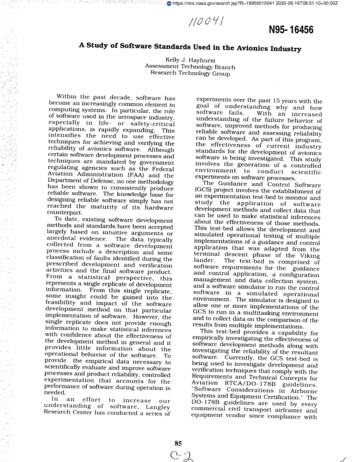
PARAMETRICICEMCOMAKICEMCFD'susingCOMAKto get a meshGRIDis a parametricstructuredGENERATIONmulti-blockgrid generation(COnfigurationof the sametopologygrid CEMCOMAKtool whichis an extendedof a givenconfigurationthe meshit is possiblewith geometric. USINGto replaydifferences.the constructionIt offersoptionis created,processtwo modes;ofin orderthe Specifica-Geometrywith anySystemJdefinitionof aSurfaceGeometryconfigurationInitial StepI-I Parametric Grid GenerationREAD NEWSURFACE OBJECTSCreateObjectsSurface .of BL OCK DECOMPOSITIONAUTOMATIC REGENERATIONDecompositionDefine Block]Q:CommendSaveEdit File ]WITHGENERATEBOUNDARYMESHCONDITIONStl,Generate MESHwith BoundaryFigureConditions2: Structuref'ICEMCOMA478K, the parametricgridgenerator
tion Modeand the Replayhim to interactivelyare storedobjectent. The boundaryefficientIn Figuretradeor Pro-EngineerusingDuringthe initialinput in IGESthe user has a set of toolsMode,geometricwhenentities.the user wantsit is only necessaryto breakallowingThe user'sto createthe objectactionsa mesharoundgeometryintoare set-upautomatically.of ICEMCOMAKfrom Parametrica parametricfeaturesallowone to performveryis shown.TechnologyCADsystemsCorporationsuchas I/EMSInte-are modelersfromthat can createapproach.step or the specificationformatThesestudies.2, the structuregeometriestopology,Modeand manageThen the user can replay the commandsto create the new multi-blockstructo the new CAD geometry,where sets of geometricalentities can be differ-conditionsgeometricgroupfile. In the Replaywith the sameparts like the original.tured mesh associatedIn the Specificationmanipulate,into a commanda differentgraphMode.create,to the ICEMmode,COMAKthe geometryenvironment.from the user'sCADsystemThe first step is to put surfacesisintoobject groups. The user then composesthe computationalblock structure.During this operationthe session commandsare recordedin a commandfile. The file created is saved. After the pointsalongblockedgesare distributed,the analysis are also createdformat of choice.To performthe parametricwith geometricdifferences,the computationalduringthis session.meshcalculationgrid is created.The boundaryUser then translatesthe meshfor a similargeometryand namesthe objectsthe user goes backconditionsforinto the flow solverwith the samein the newtopologygeometrybutwiththe same object names. After the new IGES file is created, the ICEM Manager grabs this IGESfile and writes the CAD data into the object databaseand initiates ICEM COMAK.COMAKreadsthe new objectcomputationalmat. The replaybatchmodemodeManagerregenerateswith the new geometrycan be treatedon modifiedThe ICEMgraphicalfiles and automaticallytopologythe computationaland translatesas a continuousthe meshgrid by updatingtheinto the flow solverfor-loop for computationalgrid generationingeometries.is writtenuser interfacein TCL/TKapplications.3 a programmingsystemIt is an easy to use scriptingfor developinglanguageand usingfor controllingandextendingapplications.The followingsample script illustratesthe executionof a series of commands in the ICEM Managerto support the automaticreplay modeasit is describedabove. In thisexampleit createsan input for the structuralshowsto run a complexanalysiscodeANSYStems, Inc.# This script# The actions# 1. Translates# andthehowit performsare:two IGES files intoIGES files areknownDDNon each# objects.# 3, Run a Comakto automatically# To makeanscriptANSYSthis script# -/,iceman initparts,fromThe nameswithintheof thesepartspart.whichextractsgeneratea set of winglinefile:## if [file existsusermanager.beforehand.# 2 Run a GPL program# 4. Writecommandappscript,tcl]( sourceuserappscript.tcl}479in yourfromSwansonAnalysisSys-
## The rest of this file is theIt shouldbein thecontentsdirectoryof customyouproc user app script{what} (global env ddn pathconfnameputpathglobal partnames2u pathparts/*ansys out-objects.unselect partcatch (exec/bin/rmobjects/ confname/ geoname/*)directory\directoryd 1foreach if (glob iges/*) [# Convert the part to tGES.set dn (file tail (file rootnameSill]set command- env(ICEM ACN)/iges/iges posti iges/ pfo parts/ dnI iges tist togit yes d directive tmp"runcom commandtges listif [string match *name" Sdn] { lappendnames dn }file that runs the GPL programname dn\update partlistif [( what "all") I I ( what "output")}{# Convert the structureddomains into an unstructuredset dams (glob mulcad/ confname/ geoname/domains/*]set topoflte mulcad/ confname/topology/topo mulcad outset outfile place/domains/struct mergeruncom " s2u path -t topoflle -o ouffile doms"and then exits.# Now run the ansys converter.set topofilemulcad/ confname/ geoname/bocoset ansys mulcad/ confname/ geoname/transfer/ANSYSruncom " ansys output path-dam outfile -b bocofile partname\"sn:linfomsg\"" 0 0makemenumake entrymake entrymakeentrymake entry}k 1# Clear out the old domains.set dams [glob -nocomplainmulcad/ confname/ geoname/domains/"]if (Sdoms ! ""} {eval exec/bin/rm-f doms )}typein to Mulcad"Doneto performare the commandsthe indicatedone. ansys"with conversion."# These lines create# Now move all the parbs to the Comak directory.foreach pf [glob parts/") [if (string match *name* pf) continueexec/bin/cpSpf objects/ confname/ geoname# user would*)}}}d 1if0 {if {( what "all") I I ( what : "comak")}{set extras ""# Now run the Comak job. These key sequencesthe5 extras]}}update partlist"ICEM 3.1 GRAPHICS"#1.I.12.].)set extras {I 6 5.2.).) I.) Y 10,3 Y Y n ) 11.2. I. 12,),5.3}app mulcad extrasset restart [open .restart.trapw]puts restart "F.5.13.5.3. [pwd]"puts restart "F.513.3kim1 gpt"puts restart "F.4.7.y"close restart}pn:\"]}if {( what "all") II ( what : "comak")}(unselect partcatch {exec/bin/rm-f (glob mulcad/ confname/ geoname/parts/testlupdate partlistm 1set partnameTEST1set sheetnametd 1foreach pf Snames{# Run the GPL program.set part partfileparts/ pfif { partname "'} { error "No part"set command" ddnpath db partsi .restart.tmp(get ddn defaults]"runxcom USER APP GPL commandmulcad/ confname/ geoname/parts/testl}))a DDN command-f [globset key (send keyboard eventsapp mulcadexec/bin/rm-f Skey# Convert all the parts in the iges directoryto DDN parts.# If any of them have "name*in their fllename,run them through# the gpl program.set names ""# MakeSxx 0]updatepartltst m 1set partnameTEST1set sheetname1# Set up the IGES directivefile,exec/bin/echo*CONVERT, NAME directive trapexec/bin/echo"define,CREATE310 PART I directive trapupdate partlistextras 0index})update partlist)}{if (Spi "') {eval exec/bin/tin-f Sp parts/.ddnobjects/ confname/Sgeoname/.ddn52]]Run the key.cmd file. }nnnDon'tmodify parameters.))yExit comak. }03yy)Updatetopology.}1253yMesh generation.})))Back to the top. }96yExit mulcad}appendif {( what "all*) II ( what "prepare")}(# First remove all the existing DDN parts and the Comakset p [glob -nocomplain{({({{[whichthatactions480a new menuuser appuser appuser appuser appuser appand add the above"USER Application""Whole script ."Prepare objects ."Run Comak ."Write output .commandto the menu""user app scriptall .user app scriptprepareuser app scriptcomak .user app scriptoutput .
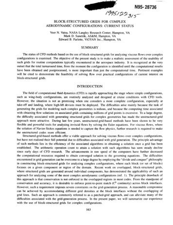
Figure3 illustratesthe applicationof ICEM COMAK to full airplanevolumegrid configurations4.Usingthe specificationmodethe volumegrid is calculatedfor theA320 aircraft.The commandfile is replayedtocreatethe similargrid for theA330 aircraft.Noticethe differencesin the sizesoftheengineandthe fuselagealsothedistancesof the pylon from the fuselageaswell asthe impacton the createdgrids.A320 Grid Using Specification ModeFigure3: Using ICEMCOMAK,generationof grid forSEMI-AUTOMATICICEM HEXAblock ckstructurea volumeor, alternatively,Blocksor externalICEMcanwith completeof the underlyingCADany other CADreolithography)The followingmulti-initial-to the underby the systemindependencefrom the orientationof the patchesis an examplein FigureusingIGESor other translatorsurfacemeshescontrolbound-formats.in PATRANtrimmed NURB surfaceCAD tool or translatedSurfaceformatmeshesin STL (Ste-can also be inputas a sur-generation.of the grid generation4. This configurationand controllingand patchgeometry.or triangularfor meshcal port for chemicalfor inspectionsystemformatface representationtank as shownadjustedbe generatedInput to ICEM HEXA is CAD geometry,in the form of NURB surfaces,and NURB curves. CAD geometryis either created using ICEM CFD'sfromfor creatingwill automaticallycan be interactivelyO-GridsHEXAmesherHEXAand automaticMesh sizes can be defined on the object surfaces or individuallyon the edges usingoptions. The grid is projectedonto the underlyingCAD geometrywith minimumuser interaction,ariesthe initialgeometry.automatically.edge meshingGRIDcomputationalvolumegrid for A320the A330 (Courtesyof Aerospatiale).is an object based semi-automatedmeshes or unstructuredhexahedralThe user can defineize the blockA330 Grid Using Specification Modeand two petrudingthe chemicalprocesscontainscylindersprocessfor a generican inlet, an exhausttakingto the tank.placeinsideThesechemicalport,cylindersthe tank.processinganotherEachcylindri-are utilizedof thesecylindersare connectedto a smaller cylinderswhich they connect to pressureregulators.Sincethis configurationcontains many cylinder T-connections,it producesa moderatelycomplex blockdecompositionstrategyfor any grid generationsystem.481
Control portExhaustportControl portTankInle/Figure 4." The chemicalprocessingtankFigure 5." Block decompositionThesystemNexttheusedfor gridverticesareautomaticallyblocksgenerationfit to thecan be associatedverticestheinitialareare movedfit, blockssplitaregeometryto ngalsoAfterselected.withinteractivetakenthe curves.are splitthefromTheto providestrategyas tructureovertheTheAfterthatblockedgeswillareasin Figuresuchbeedgesof theandblocksthe associationis shownthe critical5.blocksof blocks,manipulation.the CADblockingin Figureis done,6. Afteras thecontrol
Afterthe initialblocksfit,are split furtherto provide control overthe areas such as theipressure ports. The system starts to build inter-aZzZZIiJnal indexblockscontrolfor theas the split oper zation takes place. Blockindices can be used tocontrolwhichthe blockingpart ofare visi-ble. Additionally,thoseonlyparts of the block-ing which are currentlyvisible are split duringthe splittingFigureblockingoperations.7 illustratesstrategies.Figurethe blockingstructureThe user may selectof analysis to be performed.surface geometry.Also seen6: Blockbeingedges of the innerfit to the curves.created.a strategyin FigureblockThis is only one of manythat is most7 is the blockappropriateedges// JJiI4837." Blockinggeometry.i" 5the surfaceIpossiblefor the typeare fit to the CADFiguref isThe blockgeometry,of the entireedgesarefitautomatically,.to
The next step is to defineimumlength,surfaces.initial heightIf it is necessary,FigureFigurethe sizes of the grids8 showsand the heighton the surfacesratio off the surfacethe sizes can later be adjusted8: O-Gridthe initialgenerationcalculatedaroundof the geometry.are definedon the edgesthe sail andThe max-on the objectindividually.the ruddersgrid. This grid containsmanyskewedcells sinceevery cylinderis fitted with a single block. To improve the grid quality O-grid generationis needed. Built in tools allow the automaticO-Grid creation.First the blocks are selectedand then the faces of theseblocksthat the O-Gridtor parameterbetweenthe internalthe distanceshouldblockpass through.to the wallsUsingthe scaleof the externalblockfacisspecified.We will illustrateblockingstructuresure cylinderthis featureon one of the controlafter the O-gridand the controlis created.cylinderports.The interfaceare generatedFigureof the blocksautomatically- - trtr- --i--9: Surfaceandthe crosssectional.484volumegrid.the resultantbetweenby the system.-----, Figure9 shows1tthe pres-
Figure10 showsapproachperfectthe computationalthe resultantrectangularTHE FULLYgrid aroundcomputationalthe controlgrid skewnessbrickis measuredFigure10: AutomaticallyAUTOMATICport with O-Grids.is 60% and above.UsingthisThe skewnesson theto be 100%.createdO-GridOBJECTaroundBASEDthe controlGRIDport.GENERATIONUSINGICEPAKICEPAKvery easyis a CFDapplicationto use objectbasedgrid generation,into a singlehot spots,optimizeOncepackageflow h coupledmodelof electronic(geometry)thermal-flowIt will help the designerconsiderations,the locationsthe modelfor thermalincreasegeneration,simulation,to reducecomponentenclosures.automaticand post processingenclosuredensityThissizes,eliminateinto smallertheareasandof fans and vents.has been definedusingobjects,the computationalgrid is generatedauto-matically.The user either defines the sizes of the elementsfor each objects, or selects tohave ICEPAK calculatethe grid automaticallybased on the objects. A multi-blockhexahedral grid is calculatedgenerationand is bodyof gridsresultsin a prioritizedtightlyas the userObjectslowinglike blocks,examplefittedwith o-gridsat ers,illustratesaroundof complexities.wherebypermitin orderthin inclinedthe automaticwalls,most objects.Theruleseach objectto resolveis meshedthe physicsand wedgesgrid llyof thecan be considered.The fol-capability:As shown in Figure I 1, the cabinet is housing a vent, an opening,a box representingdisk drive, 2 fans, one stack of vertical PCB's (4 in a stack), and a power unit. Thegenerationof the geometryand placingthe mouseICEPAKthem usingis done by selectingthe mouseone can also resizecompilesthe boundaryor enteringthe objectsconditionsobjectsand bringingthe coordinatesinteractively.themICEPAKainto the cabinetfrom the key board.As the geometryon each object.485assolution.is beingalso monitorsUsingbuild,the
informationon each objectparametersobject.associatedwith it whichUser can selectivelyregeneratethe computationaltoggledfor grid generation.on will be enforcedEachIcepakare used to guidemodifyany individualgrid automatically.duringobjecthas a set of rules orthe generationparameterAny parameterthe grid generationof the grid aroundfor any objectprocess.theand thenspecificallymodifiedThis procedureandis used to.;;iiiil;;iJtFigure11: CabinetselectivelyrefineShownin FigureThe planePCB'the grid around12 and Figuregoes throughfans resulthousingin O-typea particularunit,2fans,of the automaticof the cabinetGenerala powervent andwheregrid generationthe gridingguidelinegrid generationifiesin the correspondingthe maximumblock,heightx, y or z coordinateof the first elementfan, etc.) in the grid. Surfacegridsdirection.Thelayeron individualprocess.of the disk driveand theis to use the minimumoption in conjunctionwith the maximumx, y, z size option and possiblytial height option. The maximumx, y, z size option limits the maximumelementa opening.object.13 are the resultthe middlegrids.s, a disk drive,generatedobjectsmaximumaroundcountthe maximuminilength of any gridunit heightanyobjectcan be displayed.spec(PCB,Thus,forexample,you could study the grid on the surface of all blocks in the model or restrict theview to a single specific block.It is also possible to view the surface grid on all objectssimultaneouslyor displayFully automatedvery complicatedmakingcostsgrid generationgrids in minutesof grid generationother aspectsthe entireof the analysisand post processingprocessmeshis maderathersimpleis buildSincethe knowledgeinto the software,such as if objectsof computedand fast with ICEPAK.then weeks.the userhave been put in the correctresults.486User can generateand the decisioncan concentrateplace,onthe solution
]/ZFigure12: AutomaticallyFigure13." undinsidethe fansthe cabinethousing
CONCLUSIONSGiventhe currentflowfield,trend towardsit is importantto havegeneration.The current interactiveallows the direct decisionmakingble. But the expensemoreaccurateenhancedand completetoolssuitablerepresentationsfor geometryapproachfor geometrymodelingneeded to handle the wide varietyof the time of the applicationengineerof complexmodelingand gridand grid generationof geometriespossi-is neededto be reducedfurtherby providingsmart tools for grid generation.The added tools to the current ICEM CFD,such as ICEM COMAKfor parametricgrid generationand ICEM HEXA for rapid gridgeneration;will shortenthe time for computationalgrid generationThe object oriented grid generationtool as implementednew trend in computationalgrid generation.It is necessarycovera widevarietysignificantly.in ICEPAK is definitelytheto extend these capabilitiestoof shapes.REFERENCES1. IntegratedGeometryand Grid GenerationModelingand GridGeneration2. Systemfor ComplexNASA1994, RevisionLangleyConfigurations,Virgina,1.0, 1st Edition.Surface1992FluidDynamicsInc.3. Tcl and the Tk Toolkit,John K. Ousterhout,Addoson-WesleyPublishingCompany,July 19944. A new AutomaticCastles,J. Lordon,Grid GenerationAIAAEnvironmentCFD Applicationsfor CFD Applications,Meeting,488JuneD. Bertin,1994, Stanford,C.CA U.S.A.
SURFACE GRID/GEOMETRICGRID GENERATION489
ICEM CFD is a CAD based grid generation package that supports multiblock struc-tured, unstructured tetrahedral and unstructured hexahedral grids. Major development efforts have been spent to extend ICEM CFD's multiblock structured and hexahedral unstructured grid generation capabilities. The modules added are: a parametric grid gen-

![N95 Respirators Training August 2012 Final - HS [Read-Only]](/img/20/n95-respirators-training.jpg)