Transcription
VersaLASER (VLS) User GuideVLS3.60, VLS4.60, VLS6.60www.ulsinc.com
2010 Universal Systems, Inc. All Rights Reserved. Universal Laser Systems logo and name are registered trademarks, and VersaLASER,High Power Density Focusing Optics, Rapid Reconfiguration, 1-Touch Laser Photo and Laser Interface are trademarks of Universal LaserSystems, Inc. All other company and product names are trademarks or registered trademarks of their respective companies.Universal’s laser systems are protected under one or more of U.S. Patents: 5,051,558; 5,661,746; 5,754,575; 5,867,517; 5,881,087;5,894,493; 5,901,167; 5,982,803; 6,181,719; 6,313,433; 6,342,687; 6,423,925; 6,424,670; 6,983,001; 7,060,934; 7,415,051; 7,469,000;7,715,454; 7,723,638. Other U.S. and international patents pending.2
Thank you for choosing Universal Laser Systems . We appreciate innovative customers like you who have madeUniversal Laser Systems an integral part of their business.Universal Laser Systems is committed to providing the highest level of customer satisfaction and support. Toensure your satisfaction, we urge you to read the documentation provided with your equipment.Since 1988, Universal Laser Systems has been committed to continually improving our technology and customerdriven laser solutions. Your satisfaction is very important to us and we welcome your feedback. Tell us about yourexperience with Universal Laser Systems and our systems at info@ulsindustrial.com.Should you have any questions, please contact Universal Laser Systems’ Customer Service Team at 480-6090297 (USA), 43 1 402 22 50 (Austria), 81 (45) 224-2270 (Japan) or e-mail us at support@ulsinc.com.Again, thank you for choosing Universal Laser Systems.Your Universal Laser Systems Team3
Table of ContentsUSER GUIDE CDChapter 1 – Specifications5Chapter 2 – Safety8Chapter 3 – Installation16Chapter 4 – Operation36Chapter 5 – Accessories66Chapter 6 – Maintenance87SoftwareYour Reference Guide contains the Software Installation CD. Please follow the instructions for proper installation.WarrantyYour Reference Guide contains Warranty documents pertaining to your purchase. Should you require a copy ofthe warranty, please contact ULS at 480-609-0297 or email support@ulsinc.com.PartsTo order parts for your Universal laser system, contact ULS at 480-609-0297 or support@ulsinc.com.4
Chapter 1 - Specifications5
ilated office (recommended) or clean, light-duty manufacturingOperatingTemperature50ºF (10ºC) to 95ºF (35º C) capable73ºF (22ºC) to 77ºF (25º C) for best performanceStorage Temperature50ºF (10ºC) to 95ºF (35º C)Operating HumidityNon-condensingPower Consumptionup to:Single Phase 110/240V AC, 10/5 Amp, 50/60 HzGrounded (earthed) and stable (surge and spike protected)High-pressure vacuum blower capable of:Particulate/OdorOutside VentilatedExhaust System250 CFM (cubic feet per minute) @ 6 inches static pressure(425m3/hr at 1.5kPa)500 CFM (cubic feet perminute) @ 6 inchesstatic pressure (850m3/hr at1.5kPa)ComputerRequirements(See the Installation &Set-up Guide for moreinformation)Windows XP, Windows Vista, or Windows 72.0 GHz Processor (minimum)1 GB of RAM (minimum)40 GB Hard Drive (minimum)SoftwareRequirementGraphics or CAD based (See page 61 for recommendations)6
VLS3.60Laser SafetyVLS4.60VLS6.60CO2 Laser, Interlocked Safety Enclosure Class 1Red Diode Pointer Class 3RWork Area*24 x 12 in(609.6 x 304.8 mm)24 x 18 in(609.6 x 457.2 mm)32 x 18 in(812.8 x 457.2 mm)Table29 x 17 in(737 x 432 mm)29 x 23 in(737 x 584 mm)37 x 23 in(940 x 584 mm)Maximum Part(WxHxD)29 x 17 x 9 in(737 x 432 x 229 mm)29 x 23 x 9 in(737 x 584 x 229 mm)37 x 23 x 9 in(940 x 584 x 229 mm)Maximum Part Weight40 lbs (18 kg)Resolutions1000, 500, 333, 250, 200, 83 dpi/lpiControlRequires a dedicated PC to operate; requires Windows XP, Windows Vista, or Windows 7(32-bit and 64-bit)InterconnectionUSB 2.0 High Speed port onlyCabinet StyleFloor StandingLaser Options10, 25, 30, 35, 40, 45, 50 and 60 wattsPower Consumptionup to:110V/10A230V/5AOverall Dimensions(WxHxD)36 x 38 x 30 in(914 x 965 x 762 mm)36 x 39 x 36.5 in(914 x 991 x 927 mm)44 x 39 x 37.5 in(1118 x 991 x 953 mm)Weight (uncrated)235 lbs (107 kg)270 lbs (122 kg)325 lbs (147 kg)Exhaust HookupOne 4-inch (10.16 cm) portTwo 4-inch (10.16 cm) portsLaser CartridgeWeight10 Watt 13 lbs (6kg)25/30 Watt 20 lbs (9 kg)35/40 Watt 23 lbs (10 kg)45/50/60 Watt 26 lbs (12 kg)Available OptionsStandard Air Assist, Air Assist Cone, Air Assist Back Sweep, Air Compressor (desiccant orrefrigerated dryer options), Honeycomb Cutting Table, Rotary Fixture, Lens Kits7
Chapter 2 - Safety8
Description of Appropriate UseThis device is designed for laser cutting and engraving in an office, laboratory, workshop or light dutymanufacturing environment. Materials to be processed must fit completely inside the system for proper operation.CAUTION: This device is not designed, tested, intended or authorized for use in any medical applications,surgical applications, medical device manufacturing or any similar procedure or process requiring approval,testing or certification by the United States Food and Drug Administration or other similar governmentalentities.General SafetyUse of the equipment in a manner other than described in this manual or failure to follow the operationalrequirements and safety guidelines listed in this manual can result in injury to yourself and others and may causedamage to the equipment and your facility.EXPOSURE TO THE LASER BEAM MAY CAUSE PHYSICAL BURNS AND CAN CAUSESEVERE EYE DAMAGE. Proper use and care of this system are essential to safe operation.Use of controls or adjustments or performance of procedures other than those specifiedherein may result in hazardous radiation exposure.NEVER OPERATE THE LASER SYSTEM WITHOUT CONSTANT SUPERVISION OF THECUTTING AND ENGRAVING PROCESS. Exposure to the laser beam may cause ignitionof combustible materials which can lead to a fire. A properly maintained fire extinguishershould be kept on hand at all times.NEVER LEAVE MATERIALS IN THE LASER SYSTEM AFTER LASER PROCESSING HASFINISHED. Always remove all material including scrap material from the machine after use.Scrap material left in the laser system including materials that collect in the removablecutting table device can be a fire hazard. It is also recommended you allow scrap materialsto cool prior to leaving the work area. A properly maintained fire extinguisher should bekept on hand at all times.A PROPERLY CONFIGURED, INSTALLED, MAINTAINED AND OPERATIONALPARTICULATE AND FUME EXHAUST SYSTEM IS MANDATORY WHEN OPERATING THELASER SYSTEM. Fumes and smoke from the engraving process must be extracted fromthe laser system and f i l te r e d o r exhausted outside.SOME MATERIALS, WHEN ENGRAVED OR CUT WITH A LASER, CAN PRODUCETOXIC AND CORROSIVE FUMES. We recommend that you obtain the Material SafetyData Sheet (MSDS) from the manufacturer of every material you intent to process in thelaser system. The MSDS discloses all of the hazards when handling or processing aparticular material. DISCONTINUE processing any material that causes chemicaldeterioration of the laser system such as rust, metal etching or pitting, peeling paint, etc.Damage to the laser system from corrosive fumes is NOT covered under warranty.DO NOT ATTEMPT TO MOVE OR LIFT THIS SYSTEM ALONE. Obtain the assistance o fadditional people when lifting or carrying (secure motion system and doors before lifting).Injury may occur if improper lifting techniques are used or the system is dropped.9
DANGEROUS VOLTAGES ARE PRESENT WITHIN THE ELECTRONICSENCLOSURESOF THIS SYSTEM. Access to these areas is not necessary during normal operation. If itbecomes necessary to open one of these enclosures for service reasons, pleaseremember to disconnect the power cord from your electrical supply.NEVER REMOVE THE GROUND LEAD TO THE ELECTRICAL CORD AND PLUG THESYSTEM INTO A NON-GROUNDED OUTLET. A laser system that is not properlygrounded is hazardous and has the potential to cause severe or fatal electrical shock.Without proper grounding, the laser system may exhibit sporadic or unpredictablebehavior. Always plug the system into a properly grounded (earthed) outlet.THE POWER SUPPLY CORD IS THE MAINS DISCONNECT DEVICE; THE EQUIPMENTSHOULD BE LOCATED CLOSE TO AN EASILY ACCESSIBLE POWER OUTLET. Todisconnect the equipment from the supply mains, the power cord should beunplugged from the power outlet or main power inlet (appliance coupler) of the unit.THE LASER SYSTEM IS DESIGNED AS A CLASS I, GROUP A, PLUGGABLE DEVICE. Itis also designed for connection to IT power systems which provide the most flexibility tothe user.THIS DEVICE IS SPECIFICALLY DESIGNED TO COMPLY WITH CDRH PERFORMANCE REQUIREMENTSUNDER 21 CFR 1040.10 AND 1040.11 AND TO COMPLY WITH EUROPEAN LASER SAFETYREGULATIONS UNDER EN60825-1. CDRH is the Center for the Devices of Radiological Health division of theFood and Drug Administration (FDA) in the USA. No guarantees of suitability or safety are provided for any useother than those specified by Universal Laser Systems, Inc.Laser SafetyThis device contains a sealed carbon dioxide (CO2) laser that produces intense invisible laser radiation at awavelength of 10.6 microns in the infrared spectrum. For your protection, the laser is contained within a Class 1*enclosure designed to completely contain the CO2 laser beam. CAUTION: Use of controls or adjustments orperformance of procedures other than those specified herein may result in exposure to hazardous levels ofinvisible laser radiation. The intense light that appears during the engraving or cutting process is the product of materialcombustion or vaporization. DO NOT STARE AT THIS INTENSE LIGHT FOR LONG PERIODS OFTIME OR VIEW DIRECTLY WITH OPTICAL INSTRUMENTS SUCH AS BINOCULARS ORMICROSCOPES.This device contains a visible Red Diode Pointer (Class 3R) to aid in positioning material to be cut orengraved. DO NOT LOOK DIRECTLY INTO THE RED LASER BEAM OR USE A REFLECTIVESURFACE TO REDIRECT OR VIEW THE RED LASER BEAM. NEVER ATTEMPT TO VIEW THERED LASER BEAM USING OPTICAL INSTRUMENTS SUCH AS BINOCULARS ORMICROSCOPES.The user door(s) are safety interlocked which will prevent the CO2 laser beam from firing when theuser door(s) are opened. The Red Diode Pointer is NOT safety interlocked and can be automaticallyactivated with the door(s) either open or closed.DO NOT OPERATE THE LASER SYSTEM IF ANY SAFETY FEATURES HAVE BEENMODIFIED, DISABLED OR REMOVED. This may lead to accidental exposure to invisible CO2 laserradiation which may cause severe eye damage and/or severe burns to your skin.Always use caution when operating a laser system.*An enclosure which does not permit human access to laser radiation in excess of the accessible emission limits of Class 1for the applicable wavelength and emission duration.10
Tamper Proof LabelsAll laser cartridges are equipped with tamper proof labels. There are NO field serviceable parts inside a UniversalLaser System, Inc. (ULS) laser cartridge. If your laser cartridge needs service, please contact the CustomerService Team at 480-609-0297 (USA), 43 1 402 22 50 (Austria), 81 (45) 224-2270 (Japan) or e-mail us atsupport@ulsinc.com.Safety LabelsCDRH and CE regulations require that all laser manufacturers affix warning labels in specific locations throughoutthe equipment. The following warning labels are placed on the laser system for your safety. Do not remove theselabels for any reason. If the labels become damaged or have been removed for any reason, do not operate thelaser system and immediately contact Universal Laser Systems, Inc. at 480-609-0297 (USA), 43 1 402 22 50(Austria), 81 (45) 224-2270 (Japan) or e-mail us at support@ulsinc.com for a free replacement.ULS Laser Cartridge Labels11
12
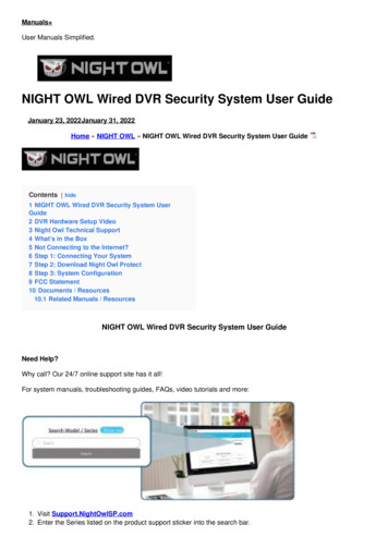
View with Rear Door OpenBack View13
EU Declaration of ConformityProduct Identification:VersaLaser SystemManufacturer:Universal Laser Systems, Inc.16008 N. 81st St.Scottsdale, AZ 85260USAEuropean Office:Universal Laser Systems GmbHLerchenfelder Guertel 43A-1160 Vienna/AustriaThe manufacturer hereby declares that the equipment specified below isin conformity with the following 95/EEC2002/96/ECC(EMC Directive)(Low Voltage Directive)(Machinery Directive)(ROHS Directive)(WEEE Directive)based on the standards listed.Standards Used:Safety:EN 60950: 2002EN 60825-1: 2007 (Class 3R)EMC:EN 55024 1998 (Class A)EN 55022: 2003 (Class A)EN 61000-3-2: 2001 (class A)EN 61000-3-3: 2002EN 61000-4-2: 2001 (4kV CD, 8kV AD)EN 61000-4-3: 2003 (3 or 10 V/m)EN 61000-4-4: 2002 (1 or 2 kV power line)EN 61000-4-5: 2001 (class 3)EN 61000-4-6: (3 or 10Vrms)EN 61000-4-8EN 61000-4-11Note: This is not a declaration of conformity. The importer of thisequipment supplies the declaration of conformity.Warning: This is a Class A product. In a domestic environment this product may cause radiointerference in which case the user may be required to take adequate measures.14
FCC ComplianceThis ULS laser system has been tested and found to comply with Federal Communication Commission (FCC)directives regarding Electromagnetic Compatibility (EMC). In accordance with these directives, ULS is required toprovide the following information to its customers.FCC Compliance Statement and WarningsThis device complied with FCC Rules Part 15. Operation is subject to the following two conditions:1. This device may not cause harmful interference, and2. This device must accept any interference received, including interference that may cause undesiredoperation.This equipment has been tested and found to comply with the limits for a Class A digital device as set forth in Part15 of the FCC Rules. These limits are designed to provide reasonable protection against harmful interferencewhen the equipment is operated in a commercial environment. This equipment generates, uses and can radiateradio frequency energy and, if not installed and used in accordance with manufacturer’s instructions, may causeharmful interference to radio communications. Operation of this equipment in a residential area is likely to causeharmful interference, in which case the user will be required to correct the interference at his or her own expense.Users should be aware that changes or modifications to this equipment not expressly approved by themanufacturer could void the user’s authority to operate the equipment.This equipment has been type tested and found to comply within the limits for a Computing Device per FCC part15, using shielded cables. Shielded cables must be used in order to insure compliance with FCC regulations.RecyclingBy placing the above symbol on our products and accessories, Universal Laser Systems is indicating that we arecommitted to helping reduce the amount of waste electronics ending up in municipal landfills. Therefore, UniversalLaser Systems urges consumers to recycle this product and its accessories. Universal Laser Systems is equippedto recycle any of its electronic products and accessories and will assist our customers with their recycling options.To arrange for recycling of your ULS product or accessory, please contact Universal Laser Systems for moreinformation at 480-609-0297 (USA), 43 1 402 22 50 (Austria), 81 (45) 224-2270 (Japan) or e-mail us atsupport@ulsinc.com.15
Chapter 3 - Installation16
This provides step-by-step instructions for site preparation, computer/software setup and laser system assemblyand connection. Follow the instructions in the order shown.1. Site Preparation2. Operating System Requirements and Software Installation3. Assembling and Connecting Your Laser SystemNote: Make sure to complete step 2 (software installation) prior to plugging the laser system into a USB porton your PC.CAUTION: Damage to the laser system due to inadequate or improper installation or operation is notcovered under the Universal Laser Systems (ULS) Warranty. See the ULS Warranty for additionalinformation. A ULS Warranty document is supplied with your laser system. Should you require a copy of theWarranty, please contact our Customer Service Team at 480-609-0297 (USA), 43 1 402 22 50 (Austria), 81 (45) 224-2270 (Japan) or e-mail us at support@ulsinc.com.Please refer to the Safety section before operating your laser system.Step 1: Site PreparationOperating Environment (User Supplied)1. The laser system must be installed in an office, laboratory, workshop or light duty manufacturingenvironment.2. Dusty or dirty environments can damage the laser system. Keep the laser system isolated from anyprocesses that produce airborne particles such as sandblasting, sanding, machining, etc. Also, keep thelaser system isolated from any equipment requiring mists of oil or water for lubrication. Airborne dust andliquids can coat and damage optics and motion system components.3. Avoid small, enclosed, non-ventilated areas. Some materials, after laser engraving or cutting, continueemitting fumes for several minutes after processing. Having these materials present in a confined,unventilated room can create a health hazard.4. For best results, since the laser cartridges are air-cooled, we recommend operating the laser systembetween the ambient temperatures of 70ºF (21ºC) and 78ºF (25ºC).5. Avoid storing the laser system outside the temperatures of 50ºF (10ºC) and 95ºF (35ºC) as excessivelycold or hot temperatures can damage the laser cartridge or reduce its lifetime.6. Ambient humidity levels must be non-condensing to protect optics.7. The laser system should be at least 1 foot (300 mm) away from any wall or obstruction to allow for accessand proper ventilation.Electrical Power Source (User Supplied)1. For your system’s electrical requirements, please refer to the “INPUT POWER” label near the power inlet.2. CAUTION: Never remove the ground lead to the electrical cord and plug the laser system into a nongrounded outlet. A laser system that is not properly grounded is hazardous and has the potential to causesevere or fatal electrical shock. Without proper grounding, the laser system may exhibit sporadic orunpredictable behavior. Always plug the system into a properly grounded (earthed) outlet.3. Noisy or unstable electricity and voltage spikes may cause interference and possible damage to theelectronics of the laser system. If electrical power fluctuations, brown outs or constant power outages area problem in your area, please contact your local Electrician to supply a power isolation and regulationmodule. Electrically noisy equipment, such as equipment with large motors, can also cause interference ifplugged into the same outlet. It may be necessary to attach the laser system to a dedicated electrical lineto resolve the problem.17
4. The laser system is designed as a Class I, Group A, pluggable device. It is also designed for connectionto IT Power systems which provide the most flexibility to the user.18
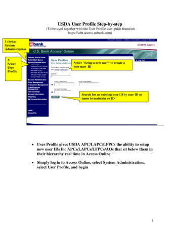
Exhaust System (User Supplied)1. We recommend you consult with a licensed contractor to meet local safety and building coderequirements.2. The exhaust system must be capable of supplying a minimum of 500 CFM (cubic feet per minute) ofairflow while under a load of 6 inches of static pressure (850m3/hr at 1.5kPa).3. Do not install forward incline, backward incline, in-line or ventilator fans because these types of airhandlers are inadequate and inappropriate for this type of installation. A high-pressure blower must beused to meet minimum airflow requirements.4. For personal safety and noise control, we recommend that the exhaust blower be mounted outside thebuilding.5. Rigid tubing should be used for the majority of the connection between the blower and the laser system.The tubing should be smooth-walled and have as few 90-degree bends as possible.6. Install an exhaust gate to adjust airflow and to close off the exhaust when the laser is not in use. Placethis gate near the laser system within 5 to 10 feet (1.50 to 3.00 meters).7. Use a short piece of industrial grade, wire-reinforced rubber tubing to connect each laser system exhaustport to an exhaust gate and secure with a hose clamp. This will provide isolate exhaust blower vibrationsfrom your laser system.8. Wire the exhaust blower electrically to a wall switch in the same room for easy ON/OFF control.Note: The following diagram shows a typical exhaust system layout. Use this as a guideline for properexhaust system installation. Although this diagram serves as an example, we recommend you consult with alicensed contractor to meet local safety, environmental and building code requirements and to also calculatethe correct size blower required for your particular installation. Length of exhaust pipe, exhaust pipe diameter,number of 90-degree angles and other restrictions must be calculated when determining the correct exhaustblower unit. Installing an undersized or oversized blower is not only unsafe, but can also lead to excessivewear and tear to the laser system and premature failure.1.2.3.4.5.6.7.8.9.Exhaust blower mounted outside (User Supplied)Weatherproof shield (User Supplied)Rigid ducting matching the diameter of the blower inlet (User Supplied)Computer (User Supplied)Y-pipe (User Supplied)Shut-off or air-flow gate (User Supplied)Flexible, wire-reinforced, industrial grade rubber hose (User Supplied)Connection to laser systemExhaust On/Off switch (User Supplied)19
Step 2: Computer Requirements and Software InstallationYour computer is a critical component in the operation of your laser system. In fact, you cannot operate the lasersystem if your computer is not connected, powered on, running Windows and running the Universal Control Panel(UCP) software.You can only run one laser system per computer. You will need to purchase a separate computer for each lasersystem you own. You must operate the laser system using the computer that is directly attached to it via theprovided 6 ft (2 meters) USB cable. USB cables longer than 6 feet (2 meters) may cause the laser system tomalfunction.Computer and Operating System RequirementsMinimum Computer Requirements (User Supplied) 2.0 GHz processor (minimum) 32 bit or 64 bit version of Windows XP, Windows Vista or Windows 7 2 GB of RAM (minimum) 40 GB hard drive (15 GB free space) (minimum) VGA monitor (minimum 1024 x 768 resolution) CD/DVD Drive Mouse and keyboard Available USB 2.0 Hi-Speed compliant port only Computer speakers (optional) Internet connection and e-mail address (optional)Note: Some computer manufacturers’ USB ports do not comply with USB 2.0 Hi-Speed standards. This maycause the laser system to exhibit erratic behavior. Confirm that your computer is USB 2.0 Hi-Speed compliantby checking your computer manual. For more information on USB 2.0 Hi-Speed compatibility, please visitwww.usb.org.Other USB peripheral devices that demand a large amount of computer processing power may slow down theoperation and productivity of the laser system. If you experience problems with operation of the laser systemwhile using another USB device, we recommend you discontinue use of that device while the laser system isin use. Do not connect or disconnect USB devices while the laser system is running a job.20
Computer Power ManagementPower management settings on your computer can interfere with proper operation of the laser system by puttingthe PC in standby or sleep mode while the laser system is processing material. The settings can be controlledthrough the power options in the Windows control panel on your PC. The illustrations below show you how todisable power management.XPVista and 7For the PowerScheme in use,select “Never” forall the options:Turn off displayandPutthecomputer to sleep.For the PowerScheme in use,select “Never” forall the options:Turn off monitor,turn off hard disks,systemstandbyand system hibernates.21
Software InstallationAt this point you need to install the Universal Control Panel (UCP) and printer driver. In order to install thesoftware, you need to have administrative privileges on the computer before starting installation. Use the SoftwareInstallation CD-ROM included with your laser system.1. Insert the Software Installation CD-ROM into your PC’s CD/DVD drive. It should automatically launch the“Universal Control Panel Installation” window. Select the laser system for which you are installingsoftware.Note: If the setup window does not automatically launch, you can launch it manually. Locate your CD orDVD drive using Windows Explorer and launch the Setup.exe application to start installation.2. The installation process will proceed as indicated by a progress bar.3. When the installation process is finished, the “Completing the ULS Software Setup Wizard” window willprompt you to reboot the PC to complete the installation. If you have any other applications running inwindows make sure you save your work prior to rebooting. After the PC finishes rebooting, the softwareinstallation is complete and you are ready to connect your laser system to the PC.22
Step 3: Assembling and Connecting Your Laser SystemFamiliarize yourself with the instructions before getting started.The final step in installation is to assemble your laser system, install the laser cartridge(s), level the laser system,make final connections and perform a beam alignment check. Do not power up your laser system until the finalstep, “Checking Beam Alignment.”CAUTION: Do not attempt to move or lift this laser system alone. Obtain assistance from additional peoplewhen lifting or carrying the laser system and make sure to secure the motion system and doors before lifting.Injury may occur if improper lifting techniques are used or the system is dropped.Machine Assembly1. Unpack the laser system.2. Remove the unassembled cart from the top of the laser system.3. Assemble the cart as it appears in the diagram below, but leave all of the screws slightly loose, except forthe casters which should be tightened as far as possible into each cart leg.a.b.c.d.e.Back panelLegs (both are identical)Side panels (two)Shelf panel1/4-20 x ½, socket head screws w/lock & flatwashers (twelve)f. Nuts (four)g. Locking casters (four are identical)h. 10-32 x 3/8 socket head screws w/lock & flatwashers (two)i. Connect to main enclosure4. With the assistance of another person, place the system on top of the cart and loosely installthe provided screws that attach the machine to the cart. These screws go up through thecart legs into the bottom of the machine.5. Open front door all the way to ensure that it does not rub on or interfere with the cart legs. Ifthe door should come in contact with the cart legs, gently pull the cart legs apart to ensurethere is noncontact between the door and the cart legs.6. Securely tighten all the screws at this point.7. Place the laser system in the desired location for operation.8. Attach your exhaust system’s wire-reinforced rubber hose to the exhaust port at the rear of the lasersystem and secure with a hose clamp.23
System Assembly VLS61. Unpack the laser system.2. Move the laser system to the location in which you intend to operate it and lock the casters.Note: If it becomes necessary to move the laser system through narrow doorways to install in itsintended location, the system can be detached from the cart and transported in two pieces. If so,follow the steps below, if not, skip to step 3.a. In the back of the system, locate the access panel shown below and remove the four screwsholding it in place.b. Locate the three white connectors and the two black connectors and disconnect all of them.24
c.Open the rear cover of the laser system.d. Locate the pocket (1) where the cables disconnected in step b reside. Gently pull the cables upand rest them on top of the sheet metal as shown below.e. Close and latch the rear cover.f. Tape the front and top doors closed using strong shipping tape, prior to lifting the laser system offthe cart, to ensure they stay closed.25
g. Locate and remove the eight screws that attach the cart to the laser system (see below).h. Lift the laser system off the cart and place the laser system front door down on a dolly fortransport.i. The cart and laser system can now be moved separately to the install location.j. Reassemble in reverse order by placing the cart into position first and locking the casters. Then,carefully line up the laser system and place it back on top of the cart.k. Bolt the laser system to the cart, re-connect the plugs and replace the access panel.26
Laser Cartridge Installation1. Make sure that your laser system power cord is not plugged in at this time. Open the rear laser coverusing the latches on top of the laser cover. Some laser systems are shipped with keyed locks so makesure the latches are unlocked.Note: Access latches for the laser cover are lockable. If you lose your keys, please contact our CustomerService Team at 480-609-0297 (USA), 43 1 402 22 50 (Austria), 81 (45) 224-2270 (Japan) or e-mail usat support@ulsinc.com for new keys.2. Locate the mounting blocks (1), the laser latches (2) and alignment forks (3). Notice that the alignmentfork has a groove (6) located between two blocks, one short (4) and one tall (5).3. Locate the “V” groove along the upper (3) and lower (2) part of the laser cartridge base plate and thealignment plate (1) at the end of the base plate.27
4. Pick up the laser cartridge by the ends and tilt it at a 30 angle as shown (1). Mount the cartridge onto themounting blocks shown in step 2 by placing the upper “V” groove on top of the mounting blocks. Slide thecartridge to the right until the outer edge (2) of the alignment plate contacts the inside edge of the tallblock of the alignment fork.5. Slowly rotate the laser cartridge down into place, making sure that the alignment plate is centered in thegroove in the alignment fork. The laser should click onto the spring loaded laser catc
7 VLS3.60 VLS4.60 VLS6.60 Laser Safety CO2 Laser, Interlocked Safety Enclosure Class 1 Red Diode Pointer Class 3R Work Area* 24 x 12 in (609.6 x 304.8 mm)