Transcription
UNVENTED WATER HEATERASSEMBLY AND OPERATION INSTRUCTIONS
GENERAL SAFETY INSTRUCTIONS1. Read the instructions and warning in this manual carefully, theycontain important information regarding safe installation, useand maintenance.This manual is an integral part of the product. Hand it on to thenext user/owner in case of change of property.2. The manufacturer shall not liable for any injury to people, animals ordamage to property caused by improper, incorrect or unreasonableuse or failure to follow the instructions reported in this publication.3. Installation and maintenance must be performed by professionallyqualified personnel as specified in the relative paragraphs.Only use original spare parts. Failure to observe the above instructions can compromise the safety of the appliance and drelieves themanufacturer of any liability for the consequences.4. DO NOT leave the packaging materials (staples, plastic bags, expanded polystyrene, etc.) within the reach of children they cancause serious injury.5. The appliance may not be used by persons under 8 years of age,with reduced physical, sensory or mental capacity, or lacking therequisite experience and familiarity, unless under supervision orfollowing instruction in the safe use of the appliance and the hazards attendant on such use. DO NOT permit children to play withthe appliance. User cleaning and maintenance may not be doneby unsupervised children.6. DO NOT ttouch the appliance when barefoot or if any part of yourbody is wet.7. Before using the device and after routine or extraordinary maintenance, we recommend filling the appliance’s tank with water anddraining it completely to remove any residual impurities.8. If the appliance is equipped with a power cord, the latter may onlybe replaced by an authorised service centre or professional technician.9. It is mandatory to screw o the water inlet pipe of the unit a safetyvalve in accordance with national regulations. In countries whichhave enacted EN 1487, the safety group must be calibrated to amaximum pressure of 1487 MPa (0,7 bar) and include at least a cock,2 / EN
check valve and control, safety valve and hydraulic load cutout.10. Do not tamper with the overpressure safety device (valve or safetygroup), if supplied together with the appliance; trip it from time totime to ensure that it is not jammed and to remove any scale deposits.11. It is normal water drips from the overpressure safety device whenthe appliance is heating. For this reason, the drain must be connected, always left open to the atmosphere, with a drainage pipeinstalled in a continuous downward slope and in a place free of ice.12. Make sure you drain the appliance and disconnect it from the power grid when it is out of service in an area subject to subzero temperatures.13. Water heated to over 50 C can cause immediate serious burns ifdelivered directly to the taps. Children, disabled persons and theaged are particularly at risk. We recommend installing a thermostatic mixer valve on the water delivery line, marked with a red collar.14. Do not leave flammable materials in contact with or in the vicinity ofthe appliance.15. Do not place anything under the water heater which may be damaged by a leak.3 / EN
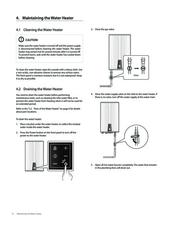
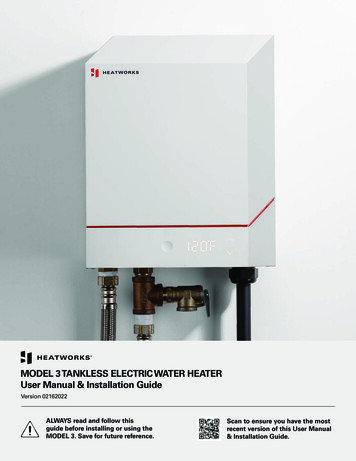
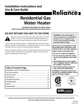
LEGIONELLA BACTERIA FUNCTIONLegionella are small rod shaped bacteria which are a natural constituent of all fresh waters. Legionaries’disease is a pneumonia infection caused by inhaling of Legionella species. Long periods of water stagnation should be avoided; it means the water heater should be used or flushed at least weekly.The European standard CEN/TR 16355 gives recommendations for good practice concerning the prevention of Legionella growth in drinking water installations but existing national regulations remain inforce.This electronic storage water heater is sold with a thermal disinfection cycle function enabled by default.Every time the product is switched on and every 30 days, the thermal disinfection cycle runs to heat thewater heater up to 60 C.Warning: when this software has been carrying out the thermal disinfection treatment, water temperature can cause burns. Feel water before bathing or showering.DESCRIPTION OF WATER HEATER21. Hot water outlet (1/2 male BSP)2. Temperature and pressure relief valve3. Cold water inlet (1/2 male BSP)4. Regulation keyboard3144 / EN
TECHNICAL CHARACTERISTICSFor the technical specifications, refer to the nameplate (the nameplate is located next to the water intake/outlet pipes).TABLE 1 - PRODUCT INFORMATIONProduct rangeWeight when emptyWeight when fullInstallationModelSMARTQelecQelec , week, smartQelec , week,Load profileLwaηwhV40Heat lossHeat up times [15-60 C]Maximum inlet pressure [rated pressure]Maximum design pressureSet operating pressure expansion valvePre-charge pressure of the expansion vesselSet opening T&P relief valveCapacitykgkgVLS /dayminutesbarbarbarbarbarL39,1%770,9646045VLS EVOVLS EVO8045 WiFi322111266VerticalVerticalRefer to the ,0%39,1%115771,3170,9641122912663,578045VLS EVO80 680The power consumption data in the table and the other information given in the Product Data Sheet(Enclosure A to this manual) are defined in relation to EU Directives 812/2013 and 814/2013.The products without the label and the data sheet for water heaters and solar devices, stipulated inregulation 812/2013, are not intended to be used in such assemblies.The device is equipped with a smart function that allows you to adapt the consumption to the user profiles. If operated correctly, the device has a daily consumption of “Qelec (Qelec, week, smart/Qelec, week) less thanthat of an equivalent product with no smart function”.This appliance is conforming with the international electrical safety standards IEC 60335-1 and IEC60335-2-21.The CE marking of the appliances attests its conformity to the following EC Directives, of which itsatisfies the essential requisites:- LVD Low Voltage Directive: EN 60335-1, EN 60335-2-21, EN 60529, EN 62233, EN 50106.- EMC Electro-Magnetic Compatibility: EN 55014-1, EN 55014-2, EN 61000-3-2, EN 61000-3-3.- RoHS2 Risk of Hazardous Substances: EN 50581.- ErP Energy related Products: EN 50440.- EN 12897:2016This product is in conformity with REACH regulations.5 / EN
Water Regulations and ByelawsThese regulations and byelaws ensure a good supply of wholesome water, and that only approvedmaterials, pipes and fittings are used to convey water.Building RegulationsThese are a statutory document and take priority over all other regulations and recommendations.The installation of an unvented hot water system of over 15 litres is classified as a “Controlled Service”and Regulation G3 applies. To meet the requirements of the regulation, installation of an unvented system should be undertaken by a “competent installer”.All installations of unvented hot water storage systems having a capacity of more than 15 litres shouldbe notified to the relevant Local Authority by means of building notice or by the submission of full plans.It is important to note that it is a criminal offence to install an unvented hot water storage system over 15litres without notifying the Local Authority.DeliveryThe products are supplied with the following:Unvented water heater (with factory-fitted T&P)Pressure relief valve set at 6 barDielectric junctionsTundishExpansion VesselCheck ValvePressure reducing Valvex1x1x2x1x1x1x1Important note: Dielectric junctions must be fitted to all models as they prevent an electrolytic reaction and safeguard against potential aggressive corrosion.If the supplied Dieletric Junctions are not fitted this could void the warranty.INSTALLING NORMS (for the installer)Before installing the heater read these instructions in full.If you are unsure please contact our technical service department (03332407777).The installation must comply with all relevant Water Regulations/Byelaws and Building Regulations.The installer should check with the local water authority for confirmation of the maximum watersupply pressure.The appliance should be left packed until it is ready to be installed. When unpacking take care not todamage the temperature and pressure relief valve on the top of the heater.A drain has to be provided for any water discharged through the safety valves.A cold water supply pressure between 1 and 3.5 bar is required (if the mains pressure is above 3.5 bara pressure reducing valve must be installed). Please note that turning down the stop-cock will reduceflow not pressure.The outlet pressure from the reducing valve (if supplied) is 3.5 bar.A 240 VAC; 3 kW single phase electrical supply is required6 / EN
This product is a device that must be installed vertically in order to operate correctly. Once installation is complete, and before any water is added or the power supply is connected, use a measuringinstrument (i.e. a spirit level) to check that the device has been installed perfectly vertical.The appliance heats water to a temperature below boiling point. It must be linked up to a mains watersupply according to the appliance performance levels and capacity.Before connecting the appliance, it is first necessary to:- Check whether the characteristics (please refer to the data plate) meet the customer’s requirements.- Make sure the installation conforms to the IP degree (of protection against the penetration of liquids)of the appliance according to the applicable norms in force.- Read the instructions provided on the packaging label and on the appliance data plate.This appliance was designed to be installed only inside buildings in compliance with the applicablenorms in force. Furthermore, installers are requested to keep to the following advice in the presence of:- Damp: do not install the appliance in closed (unventilated) and damp rooms.- Frost: do not install the appliance in areas where the temperature may drop critically and there maybe a risk that ice may form.- Sunlight: do not expose the appliance to direct sun rays, even in the presence of windows.- Dust/vapours/gas: do not install the appliance in the presence of particularly dangerous substancessuch as acidic vapours, dust or those saturated with gas.- Electrical discharges: do not install the appliance directly on electrical supplies that aren’t protectedagainst sudden voltage jumps.In the case of walls made of bricks or perforated blocks, partition walls featuring limited static, or masonry different in some way from those stated, you first need to carry out a preliminary static check of thesupporting system.The wall-mounting fastening hooks must be designed to support a weight that is three times higher thanthe weight of the water heater filled with water.Fastening hooks with a diameter of at least 12 mm are recommended.To facilitate maintenance, make sure there is a clearance of at least 50 cm inside the enclosure for access to the electrical equipment.PLUMBING WARNING:Note: If a valve i.e. a non return valve, water meter, pressure reducing valve or any type of valve orfitting that acts as a non return valve is installed on the cold water mains, this will prevent expansion.Therefore it will be necessary to install an expansion vessel (see figure below).Note: If in doubt always install a pressure reducing valve (limited to 3.5bar) and expansion vessel.The outlet from temperature and pressure relief valve/pressure relief valve must not be for any otherpurpose.Take great care not to allow any swarf into the pipe work or fittings, as this might impair the operation ofthe safety valve(s). The water connection may be carried out as per the following:7 / EN
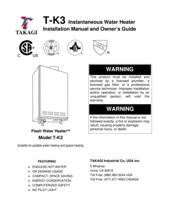
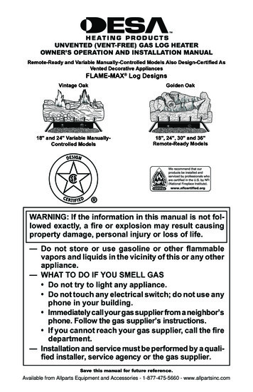
PRESSURE TEMPERATURERELIEF VALVECOLD MAINS-IN15/22 mm15 mmEXPANSIONVASSELCOMBINATIONVASSELHOT SUPPLY15/22 mmDRAIN(not supplied)EXPANSIONRELIEF PIPETUNDISHDo not fit any stop cocks or isolating valves within the distance required for expansion. If a pressure reducing valve is needed, due to a mains pressure of over 3.5 bar, an expansion control kit must be fittedregardless of expansion pipework installed. The expansion distances quoted are for 15mm pipes andcan be approximately halved for 22mm pipes.The appliance must not be supplied with water of hardness less than 12 F, not with especially hard water(greater than 25 F); we recommend installing a water softener, properly calibrated and controlled - donot allow the residual hardness to fall below 15 F.The appliance is covered under the Building Regulations and therefore it is not possible to accommodate the expansion water within the system pipe work and consequently a set of expansion controlsmust be installed.Note: The discharge from relief valves must be made in a safe and conspicuous manner.Please note that in all cases the dielectric junctions must be connected to the heater before anyother connection is made (these prevent an electrolytic reaction).8 / EN
If the supplied Dielectric Junctions are not fitted this could void the warranty.Only the use of copper pipe is recommended for connection to the heater. If any other material isused it must be able to withstand 90 C at 7 bar pressure for long periods.No valve must be fitted between the expansion/pressure relief valve and the water heater.All other required safety components to install the appliance are supplied as a kit with the appliance:15 mm pressure reducing valve set at 3.5bar. Expansion vessel (charge pressure set at 3.5bar)”DISCHARGE PIPE WORK NOTE:The following guidelines refer to Building Regulation G3. It is good practice to follow these guidelines for all relief valve discharge pipe work.1) The tundish must be vertical and fitted within 600 mm of the temperature & pressure relief valve andmust be located with the cylinder. The tundish must also be in a position visible to the occupants, andpositioned away from any electrical devices. The discharge pipe from the tundish should terminate ina safe place where there is no risk to persons in the vicinity of the discharge and to be of metal.2) Discharge pipes from the temperature & pressure relief and pressure relief valve may be joinedtogether.3) The pipe diameter must be at least one pipe size larger than the nominal outlet size of the safety device unless its total equivalent hydraulic resistance exceeds that of a straight pipe 9 m long.i.e. Discharge pipes between 9 m and 18 m equivalent resistance length should be at least 2 sizeslarger than the nominal outlet size of the safety device. Between 18 m and 27 m at least 3 times larger,and so on.Bends must be taken into account in calculating the flow resistance.See the following figure and the Table 2.4) The discharge pipe must have a vertical section of pipe at least 300 mm in length, below the tundishbefore any elbows or bends in the pipe work.5) The discharge pipe must be installed with a continuous fall.6) The discharge must be visible at both the tundish and the final point of discharge, but where this isnot possible or practically difficult; there should be clear visibility at one or other of these locations.Examples of acceptance are:i) Ideally below a fixed grating and above the water seal in a trapped gully.ii) Downward discharges at a low level; i.e. up to 100 mm above external surfaces such as car parks,hard standings, grassed areas etc. These are acceptable providing that where children may play orotherwise come into contact with discharges, a wire cage or similar guard is positioned to preventcontact, whilst maintaining visibility.iii) Discharges at high level; i.e. into a metal hopper and metal down pipe with the end of the dischargepipe clearly visible (tundish visible or not). Or onto a roof capable of withstanding high temperaturedischarges of water 3 m from any plastic guttering systems that would collect such a discharge(tundish visible).9 / EN
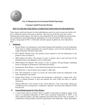
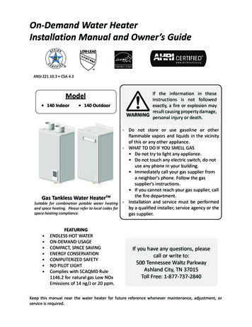
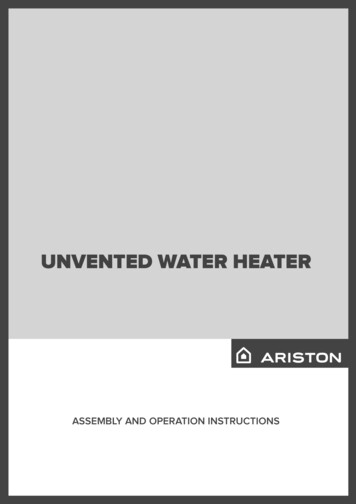
Suggest ways of terminating discharge pipes safelyTemperature & pressurerelief valveMetal discharge pipe (D1) fromtemperature & pressure relief valve.to tundish.Tundish600 mm Max.300 mmMin.Metal discharge pipe (D2) from tundishwith continuous fall. See Table 2 and workedexample.Discharge belowfixed grating.(see page 6 foralternative pointsof discharge).Fixed gratingTrapped gulleyiv) Where a single pipe serves a number of discharges, such as in blocks of flats, the number servedshould be limited to no more than 6 systems so that any installation can be traced reasonably easily.The single common discharge pipe should be at least one pipe size large than the largest individualdischarge pipe to be connected. If unvented hot water storage systems are installed where discharges from safety devices may not be apparent i.e. in dwellings occupied by the blind, infirm or disabledpeople, consideration should be given to the installation of an electronically operated device to warnwhen discharge takes place. Note: The discharge will consist of scalding water and steam.Asphalt, roofing felt and non-metallic rainwater goods may be damaged by such discharges.Table 2Sizing of copper discharge pipe “D2” for common temperature valve outletsValveoutlet sizeMinimumsize ofdischargepipe D1*G 1/215 mmG 3/422 mmG128 mm10 / ENMinimum size ofdischarge pipeD2* from tundishMaximum resistanceResistance createdallowed, expressed asby each elbow ora length of pipebend(i.e. no elbow or bends)22 mm28 mm35 mm28 mm35 mm42 mm35 mm42 mm54 mmUp to 9 mUp to 18 mUp to 27 mUp to 9 mUp to 18 mUp to 27 mUp to 9 mUp to 18 mUp to 27 m0.8 m1.0 m1.4 m1.0 m1.4 m1.7 m1.4 m1.7 m2.3 m
WORKED EXAMPLEThe example below is for a G 1/2” temperature & pressure relief valve with a discharge pipe (D2) having4 no. elbows and length of 7 m from the tundish to the point of discharge.From Table 2Maximum resistance allowed for a straight length of 22 mm copper discharge pipe (D2) from G 1/2” T& P valve is 9 m. Subtract the resistance for 4 no. 22 mm elbows at 0.8 m each 3.2 m. Therefore themaximum permitted length equates to: 5.8 m.As 5.8 m is less than the actual length of 7 m therefore calculate the next largest sizeMaximum resistance allowed for a straight length of 28 mm pipe (D2) from G 1/2” T & P valve equatesto: 18 m.Subtract the resistance for 4 no. 28 mm elbow at 1.0 m each 4 m. Therefore the maximum permittedlength equates to: 14 mAs the actual length is 7 m, a 28 mm (D2) copper pipe will be satisfactory.DRAINING THE APPLIANCEThe appliance must be drained if left inactive in a roomsubject to frost and/or in the event of prolonged inactivity.Typical drain arrangement and system designs will vary:1. Turn power off to ensure appliance is not operatedwhen empty.2. Turn off cold supply to appliance.3. Shut off hot water feed from appliance.4. Connect hose to drain cock and place other end in sink,basin etc.5. Open drain cock and open TPR valve to vent cylinder.ELECTRICAL WARNINGThe appliance must be earthedThe electrical installation must be in line with the current I.E.E. wiring regulations. A mains supply of 240VAC 3 kW (13 amps) is required (Fig. 2)Heat resisting cable, round 3 core 1.5 mm (to BS 6141 table 8) should be used to connect to the electricalsupply through either:- a 13 amp socket to BS 1363; or- a double pole fused isolating switch with a contact separation of 3 mm minimum on each pole.Flexible cables are colour coded as follows:Brown . liveBlue . neutralGreen and yellow . earth11 / EN
Fig. 2 - Wiring diagramVELIS EVOSafety relay 17d]PcW ]MZ aRZMh 7d]PcW ]MZ aRZMh 127-240 VacInputHeating elementR1R2LNSafety relay 2SensorNTC 1NTC 3NTC 2NTC 4User InterfaceA]ΧAŪ Odcc ]FR\ RaMcdaR 2QXdbc\R]cFR\ RaMcdaR HWbdMZWjMcW ]?M]dMZ DRbRcCPUEVELIS EVO WiFiSafety relay 17d]PcW ]MZ aRZMh 7d]PcW ]MZ aRZMh Heating elementR1R2127-240 VacInputLNSafety relay 2SensorNTC 1NTC 3NTC 2NTC 4IW7WMODULEUser InterfaceA]ΧAŪ Odcc ]FR\ RaMcdaR 2QXdbc\R]cFR\ RaMcdaR HWbdMZWjMcW ]?M]dMZ DRbRcE12 / ENCPU
To enter into the terminal compartment unscrew the 2 screws on the cover.(To access the screws, remove the decorative caps on the control access panel).It is mandatory, before installing the appliance, to perform an accurate control of the electrical system byverifying compliance with current safety standards, which is adequate for the maximum power absorbedby the water heater (refer to the data plate) and that the section of the cables for the electrical connection is suitable and complies with local regulations.The manufacturer is not liable for damage caused by lack of grounding or anomalous power supply.Before starting up the appliance, check that the power rating matches that given on the nameplate. Theuse of multi plugs, extensions or adaptors is strictly prohibited.It is strictly forbidden to use the piping from the plumbing, heating and gas systems for the applianceearthing connection. If the appliance is supplied with a power supply cable, should the latter need replacing, use a cable featuring the same characteristics . The power cord must be routed into the hole inthe back of the appliance and connected to the thermostat terminals (M Fig.7-8).The appliance must be grounded with a cable (yellow/green and longer than the phase cable) connected to the terminals marked(G Fig.7-8).COMMISSIONING- Check that all the necessary components are supplied and for those not factory fitted, that they arethe type recommended by the manufacturer for the particular water heater.- Check that the water heater/components are undamaged.- Check that the discharge pipe is plumbed so that it falls continuously and that no taps, valves or othershut-off devices are installed in the pipe.- Check that the discharge pipe drains safely to waste and is readily visible.- Check, in the case where some components are not factory fitted, that they are marked so as to referto the warning label on the water heater.- Open all outlet taps.- Turn on the mains water supply.- Close taps in turn as water flow stabilises with no air bubbles.- Check for leaks.- Check that no water is passing through the safety valve(s).- Test the operation of the safety valve(s) by lifting/turning the lever/knob, and observing that waterflows through and safely to waste.- Switch on electricity and set thermostat to at 60 C to reduce the build up of scale in hard water areas.- Check the water heats up.- Check that warning to user label is secure and visible on the heater and related warning labelsare fitted to the controls.- Demonstrate operation to user, including operation of safety valve(s) and what to do if it/they operate(s).- Give this handbook to the user and discuss future maintenance.- Drain and refill the entire system ensuring it is flushed in accordance with BS6700.13 / EN
MAINTENANCE REGULATIONS (for qualified personnel)Before calling your Technical Servicing Centre, check that the fault is not due to lack of water or power failure.Caution: disconnect the appliance from the mains before conducting any maintenance work.Replacing partsThe electrical parts may be accessed by removing the cover (Fig. 7, 8).Intervene on the power board (Ref. Z) by disconnecting the cables (Ref. C, Y and P) and remove the screws.Intervene on the control panel by first removing the power board (Ref. Z). The display board is attached to theproduct through two fixing side flaps (A Fig. 4a) accessible from inside the lower cover.Release the control panel fixing flaps using a flat screwdriver to pry upon the same (A Fig. 4b) and releasethem from the pins, simultaneously push it outwards to free it from the seat. Repeat for both fixing flaps. Payspecial attention not to damage the plastic flaps as breaking them will not allow for correct assembly of thepanel in its seat, resulting in possible aesthetic defects. After removing the control panel, you can disconnectthe connectors of the rod carrying sensors and power board. Intervene on the rod carrying sensors (Ref. K) bydisconnecting the wires (Ref. F) from the control panel and remove it from its seat, taking care not to excessively bend them.During reassembly, make sure that all components are put back in their original positions.To work on the heating elements and anodes, first drain the appliance (refer to the related paragraph).Remove the bolts (C Fig. 5) and remove the flanges (F Fig. 5). The flanges are coupled to the heating elementsand anodes. During reassembly, make sure to restore the rod carrying sensors and the heating elements tothe original positions (Fig. 5, 7, 8). Make sure that the flange plate with the coloured writing H.E.1 or H.E.2, ismounted in its position marked by the same writing.We recommend replacing the flange gasket (Z Fig. 6) every time it is disassembled.Only for models equipped with user interface shown in figure 8. Se si deve sostituire l’anodo a corrente impressa (Rif. Q), unscrew the nut, disconnect the cable and unscrew the anode from the flange.When you are putting it back in, replace the gasket, tighten the anode to a maximum torque of 2.5 Nm, connectthe cable and tighten the relative nut to a maximum torque of 0.6 Nm.CAUTION! The reversal of the heating elements involves malfunction of the appliance.Work on one heating element at a time and remove the second only after replacing the first.Use only original spare parts.Periodical maintenanceThe heating element (R fig. 6) should be descaled every two years to ensure it works properly (R Fig. 6) approximately every two years (the frequency must be increased, if water is very hard).If you prefer not to use special liquids for this operation, simply crumble away the lime deposit without damaging the heating element.The magnesium anodes (N Fig. 6) must be replaced every two years (this does not apply to appliances withstainless steel boilers); however, the anode should be checked every year if the water is corrosive or chloriderich. To replace them, remove the heating elements and unscrew them from the brackets.The bypass pipe (X Fig. 7, 8) is inspected in the event of fault due to its obstruction. To inspect it remove thetwo rings (W Fig. 7, 8).After routine or extraordinary maintenance, we recommend filling its tank with water and draining it completely so as to remove any residual impurities. Use only original spare parts supplied by the manufacturer’s authorised service centres.14 / EN
USER INSTRUCTIONSAdvice for user- Avoid positioning any objects and/or appliances that could be damaged by water leaks beneath the waterheater.- Should you not use any water for an extended period of time, you should: disconnect the appliance from the electrical supply by switching the external switch to ‘’OFF”; turn off the plumbing circuit taps;- Hot water at above 50 C flowing out of the taps at the point of use could cause serious scalds or even deathfrom burns. Children, the disabled and the elderly are more exposed to the risk of burns. It is strictly forbidden for the user to perform any routine or extraordinary maintenance.To clean the external parts use a damp cloth soaked in soap and water.Adjusting the temperature and activating the functions (Fig. 9-10)The product is set to “Manual” by default, with a temperature set to 65 C and the function “ECO EVO” is active.In case of a power failure or if the product is switched off using the button ON/OFF (Ref. A), the last temperatureset remains saved.Slight noise may occur during the heating phase due to the water being heated.Switch the appliance on by pressing the ON/OFF button (Ref. A). Set the desired temperature by selecting alevel between 40 C and 65 C using the “ “ and “ - ·:buttons. During the heating phase, the LEDs (Ref. 1-5)related to the temperature reached by the water remain on; the subsequent ones, until the temperature isset, flash progressively. If the temperature drops, for example due to water being drawn, the heating is automatically reactivated and the LEDs between the last one on (steady) and that related to the set temperaturestart to flash progressively again.ECO EVO FUNCTIONThe “ECO EVO” function is a software program that automatically “learns” user consumption levels, reducing heat loss to a minimum and maximising energy savings. The “ECO EVO” software consists of aninitial saving period of a week, when the product begins to operate at the temperature set. Al the endof this “le arning” week, the software adjusts water heating according to the user’s real needs which areautomatically identified by the appliance. The product guarantees a minimum reserve of hot water evenduring periods in which water is not withdrawn.The hot water demand learning process, continues even after the first week. The process achievesmaximum efficiency after four weeks of learning.Activate the function by pressing the corresponding button, which will light up. In this mode, the manualselection of the temperature is possible, however changing iidisables the “ECO EVO” function.Reactivate it by pressing the “ECO” button.Whenever the “ECO EVO” function or the product is turned off and on again, the function will continueto le arn the levels of consumption. In order to guarantee proper operation of the program, it is recommended not to disconnect the appliance from the mains. An internal memory ensures data storage forup to four hours wi thout electricity, after which all acquired data is cancelled and the learning processwill begin from the start. Each time the knob is rotated to set the temperature, the “ECO EVO” functionis automatically disabled and the relative writing turns off. The product continues to operate with theprogram selected, the ECO function is not active.To voluntarily cancel the acquired data, hold down the “ECO” button for more than 5 seconds. When thereset process is completed, “ECO” flashes quickly to confirm data cancellation15 / EN
SHOWER READY FUNCTIONFor model equipped with user interface type shown in figure 9The product is equipped w
Product range VLS EVO 45 VLS EVO 80 VLS EVO 45 WiFi VLS EVO 80 WiFi Weight when empty kg 21 32 21 32 Weight when full kg 66 112 66 112 . - ErP Energy related Products: EN 50440. - EN 12897:2016 This product is in conformity with REACH regulations. 6 / EN Water Regulations and Byelaws