Transcription
7 Series HD SDI IPDual Output PTZ CameraUSER MANUALVERSION: VCC-7HD-M-02202021VCC-7HD20S-3SMNVCC-7HD30S-3SMN 2021 Bolin Technology1
ContentsIMPORTANT INFORMATION . 4WHAT’S IN THE BOX . 7OVERVIEW . 8FEATURES . 8CAMERA DIAGRAMS . 9REMOTE CONTROLLER . 11SYSTEM CONFIGURATION . 12OBTAIN VIDEO SIGNAL . 13AUDIO IN / OUT . 14SD CARD (NOT ACTIVATE, FOR FUTURE SUPPORTED BY SOFTWARE UPGRADE) . 14CAMERA CONTROL METHODS AND SYSTEM CONFIGURATIONS . 15USE THE INFRARED REMOTE CONTROLLER . 15USE RS-232 (VISCA) . 15USE RS-422(VISCA) / RS485 (PELCO P/D) . 17RS422 (VISCA) CONNECTION . 17PELCO P/D KEYBOARD RS485 CONNECTION . 19HOW TO MAKE THE CONNECTION WITH BOLIN PRODUCTS . 20VISCA OVER IP CONTROL . 21VISCA OVER IP NETWORK CONFIGURATION . 21TALLY LIGHT GPI I/O CONNECTION. 22DIP SWITCH SETTINGS . 25ADJUSTING AND SETTING WITH MENUS . 27EXPOSURE MENU . 28WHITE BALANCE MENU. 29PICTURE1 MENU. 30PICTURE2 . 31NETWORK . 31PAN TILT ZOOM MENU . 32SYSTEM MENU. 33FIRMWARE UPGRADE . 34UPGRADING MCU FIRMWARE . 34UPGRADING IP ENCODER FIRMWARE . 34OPERATION USING THE INFRARED REMOTE CONTROLLER. 35PAN/TILT AND ZOOM OPERATION . 35OPERATING MULTIPLE CAMERAS WITH INFRARED REMOTE CONTROLLER. 36ADJUSTING THE CAMERA FOCUS . 362
STORING THE CAMERA SETTINGS IN MEMORY — THE PRESETTING FEATURE . 37MENU CONFIGURATION . 41DIMENSION . 433
Operating InstructionsThank you for purchasing our product. If there are any questions, please contact the authorized dealer.Before operating the unit, please read this manual thoroughly and retain it for future reference.CopyrightCopyright 2015-2018 Bolin Technology all rights reserved. No part of this manual may be copied, reproduced,translated, or distributed in any form or by any means without prior consent in writing from our company.Trademark Acknowledgementand other Bolin's trademarks and logos are the property of Bolin Technology Other trademarks,company names and product names contained in this manual are the property of their respective owners.Trademarks and Registered Trademark Acknowledgement Microsoft, Windows, ActiveX, and Internet Explorer are registered trademarks of Microsoft Corporation in theU.S. and/or other countries.HDMI, the HDMI logo and High-Definition Multimedia Interface are the trademarks or registered trademarks ofHDMI Licensing, LLC in the United States and other countries.The Software may contain h.264/AVC video technology, the use of which requires the following notice fromMPEG-LA, L.L.C.:THIS SOFTWARE IS LICENSED UNDER THE AVC PATENT PORTFOLIO LICENSE FOR THE PERSONAL ANDNON-COMMERCIAL USE OF A CONSUMER TO (I) ENCODE VIDEO IN COMPLIANCE WITH THE AVCSTANDARD ("AVC VIDEO") AND/OR (II) DECODE AVC VIDEO THAT WAS ENCODED BY A CONSUMERENGAGED IN A PERSONAL AND NON-COMMERCIAL ACTIVITY AND/OR WAS OBTAINED FROM A VIDEOPROVIDER LICENSED TO PROVIDE AVC VIDEO. NO LICENSE IS GRANTED OR SHALL BE IMPLIED FORANY OTHER USE. ADDITIONAL INFORMATION MAY BE OBTAINED FROM MPEG LA, L.L.C. SEEhttp://www.mpegla.com. HEVC/h.265 Covered by one or more claims of patents listed at patentlist.hevcadvance.comHDBaseT is a trademark of the HDBaseT Alliance.ONVIF trademarks and logos are to be used per the guidelines established in this and other ONVIF policies anddocuments including the ONVIF Rules of Membership and the ONVIF Logo Guidelines1.Other trademarks, company names and product names contained in this manual are the property of their respectiveowners.IMPORTANT INFORMATIONLegal NoticeAttention:To ensure account security, please change the password after your first login. You are recommended to set a strongpassword (no less than eight characters). Password login does not apply to some models that do not need password login.The contents of this document are subject to change without prior notice. Updates will be added to the new version of thismanual. We will readily improve or update the products or procedures described in the manual.4
Best effort has been made to verify the integrity and correctness of the contents in this document, but no statement, information,or recommendation in this manual shall constitute formal guarantee of any kind, expressed or implied. We shall not be heldresponsible for any technical or typographical errors in this manual.The product appearance shown in this manual is for reference only and may be different from the actual appearance of yourdevice.This manual is a guide for multiple product models and so it is not intended for any specific product.In this manual, the illustrations of displayed interface, parameters displayed, drawings and value ranges may vary with models.Please see the actual product for details.Due to uncertainties such as physical environment, discrepancy may exist between the actual values and reference valuesprovided in this manual.Use of this document and the subsequent results shall be entirely on the user’s own escriptionContains important safety instructions and indicates situations that may cause bodily injury.User must be careful and improper operations may cause damage or malfunction of product.Indicates useful or supplemental information about the use of product.Safety InformationWARNING!Installation and removal of the unit and its accessories must be carried out by qualified personnel. You must read all ofthe Safety Instructions supplied with your equipment before installation and operation.Warnings: If the product does not work properly, please contact your dealer. Never attempt to disassemble the camera yourself.(We will not assume any responsibility for problems caused by unauthorized repair or maintenance.) This installation should be made by a qualified service person and should conform to all the local codes. When shipping, the camera should be packed in its original packaging. Make sure the power supply voltage is correct before using the camera. Do not drop the camera or subject it to physical shock. Do not touch sensor modules with fingers. If cleaning is necessary, use a clean cloth with a bit of ethanol and wipe itgently. If the camera will not be used for an extended period of time, put on the lens cap to protect the sensor from dirt. Do not aim the camera lens at the strong light such as sun or incandescent lamp. The strong light can cause fataldamage to the camera.Maintenance Precautions: If there is dust on the front glass surface, remove the dust gently using an oil-free brush or a rubber dust blowingball. If there is grease or a dust stain on the front glass surface, clean the glass surface gently from the center outward5
using anti-static gloves or an oil-free cloth. If the grease or the stain still cannot be removed, use anti-staticgloves or an oil-free cloth dipped with detergent and clean the glass surface gently until it is removed. Do not use organic solvents, such as benzene or ethanol when cleaning the front glass surface.Regulatory ComplianceFCC Part 15This equipment has been tested and found to comply with the limits for digital device, pursuant to part 15 of the FCCRules. These limits are designed to provide reasonable protection against harmful interference when the equipment isoperated in a commercial environment. This equipment generates, uses, and can radiate radio frequency energy and, ifnot installed and used in accordance with the instruction manual, may cause harmful interference to radiocommunications. Operation of this equipment in a residential area is likely to cause harmful interference in which casethe user will be required to correct the interference at his own expense.This product complies with Part 15 of the FCC Rules. Operation is subject to the following two conditions:This device may not cause harmful interference.This device must accept any interference received, including interference that may cause undesired operation.LVD/EMC DirectiveThis product complies with the European Low Voltage Directive 2006/95/EC and EMC Directive2004/108/EC.WEEE Directive–2002/96/ECThe product this manual refers to is covered by the Waste Electrical & Electronic Equipment (WEEE)Directive and must be disposed of in a responsible manner.6
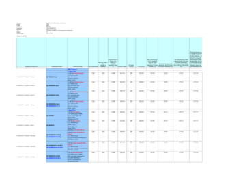
WHAT’S IN THE BOXNote: The camera color may be in white or black per the item that is purchased.Accessories (Optional)7
OverviewThis user guide is suitable for the following models:VCC-7HD30S-3SMNFeatures Resolution: Up to 1080P60, 1080i59.94IP Resolution: Up to 1080P60, 1080P30Zoom: Optical 30XImage stabilizer(20X) and true WDR 130dBVideo Output: HDMI, 3G-SDI, IP, CVBS simultaneously 350-degree continuous pan, 120-degree continuous tilt128 presets, Speed up to 150 degrees/secStandard mounting and ceiling mounting with E-Flip functionControl supports RS-232 control, RS-422/485 control, VISCA-over-IP, IP-Onvif*, CGI*, IP controlsoftware*, IR Remote ControllerPresets store camera directions and image parameters. (Up to 6 presets on remote controller or128 presets via protocol programming.)Image parameter setting restore with presets and quick access operationIP Protocol RTSP, RTMP for online video streaming.Local storage Micro SD card up to 32GB supported.Supports Audio input, Audio output with IP streaming.Power: DC 12V, PoE (IEEE802.3at)Firmware upgrade via USB2.0 or IP*Features to be supported on future firmware release.8
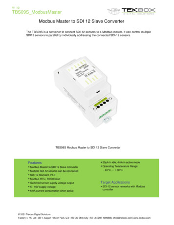
Camera Diagrams9
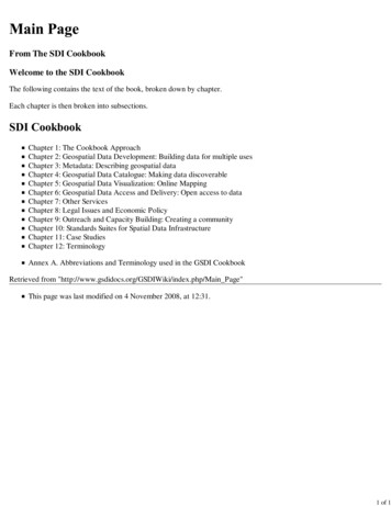
1. Front Tally Light2. IR Remote Controller SensorsThese are sensors to receive commands from infrared remote controller.3. LensThis is a 30X magnification optical zoom lens4. Power LED IndicatorTurns green when the camera is connected to power outlet. When the power is turned on, it takes about 15 to 30seconds to display the image after LED turns on.5. Back Panel6. 12V DC Power PortConnect the supplied DC power adaptor and cord.7. RS232 Control Port (RJ45)RJ45 to RS232 convertor cable is provided.8. RS-422 Control Port (RJ45)RJ45 to RS422 convertor cable is provided9. RJ45 Port for IP Network Video Streaming or PoE power supplyFor VISCA over IP control and IP video streaming with POE (IEEE802.3bt) power input when it is used as IPNetwork Port;10. HDMI Port (HDMI 1.4)11. 3G-SDI Video Output12. USB2.0 PortFor firmware upgrade only13. Video Format SelectorFor video format selection14. IR Remote ID SelectorCamera ID for IR remote controller15. Micro SD Card Port16. Audio Output/Input (Line-in/out)17. CVBS Video Output18. Bottom piece screws (Open them without authorization will violate warranty regulation)19. Fix Mounting HolesFor original wall/ceiling mount bracket20. Tripod mounting holes21. Bottom DIP Switch10
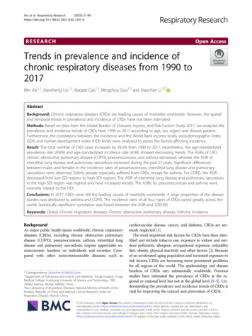
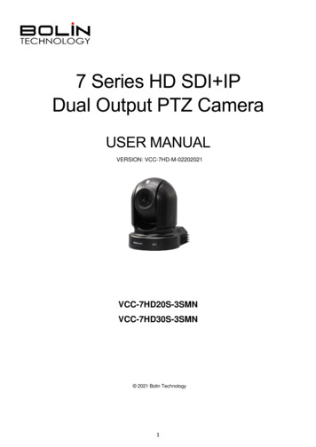
Remote 7.18.MENU, on screen menu display ON/OFFCamera IR ID Selector for Remote Control.AI Features, available when AI button (13#) is pressed. (Not activated, for future use).Positioning Function and Number Buttons Preset Position Calling and SettingValue adjusting for Feature Item NO.11.Preset button, to set preset position.Zoom. Telescope and Wide with slow speed.Auto Framing. (Not activated).Direction Control PAN-TILT direction control OSD menu navigator HOME: Home position, confirm button, Enterbutton.FOCUS Manual Focus, Far, Near Auto FocusFeatures Direct Control, work with Value Adjust key and – to make the feature adjustments. Gain, Image gain adjustments Color, Image color saturation adjustments Black L, Image Black Level adjustments WB.R, Image White Balance Red adjustments PT S, Pan/Tilt Speed adjustments Zoom S, Zoom Speed adjustments Preset S, Preset Speed adjustments WB.B, Image White Balance Blue adjustments WDR, Wide Dynamic Range adjustments Freeze, To get a frozen image. B Light, Back Light compensation OPW, One Push White BalanceVideo Format Switching, Works with pressing andholding Fn button. You can change the video format by keeppressing the button. (When video format ischanged, the camera would restart and thescreen turns black for few seconds.)AI Mode key (Not activated, for future use) Press AI button once, then press one of the AIfeatures (Printed in color blue).Power (Press and hold for 3 second) Power ON the camera to turn the camera inoperation status. Power OFF the camera to turn the camera instandby status. When the camera is powered OFF, thecamera turns to the back and would be onstandby mode. When the camera is powered ON, the camera turns to the front. Powering the camera ON/OFF would not restart the camera.Fn Function Mode key Press and hold the Fn key, and press one of the function buttons that printed in color brown.Reset button, to cancel preset that has been set.Zoom. Telescope and Wide with fast speed.One Push AF Press once to focus.Notes AAA Battery is not included with the remote controller.11
System ConfigurationConnectionWhen the camera is connected to a computer and joystick keyboard with a VISCA cable (cross type, RS-232), you canoperate the camera with the computer and the joystick keyboard.When the camera is connected to a joystick keyboard a control cable (cross type, RS-422/485), you can operate thecamera’s pan, tilt, zoom with the joystick keyboard.In this connection configuration, HDMI cable, SDI video cable, data cable, Network cable is required. To obtain these thirdparty components or accessories, consult the dealer where you bought your camera.Power Use only the DC power adaptor (JEITA type4) supplied with the unit. Do not use anyother DC power adaptor.If using POE to power the camera, PoE (IEEE802.3at) is supportedEnsure that the POE power source has sufficient power budget to power the camera, or some features may notfunction properly.Cable Requirements Network Cable: 10/100 Mbps Ethernet CAT5/5E/6 UTP cables are applicable to theANSI/EIA/TIA-568A/B and ISO/D. Eightwires in the network cable need to beinserted in parallel into the top of the cableconnector. The cable connector needs to becrimped in position. When the cableconnector is in position, ensure that the metalpieces of the cable connector are parallel toeach other and the clamp of the cableconnector is intact.SDI Cable: For broadcast use,Belden1694A/5CFB is a suitable cable totransmit broadcast-quality video:12
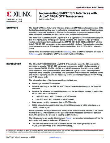
Conductor:AWGStrandingMaterialNominal Diameter18SolidBare Copper0.04 in.Shield MaterialTypeLayerMaterialCoverageTape1Aluminum / Polyester / Aluminum100%Braid2Tinned Copper95%Nom. CapacitanceConductor to shieldNom. InductanceNom. Char. Impedance16.2 pF/ft0.106 µH/ft75 OhmObtain Video SignalThe camera can simultaneously have SDI video output and HDMI video output and IP video output.HDMI HD Video signal1. Connect the camera to a HD monitor/TV using HDMI cable.2. Turn on the camera, video will display on the monitor after running initializing.3. Information of the camera initial setting status will display for 5 seconds.4. You can set the video format of the camera to the one you want to display.SDI Video SignalThe camera can simultaneously stream SDI video output with HDMI video output.1. Connect SDI cable in between the camera your SDI Device/display.2. You now have SDI video output.3. SDI video only supports 1080P.IP Video SignalThe camera can simultaneously stream IP video output and SDI video output and HDMI video output.1. Connect the camera to the network using Cat5/Cat6 network cable.2. You need to have a web browser or VMS client software ready for IP video streaming.3. PELCO address and Baud Rate setting on the camera must be as same as the setting on camera IP WEBinterface.4. To obtain IP video and configure IP video, please refer to Network Camera User Manual Part Two.CVBS Video Signal1. Connect CVBS cable in between the camera and your CVBS Device/display.2. You now have CVBS video output.Camera Initial setting status InformationInformation of the camera initial setting status will display for 5 seconds.1. Camera PELCO ID for RS-485 control2. Camera ID for IR Remote Controller3. IR remote control signal receive current setting4. Baud Rate current setting5. Control COMM Port current setting6. Video format current setting7. HDMI current setting8. Model number9. Firmware version13Camera Status Info DisplayPELCO ID001IR ID01IR-RECEIVEONBAUD RATE9600COMM TYPE232FORMAT1080P29.97HDMI OUTRGBMODEL TYPE---SV:V0B220B10040AA005
Audio IN / OUT On real panel, a microphone or audio source can beconnected to the Audio IN port, which feeds audio into thecameraA speaker can be connected to the Audio OUT port, whichwill output any audio that is captured on the Audio In portSee Manual part 2 for more information about Audio capture Table: Audio input & output relationshipAudio InputMic Built-inAudio LineInSDI AudioEmbeddedNOHDMI AudioEmbeddedNOIP AudioOutputNO*AudioLine- outYES, IP AudioYESYESYESYES, IP AudioSD Card (Not Activate, for future supported by software upgrade)Micro SD card can be inserted to the camera for local recording. Ensure that the Micro SD card’s pins are faced downward (logo faced up)Slide the card into the slot, and click into placeTo remove the card, click inward, and it will pop outward and may be removedSee Manual part 2 for more information regarding SD recordingCurrently, the following Micro SD cards are TransferBusIU1IU1IU1IU1IU1UHS-I (1)UHS-I (1)UHS-I (1)UHS-I (1)UHS-I (3)U1U114
Camera Control Methods and System ConfigurationsThis unit has multiple ways of controlling the camera and various system configuration capabilities using optionalproducts. This section describes the ways of controlling and typical system examples with the required components andusage of each system.1. Use the Infrared Remote Controller2. Use RS-232 (VISCA)3. Use RS-422/485 (VISCA/PELCO P/D)4. IP Control (See Network Camera User Manual)Use the Infrared Remote ControllerTo operate the camera from a short distance.For IR remote control details, refer to Operation Using the Infrared Remote Controller.Use RS-232 (VISCA)You can use RS-232 port to connect to optional controllers, such as joystick control keyboard, control PC station, tooperate the camera.To perform pan/tilt and zoom operations using the joystick of the control keyboard, and to perform the Preset operationusing the control buttons.An application software that supports this unit is needed if you use PC station.RS232 Connection1.2.3.4.5.6.7.Set RS232 control method on Bottom Dip Switch.Set Baud Rate on Bottom Dip Switch to the same as Baud Rate setting on the keyboard you are using.Set specific camera address that you want to control the camera for on Bottom Dip Switch.If you want to have the camera address to be automatically assigned by VISCA controller, set camera Dip Switch address to0.Reboot the camera by turning it Off/On after the Bottom Dip Switch has been set up correctly.Camera supports Daisy Chain connection up to 7 cameras.Use the RJ45 to RS232 (VISCA) control cable. The controller must be VISCA compatible.15
8.You can make RS232 connection cable if you have the following applications:9.Use extension cables included RJ45 to RS232 8 pin Mini Din adaptor to make RS232 connection for your control device.10. Use extension cables included RJ45 to RS422/232 Phoenix terminal contact adaptor to make RS232 connection for yourcontrol device.11. Or you can use CAT5/6 network cable (T-568B standard pinout) to make RS232 connection by following thepin definition below:16
12. How to make RS232 Daisy Chain multiple camera connection with standard RS232 serial port controller asbelow:Use RS-422(VISCA) / RS485 (PELCO P/D)You can use RS-422/485 port connect to optional controllers, such as joystick control keyboard, control PC station, tooperate the camera.To perform pan/tilt and zoom operations using the joystick of the control keyboard, and to perform the Preset operationusing the control buttons.An application software that supports this unit is needed if you use PC station.RS422 (VISCA) connection1.2.3.4.5.6.7.8.Set RS422 control method on Bottom Dip Switch.Set Baud Rate on Bottom Dip Switch to the same as Baud Rate setting on the keyboard you are using.Set specific camera address that you want to control the camera for on Bottom Dip Switch.If you want to have the camera address to be automatically assigned by VISCA controller, set camera Dip Switch address to0.Reboot the camera by turning it Off/On after the Bottom Dip Switch has been set up correctly.Use the RJ45 to RS422 control cable. The controller must be VISCA compatible.Camera supports Daisy Chain connection up to 7 cameras.The connection of SONY keyboard is different than other VISCA (Non-Sony) keyboard.17
9.How to make RS422 connection and RS422 Daisy Chain multiple cameras connection with SONY controller as belowSONY Keyboard RS422 Connection10. How to make RS422 connection and RS422 Daisy Chain multiple cameras connection with Non-Sony controller as below:VISCA (Non-Sony) Keyboard RS422 Connection11. Use extension cables RJ45 to RS422 Phoenix connecter adaptor included to make RS422 connection for your control device.12. Or you can use CAT5/6 T-568B Standard Ethernet cable direct connect between the camera and the controller to makeRS422 connection by following the pin definition below:18
13. How to make RS422 Daisy Chain multiple camera connection with RS422 standard serial port controller:PELCO P/D Keyboard RS485 ConnectionNOTE: Use RS422 ports for RS485 connection. Only use TX and TX- for RS485 connection. Set RS422 control method on Bottom Dip Switch.Set Baud Rate on Bottom Dip Switch to the same as Baud Rate setting on the keyboard you are using.Set the camera ID on OSD menu by remote controllerReboot the camera by turning it Off/On after the Bottom Dip Switch has been set up correctly.Use PELCO P/D compatible keyboard.Use preset 95# on the keyboard to bring up/exit camera OSD menu.Use joystick and Button “OPEN” or “CLOSE” to navigate OSD menu.To operate keyboard, please refer to the user manual of the keyboard you are using.PELCO RS485 Connection Use extension cables included RJ45 to RS422 Phoenix connecter adaptor to make RS485 connection for your control device.19
Or you can use CAT5/6 T-568B Standard Ethernet cable direct connect between the camera and the controller to makeRS485 connection by following the pin definition below: How to make RS485 multiple cameras connection with RS485 standard serial port controller:NoteFor RS-232 VISCA control, this unit supports daisy chain connection for using multiple cameras.For control details, refer to Operating Instructions of control keyboard/station software. You need to match the communication speed (Baud Rate) between the camera and the joystick controller. You cannot use the RS-232 connections while you are using the RS422/485 connection.Operating Multiple Cameras Using RS-232,422/485 Using RS-232 (VISCA), you can connect to 7 cameras. Using RS-422 (VISCA), you can connect to 7 cameras. Using RS-485 (PELCO), you can connect to 255 cameras. Using RS-485 (PELCO), all camera addresses must be set up before the connection. You can set the cameraaddress by operating OSD menu, or by setting the Dip Switch on the bottom of the camera. In this case, you canuse multiple control keyboards.How to make the connection with BOLIN productsPlease see the User Guide “BOLIN Camera and Keyboard Controller Connection”that you can download it at www.bolintechnology.com product pages.20
VISCA over IP ControlWith VISCA over IP function, you can control the camera using VISCA protocol on a controller equipped withIP communication capabilities via LAN.The communication specifications of VISCA over IP are followings: Interface: RJ-45 10/100MInterface protocol: IPv4Transport protocol: UDPIP address: 192.168.0.13 By defaultPort: 52381VISCA over IP Network ConfigurationRe-assign the cameraThe default information of the IP camera is following: Static IP: 192.168.0.13 Subnet mask: 255.255.255.0 Gateway: 192.168.0.1 VISCA over IP control port: 52381.The camera IP address needs to be assigned to the IPaddress that works wi
11. 3G-SDI Video Output 12. USB2.0 Port For firmware upgrade only 13. Video Format Selector For video format selection 14. IR Remote ID Selector Camera ID for IR remote controller 15. Micro SD Card Port 16. Audio Output/Input (Line-in/out) 17. CVBS Video Output 18. Bottom piece screws (Open them without authorization will violate warranty .