Transcription
Aircraft Flight ManualRDASS HDPart # 27670003Revision 07-17-2017
Table of Contents1.Introduction . 11.1 Documentation Conventions . 11.2 Abbreviations and Terms . 21.3 Notes, Cautions, and Warnings . 42.RDASS System Description . 72.1 List of Components . 72.2 DX9 Radio Controller Switchology . 122.3 HD Video Monitor . 163.PC Ground Control Station . 173.1 Ground Control Station Components . 173.2 Ground Control Station Procedures . 174.3.2.1Link Ground Control Station to the Aircraft . 173.2.2Create a Flight Plan Using Photogrammetry Tool . 183.2.3Create a Flight Plan Using a Template . 183.2.4Edit, Save, and Recall a Flight Plan . 20Battery Procedures . 214.1 Battery Safety. 214.2 Charging the Radio Controller. 234.3 Charging the GoPro . 244.4 Testing LiPo Battery Voltage . 244.5 Charging Sony α6000 Battery . 244.6 Charging LiPo Flight Batteries . 254.7 Charging the Video Monitor . 264.8 Lipo Battery Storage Procedures . 275.iiCameras . 28
5.1 GoPro Hero4 . 285.1.1Common GoPro Operations . 295.1.2Take Time Lapse Photos . 295.1.3GoPro Camera Specifications . 295.1.4GoPro Hero4 Menus . 305.1.5GoPro Status Screen. 315.2 FLIR Vue and FLIR Vue Pro . 325.2.1FLIR Vue and FLIR Vue Pro Specifications . 325.3 Sony α6000 . 335.3.1Sony α6000 Camera Specifications . 345.4 MicaSense RedEdge . 355.4.1MicaSense RedEdge Camera Specifications . 355.5 Additional Ethernet Out . 366.GeoReferencer . 376.1 GeoReferencer Components . 376.2 Configuring the GeoReferencer . 377.Flight Procedures . 397.1 Course Lock Procedure . 397.2 Point of Interest Procedure. 407.3 Go-Home Procedure . 417.4 Remote Control Take Back Procedure . 427.5 Camera Selection . 437.6 Gyro-Stabilized Gimbal Initialization . 437.7 Operating the Navigation Lights . 438.HD Flight Checklist . 448.1Crew Brief. 46iii
8.29.9.19.210.ivLED Autopilot Status Lights . 47Performance and Limits . 49Aircraft Specifications . 49Flight Time Calculation . 49User-Level Maintenance . 5010.1Rotor Removal . 5010.2Rotor Installation . 5110.3Compass Calibration . 5210.4IMU Calibration . 53
1. INTRODUCTIONCongratulations on your purchase of the Leptron RDASS. TheLeptron RDASS offers a superior aerial data collection platform.Leptron provides this manual to support safe, effective, and legaloperations of our small Unmanned Aircraft System (sUAS). Youcan ensure that you are getting the maximum benefit from yoursUAS by strictly observing all operating procedures and practicesoutlined in this manual. You should regularly check leptron.comfor updates to this manual, as this manual is subject to changewithout notice.1.1 Documentation ConventionsAn operating procedure, condition, etc., whichis essential to highlight.NOTEAn operating procedure, practice, etc. which, ifnot strictly observed, could result in damage toor destruction of equipment.CAUTIONWARNINGSHALL:WILL:SHOULD:MAY:An operating procedure, practice, etc., which,if not correctly followed, could result inpersonal injury or loss of life.Used to indicate a mandatory requirementUsed to express a declaration of purposeUsed to indicate a nonmandatory but preferredmethod of accomplishmentUsed to indicate an acceptable method1
1.2 Abbreviations and Terms(AGL) AboveGround Level(ATC) Air TrafficControl(COA) Certificate ofWaiver orAuthorization(FOV) Field ofView:(FPV) First PersonView(FTF) FunctionalTest Flight:(IOC) IntelligentOrientationControl:(LiPo) LithiumPolymer:(MTR) MilitaryTraining Route:Night2Altitude measured with respect to theground surface. This is as opposed toaltitude measured above mean sealevel (MSL).The ground-based personnel andequipment concerned with monitoringand controlling air traffic within aparticular area.An authorization issued by the AirTraffic Organization to an operator for aspecific unmanned aircraft activity.The area in front of a camera or sensorthat can be observed instantaneously.A method used to control a radiocontrolled aircraft looking from the pointof view of an on-board camera.A series of flight maneuvers used toverify functionality controllability of theaircraft and associated flight equipmentthroughout various flight regimes.IOC modes consist of Course Lock (CL)and Point-of-Interest (POI). CL fixes thedirectional orientation of the aircraft inreference to the aircraft heading duringboot-up. POI adjusts the aircraftheading to maintain a nose-inorientation on a recorded point.A rechargeable battery consisting of asingle or multiple cells containinglithium ion polymer chemistry.Aerial corridors across the United Statesin which military aircraft can operatebelow 10,000 feet faster than themaximum safe speed of 250 knots thatall other aircraft are restricted to whileoperating below 10,000 feet.The time between the end of eveningcivil twilight and the beginning ofmorning civil twilight, as published in theAir Almanac, converted to local time.
(NOTAM) Notice toAirmen:(PIC) Pilot inCommand:(RDASS) RapidlyDeployable AerialSurveillanceSystem(TFR) TemporaryFlight Restriction:(UA) Unmannedaircraft:(UAS) UnmannedAircraft System:(VLOS) Visual Lineof Sight:(VO) VisualObserver:A written notification issued to pilotsbefore a flight, advising them ofcircumstances relating to flying.The person who has final authority andresponsibility for the operation andsafety of the flight; has been designatedas PIC before the flightA UAS designed to be easilytransportable and rapidly deployableAn area restricted to flight due to ahazardous condition, a special event, ora general warning for the entireairspace.Any aircraft that is operated without thepossibility of direct human interventionfrom within or on the aircraftUnmanned aircraft and associatedelements, including communication linksand the components that control theunmanned aircraft, that are required forthe PIC to operate safely and efficientlyin the national airspace systemUnaided (corrective lenses and/orsunglasses excepted) visual contactbetween a pilot in command and anunmanned aircraft sufficient to maintainsafe operational control of the aircraft,know its location, and be able to scanthe airspace in which it is operating tosee and avoid other air traffic or objectsaloft or on the groundA person acting as a flightcrew memberwho assists the small UA remote PICand the person manipulating thecontrols to see and avoid other air trafficor objects aloft or on the ground.3
1.3 Notes, Cautions, and WarningsRead the entire manual before operating the RDASS.NOTENOTEThis manual shall be immediately available to theoperator at all times during operation of the RDASS.Check leptron.com regularly to ensure the most up-todate version of this manual is used.NOTEAlways use the Flight Checklist provided herein duringflight. For convenience, a laminated Flight Checklist(P/N: 27670006) is provided to meet this requirement.NOTEMaintain a Pilot Log and an Aircraft Log (P/N:27670002) for all flights. Additional log sheets areavailable on leptron.com (FAA 14 CFR 61.51 (b).Comply with all FAA (or similar aviation authority) andlocal regulations.NOTENOTENOTEBefore flying, check for Temporary Flight Restrictions(TFRs), Military Training Routes (MTRs), and Noticeto Airmen (NOTAMs) that may affect your plannedflight.If you experience any issue not covered in thismanual, please contact a Leptron Authorized Dealer.A list of dealers can be found at leptron.com.Do not fly within 500 feet below or within 2000 feethorizontally of any cloud.CAUTIONONLY use Leptron provided propellers and batteries.CAUTIONCAUTIONKeep the compass module away from magnetsincluding car speakers. Magnets can damage thecompass and can cause the aircraft to lose control.Do not leave LiPo batteries in direct sunlight. This canreduce the life of the batteries.CAUTION4
Do Not Expose LiPo batteries to temperatures below20 F. The internal battery cells can freeze and ruptureCAUTIONStore and ship batteries in accordance with local andfederal lawsCAUTIONCAUTIONCAUTIONVerify the WiFi function is disabled on GoPro to avoidinterference with the Radio Controller, which maycause the RDASS to execute a Go-Home or becomeuncontrollable.Do not leave LiPo batteries unattended whilecharging. An undetected fault in the charger couldcause a fireVisual Line of Sight SHALL be maintained at all timesby ether the PIC or VOCAUTIONCAUTIONCAUTIONWARNINGDo not fly at night without red, green, and whitenavigation lights. Always follow FAA (or similaraviation authority) and local regulations when flying atnight.Failure to install antennas can cause permantantdamage to equipment . Always install antennas priorto powering any equipment that uses an antenna.Flight within 5 nautical miles of any airport mayrequire special permissions, a VHF 2-Way radio, andcoordination with Air Traffic Control (ATC) a minimumof 24 hours in advance.Always give right of way to manned aircraft.WARNING5
WARNINGBefore flying you should seek out flight training from aqualified instructor. Leptron recommends receivingflight training from a Leptron factory trained instructor.WARNINGMaintain 500 foot clearance from all persons andproperty when conducting a post-maintenancefunctional test flightBeware of spinning motors and propellersWARNINGWARNINGAll parts must be kept out of the reach of children toavoid choke hazard; if a child accidentally swallowsany part you should immediately seek medicalassistance.Motors can be very hot after flight!WARNINGWARNING6Do not alter auto pilot firmware or settings. Flightstability can be negatively affected
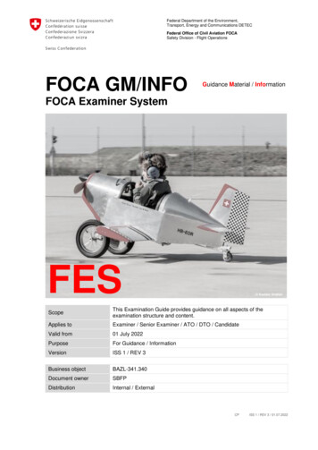
2. RDASS SYSTEM DESCRIPTIONBCDEFGH2.1 List of ComponentsTable 1: RDASS Basic ComponentsDescriptionPartNumberItemQtyA1B1C2Flight Battery57605014DCAnti-Crush Tubes27606044Pelican Case withFoam57605018HiTec Charger576050217
QtyE.11HDMI RibbonCable17606427E.2HD-2SD-1Video Antenna17606701F1Radio Controllerwith Charger17606135G1Video Monitor57605017H1Tripod, VideoMonitor176064018DescriptionPartNumberItem
Table 2: RDASS Maintenance Kit (Part # ter17606022-1Dynamite Drivertoolkit17606091110mmOpen/Closed EndWrench17606176J.11Spare Battery,DX9 Radio27606155K.12Spare e-Props(Right)17606024K.22Spare e-Props(Left)17606025L.11Spare RemoteTether57606010-DescriptionPartNumberItem9
Table 3: Optional amera Gimbaland PowerCable876060441Sony α6000176067161FLIR Camera176066391Gyro StabilizedDual 066021PC GroundControl Station87600008110Tablet/PCCommented [ZM1]: Update Photo
Table 3 (Continued): Optional encer1Additional VideoHDMI Out andEthernet Out1SanDisk 64 GBCard17606527112 Volt PowerSupply776100001Red and BlueStrobe176066291Red, Green,White NavigationLights576060068760601811
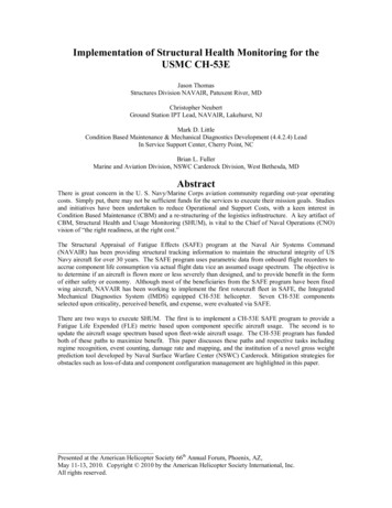
2.2 DX9 Radio Controller SwitchologyGo-Home Switch orCamera Select (for dual camera)Count-Down Timer SwitchGPS Position Hold SwitchIntelligent Orientation SwitchOn/Off SwitchGimbal PositionSelectTX7.9V10:00 0Throttle TrimYaw Trim 0 0 0Pitch (Fore)/Aft TrimLateral TrimCount-Down Timer12
01E2Aircraft Orientation ModeClimbThrottleDescendYaw LeftYaw ControlYaw RightFly ForwardPitch ControlFly RearwardFly RightRoll ControlMotor StartupMotor ShutdownFly LeftCombinedStickCommand(CSC)to start motorsHold 6seconds toshutoff motorsNote: If the operatorholds the CSCforlonger than 2 seconds themotors will shut offWarning: Releasing theThrottleprior to 6seconds can result inunintentional flight13
01E2Course Lock ModeClimbThrottleDescendYaw LeftYaw ControlYaw RightFly indirection thataircraft nose waspointing duringboot-upregardless ofcurrent aircraftorientationOrientation during boot-upPitch ControlFly indirection thataircraft tail washeading duringboot-upFly indirection thataircraft right wingwas headingduring boot-upRoll Control14Fly indirection thataircraft left wingwas headingduring boot-upCurrent aircraft headingOrientation during boot-upCurrent aircraft heading
01E2Point-of-Interest ModeRecord Point ofInterestToggle Switch 3times betweenposition 0 andposition 2 torecored Point ofInterestPurple LED will flashmultiple times to indicatea point of interest hasbeen recordedDecreases theradius of actionRadius ControlIncreases theradius of actionCircles point ofinterest in a counterclockwise directionas viewed fromaboveCircle Control01F2Circles point ofinterest in aclockwise directionas viewed fromabove0Caution: In AttitudeGPSMode the aircraft will1F2Attitude drift with the windGPS Position HoldNormalGo-Home SwitchRegain Control:Go Home15
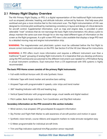
2.3 HD Video MonitorAutopilot ModeIntelligent OrientationFlight VoltageVideo SignalStrength Remote Control SignalStrengthVisible SatellitesMODE GPSOFFGoProStatus1080/30Wide23.49710014Artificial HorizonHorizonGoPro BatteryLine of Sight (LOS) to HomeOFFPointAz:201 H.S.:2.4M/S V.S.:-0.3M/SD:23.4H:MPower SwitchVertical SpeedHorizontal SpeedAircraft AzimuthDistance from HomeAircraft AltitudePoint (AGL)CAUTION16The Pilot-on-the-Controls must exercise caution whendirecting attention to the Video Monitor. Always use aVisual Observer to aid in obstacle avoidance
3. PC GROUND CONTROL STATION3.1 Ground Control Station Components3.2 Ground Control Station Procedures3.2.1 Link Ground Control Station to the Aircraft1. Attach Antenna to 900 MHz Transceiver Unit.2. Connect the 900 MHz Transceiver to a computer as shown below.Be sure to connect both the Communication and the Powerinterfaces into the computer’s USB Ports.3. In the upper right hand corner of the “GS” app select appropriateCom Port from the drop-down menu.4. Press “CONNECT”.CommunicationAntenna900 MHz TransceiverPowerCom Port drop-down menu17
3.2.2 Create a Flight Plan Using Photogrammetry ToolCamera and flight profile1. Select Photogrammetry Tool under Toolbox menu.2. Configure camera and flight profile information.3. Select Click to draw a region which you want to scanbutton4. Position box over area of interest and press Preview.a. Flight Plan will begin at yellow pin and end at redpin5. Press Generate to view flight plan in the EditorRotate Scan Region3.2.3 Create a Flight Plan Using a Template1. Select Route Template under Toolbox menu.2. Press Add Area, then position box over area ofinterest.3. To the right of desired template (e.g. Circle),enter altitude under “Alti” column and numberof points under “Par” column.4. Click button of desired template (e.g. Circle).5. Click Import to Edit List to view flight plan inthe Editor.18
3.2.4 Edit, Save, and Recall a Flight PlanTo edit a property for ALL waypoints Click on Editing Mission to edit:o Mission time limit in secondso Route – Continuous versusStart to Endo Mission Altitudeo Mission Speedo Waypoint Turn ModeTo edit a property for a single waypointClick to SaveClick to open a saved plan Click on a single waypoint to edit:o Position – Latitude & Longitudeo Altitudeo Waypoint Turn Modeo Speedo Heading (used forStopAndTurn)o Hover Time (used forStopAndTurn) To save a flight plan for future use,click the SAVE button on thebottom of the EDITOR. To recall a saved flight plan, clickthe OPEN button on the bottom ofthe EDITOR.20
4. BATTERY rgeSetting22.2 (6S)Charge Maximum ChargeRate (A) Voltage (V) Time6-825.25 40 min.LiPo11.1 (3S)6-812.65 30 min.LiPo7.4(2S)-- 3 hr.4.1 BATTERY SAFETYCAUTIONCAUTIONCAUTIONCAUTIONIf a vehicle is to be used for charging, the vehicle mustbe running for the alternator to continue to charge thecar battery. Charging a Flight Battery with a car batterycan leave you stranded if you don’t run your car.The operator should not begin a flight with less than25.0 Volts on the Flight Battery.Do not fly batteries beyond 80% of their capacity(7,200 mAh)Do not put the battery into water; store the battery in acool and dry environment.Do not use or store the battery near fire.CAUTIONOnly use provided charger to charge batteriesCAUTIONCAUTIONDo not transport or store the battery with metalobjects.21
CAUTIONCAUTIONCAUTIONCAUTIONCAUTIONCAUTIONDropping the battery can cause rupture. Avoidpuncturing battery. Do not disassemble or alter thebattery.Do not use or store the battery in extreme heatenvironments, such as direct sunlight or in a car.Overheating the battery may affect the performanceof the battery and shorten the service life of thebattery.Battery electrolyte gel can be harmful or fatal ifswallowed. Battery electrolyte gel is an eye irritant. Ifbattery ruptures, avoid getting any gel in your eyes. Ifbattery electrolyte gets in eyes, flush eyes with waterthen seek medical assistance immediately.If battery odor, battery swelling, or any other abnormalphenomena occur, discontinue use and discardbattery in accordance with local laws.Use a clean dry lint-free cloth to clean batterycontacts.Discarded battery could lead to a fire. Completelydischarge the battery and wrap the output terminalwith insulating tape before discarding. Discard batteryin accordance with local laws.Do not charge batteries unattended.CAUTIONCAUTIONCAUTION22DO NOT drain the flight battery beyond 80% or leavethe battery plugged into the RDASS when unused.Land as soon as practicable when the low voltageLED alert flashes to avoid damage to the battery,persons, or property.
4.2 CHARGING THE RADIO CONTROLLERThe DX9 has an internal charger designed to charge the included2-cell Li-Ion battery at a charge rate of 200mAh. The charge porton the right side of the transmitter is not polarity-dependent.Always charge the transmitter on a heat resistant surface.1. Power off your transmitter.2. Connect the power supply connector to the transmittercharge port.3. Connect the power supply to a power outlet using theappropriate adapter.4. The blue LED on the front of the transmitter turns on duringcharging and turns off when the battery is fully charged.5. Disconnect the transmitter from the power supply oncecharging is complete and disconnect the power supplyfrom the power outlet.CAUTIONNever connect an external battery charger to yourDX9 transmitter. If you wish to charge the Li-Ionbattery using a LiPo/ Li-Ion charger, you mustremove the battery from the transmitter beforecharging.23
4.3 CHARGING THE GOPROCharge the battery by connecting the camera to a computer orother USB charging adapter using the included USB cable. Thecamera status light turns on during charging and turns off whencharging is complete. Use on 5V 1A charger.4.4 TESTING LIPO BATTERY VOLTAGE00.0A0W- 25.32V00.0WH4.5 CHARGING SONY Α6000 BATTERY24
4.6 CHARGING LIPO FLIGHT BATTERIES1. Plug in HiTec Charger to 12-18 V Direct Current source;Select channel 1 or channel 2;2. Press “INC” to toggle to “LiPo CHARGE”. Press “Enter”3. Press “INC.” or “DEC.” to toggle Amperage. Press “Enter”4. Press “INC.” or “DEC.” to toggle Voltage. Press “Enter”5. Connect Battery to HiTec Charger6. Press and hold START for 2 seconds7. HiTec Charger Prompts “CONFIRM”. Press “Enter”R:6SER S:6SERCONFIRM (ENTER)8. Verify charge [mAh] is counting upLi6s 4.7A 23.19VCHG 022:43 00682❽mAh Charge9. After Battery charges, record charge [mAh] on Battery Log -Power Input❶Channel Select❷LiPo CHARGELiPo6.0ACHARGE22.2V (6S)LiPo6.0ACHARGE22.2V (6S)❸Amperage❹Voltage“INC” to toggle❻START❼ENTER25
4.7 CHARGING THE VIDEO MONITOR1. Plug in HiTec Charger to 12-18 V Direct Current source;Select appropriate channel;2. Press “INC” to toggle to “LiPo CHARGE”. Press “Enter”3. Press “INC.” or “DEC.” to toggle Amperage. Press “Enter”4. Press “INC.” or “DEC.” to toggle Voltage. Press “Enter”5. Connect Video Monitor to HiTec Charger6. Press and hold START for 2 seconds7. HiTec Charger Prompts “CONFIRM”. Press “Enter”R:3SER S:3SERCONFIRM (ENTER)8. Verify charge [mAh] is counting upLi3s 4.7A 10.16VCHG 022:43 00682❽mAh Charge1Power Input -❶Channel Select❷LiPo CHARGELiPo6.0ACHARGE11.1V (3S)LiPo6.0ACHARGE11.1V (3S)❸Amperage❹Voltage“INC” to toggle26❻START❼ENTER
4.8 LIPO BATTERY STORAGE PROCEDURES1. Plug in HiTec Charger to 12-18 V Direct Current source;Select appropriate channel;2. Press “INC” to toggle to “LiPo STORAGE”. Press “Enter”3. Press “INC.” or “DEC.” to toggle Amperage. Press “Enter”4. Press “INC.” or “DEC.” to toggle Voltage. Press “Enter”5. Connect Ground Station to HiTec Charger6. Press and hold START for 2 seconds7. HiTec Charger Prompts “CONFIRM”. Press “Enter”R:6SER S:6SERCONFIRM (ENTER)8. Verify charge [mAh] is counting upLi6s 4.7A 23.19VSTO 022:43 00682❽mAh Charge -Power Input❶Channel Select❷LiPo CHARGELiPo6.0ASTORAGE22.2V (6S)LiPo.0ASTORAGE22.2V (6S)❸Amperage❹Voltage“INC” to toggle❻START❼ENTER27
5. Cameras5.1 GoPro Hero41. Camera Status Light (red)2. Shutter/Select Button3. Wireless Status Light (blue)4. Camera Status Screen5. Power/Mode Button11. HERO Port13. Battery Door286. Micro HDMI Port (cable not included)7. micro SD Card Slot (micro SD card notincluded)8. Mini-USB Port (supports compositeA/V cable/3.5mm stereo mic adapter,not included)9. Audio Alert10. Microphone12. Settings/Tag Button
5.1.1 Common GoPro Operations5.1.2 Take Time Lapse PhotosTIMELAPSEx2EXITx5EXITTake Time Lapse VideoTIMELAPSECapture Time Interval Stills While Recording VideoVID PHOTOAdjust Video Resolutionx6EXITAdjust Photo Resolution5.1.3 GoPro Camera SpecificationsSensor Size1/2.3-inch type 4:3 sensorswith 4,000 x 3,000 pixelsField-of-ViewVertical4 x 3 Wide94.4 4 x 3 Medium72.2 4 x 3 Narrow49.1 17 x 9 Wide69.5 16 x 9 Wide69.5 16 x 9 Medium55 16 x 9 Narrow37.2 Horizontal122.6 94.4 64.6 125.3 118.2 94.4 64.4 29
5.1.4 GoPro Hero4 MenusGOPRO MODESVIDEO MODESVIDEO SETTINGSPHOTO MODESPHOTO SETTINGSPROTUNE SUB-MENU30
SETUP MODE5.1.5 GoPro Status ScreenCamera Modes /Field of ViewResolutionCamera SettingsFrames/sec.Protune Battery Life# of Files CapturedTime/Storage/FilesWi-Fi31
5.2 FLIR Vue and FLIR Vue Pro5.2.1 FLIR Vue and FLIR Vue Pro Specifications Polarity Control (Black Hot/White Hot) and Color Palettescan be adjusted using the Camera Controller GUIapplication on a computer. For FLIR Vue Pro a mobile appis available.Do not touch the lens. If the lens gets dirty, a light dustingof air should dislodge any dust particles. If the lens is stillnoticeably dirty, use 75% isopropyl alcohol and lens tissue.Use a light wiping motions with a fresh section of lenstissue with each swipe so as not to drag dust or dirtparticles back over the lens surface.FLIR Vue is neither water nor dust resistant. Care for it asyou would any valuable piece of electronics equipment.Thermal ImagerResolutionLens OptionSpectral BandFull Frame RatesExportable Frame RatesSizeWeightInput Supply voltagePower Dissipation, steadystate (max 2.5 W duringshutter event ofapproximately 0.5 seconds)Operating TemperatureRangeNon-OperatingTemperature RangeOperational Altitude32Uncooled VOx Microbolometer640 x 5129 mm; 69 x 56 13 mm; 45 x 37 19 mm; 32 x 26 7.5 μm – 13.5 μm30 Hz (NTSC); 25 Hz (PAL) US only, notfor Export7.5 Hz (NTSC); 8.3 Hz (PAL)2.26” x 1.75” (57.4 mm x 44.5 mm)(including lens)3.25 oz. to 4.0 oz. (92.1 g to 113.4 g)configuration dependent4.0 VDC – 6.0 VDC 1.2 W-20 C to 50 C-55 C to 95 C40,000 feet
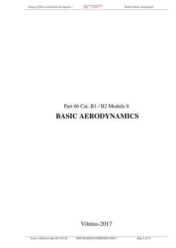
5.3 Sony α6000Rear View123456789101112Multi interface shoeImage sensor positionmarkHook for shoulder strapWi-Fi sensor (built-in)FlashMode dialControl dialCharge lampMulti/Micro USB TerminalHDMI micro jackEye sensorViewfinder1314Eyepiece cupLCD screen151617181920212223Diopter-adjustment dial(Flash pop-up) buttonMENU buttonAEL button / Playback zoomMOVIE (Movie) buttonFn (Function) button / Send to SmartphoneControl wheelC2 (Custom 2) button/ (Delete) button(Playback) button33
Front View12345678Bottom ViewShutter buttonC1 (Custom 1) buttonRemote sensorON/OFF (Power) switchSelf-timer lamp/AF illuminatorLens release buttonMicrophoneLens123456789NFC functionConnection plate coverTripod socket holeSpeakerAccess lampBattery/memory card coverMemory card slotBattery insertion slotBattery eject lever5.3.1 Sony α6000 Camera SpecificationsSensorField-of-ViewFor 20mm lens34Image sensor: APS-C format (23.5 mm 15.6 mm) CMOS image sensorTotal pixel number of image sensor:Approx. 24,700,000 pixelsEffective pixel number of camera:Approx. 24,300,000 pixelsVerticalHorizontal40.8 58.5
5.4 MicaSense RedEdge5.4.1 MicaSense RedEdge Camera SpecificationsSensorsBand 1Band 2Band 3Band 4Band 5Field-of-View4.8 mm x 3.6 mm , 1280 x 960 Global ShutterFocal length: 5.5 mmAspect Ratio: 4:3Blue FilterGreen FilterRed FilterNear IR FilterRed EdgeVerticalHorizontal36.2 47.1 35
5.5 Additional Ethernet Out1. Install the antennas on the Lightbridge2. Connect the HDMI Out on the Lightbridge to the HDMI inon the Matrox.3. Plug Matrox, Lightbridge, and up-scaler (if in use) intopower.4. Tap then hold the power button on the Lightbridge to turnon (same sequence of tap then hold will turn Lightbridgeoff).5. Connect Ethernet out on Matrox to Ethernet port oncomputer.6. Place SD card in matrox if recording is desired7. Go to User Interface to complete setup.Use explorer tonavigate to169.254.1.11Go to Settings StreamUsername: adminPassword: adminSelect Steam onlyor Stream andrecord.Select SteamingType36
6. GeoReferencerThe GeoReferencer offers precision photo triggering whilerecording every capture event’s location, altitude, and directioninformation.6.1 GeoReferencer ComponentsHot Shoe Acknowledgment UnitGPS ConnectorControl ModuleSD Card SlotTrigger InputGPS AntennaManual Trigger Button6.2 Configuring the GeoReferencer To configure the GeoReferencer open the Config.txt fileand follow the instructions.If the Config.txt file is lost, install the SD card in theGeoReferencer and power the module and a newConfig.txt file will be created.37
Page Intentionally Left Blank38
7. FLIGHT PROCEDURES7.1 Course Lock Procedure The aircraft’s autopilot records the aircraft’s heading duringboot-up. This initial aircraft orientation can be used to steerthe aircraft during flight. After connecting the flight battery, the autopilot does a selfinitialization. The LED Autopilot Status Light will blink witha quick sequence of green LED flashes to indicate that thehome-point and the aircraft’s orientation have beenrecorded. Engage Course lock by moving the Intelligent OrientationSwitch to position “1”. Direction control inputs will now berelative to the aircraft’s orientation at boot-up regardless ofcurrent aircraft heading.Orientation during boot-up01E2Current aircraft heading To dis-engage Course Lock simply return the IntelligentOrientation Switch to position “0”. Direction inputs will berelative to the nose of t
horizontally of any cloud. CAUTION ONLY use Leptron provided propellers and batteries. CAUTION Keep the compass module away from magnets including car speakers. Magnets can damage the compass and can cause the aircraft to lose control. CAUTION Do not leave LiPo batteries in direct sunlight. This can reduce the life of the batteries. NOTE NOTE .