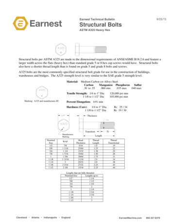
Transcription
Implementation of Structural Health Monitoring for theUSMC CH-53EJason ThomasStructures Division NAVAIR, Patuxent River, MDChristopher NeubertGround Station IPT Lead, NAVAIR, Lakehurst, NJMark D. LittleCondition Based Maintenance & Mechanical Diagnostics Development (4.4.2.4) LeadIn Service Support Center, Cherry Point, NCBrian L. FullerMarine and Aviation Division, NSWC Carderock Division, West Bethesda, MDAbstractThere is great concern in the U. S. Navy/Marine Corps aviation community regarding out-year operatingcosts. Simply put, there may not be sufficient funds for the services to execute their mission goals. Studiesand initiatives have been undertaken to reduce Operational and Support Costs, with a keen interest inCondition Based Maintenance (CBM) and a re-structuring of the logistics infrastructure. A key artifact ofCBM, Structural Health and Usage Monitoring (SHUM), is vital to the Chief of Naval Operations (CNO)vision of “the right readiness, at the right cost.”The Structural Appraisal of Fatigue Effects (SAFE) program at the Naval Air Systems Command(NAVAIR) has been providing structural tracking information to maintain the structural integrity of USNavy aircraft for over 30 years. The SAFE program uses parametric data from onboard flight recorders toaccrue component life consumption via actual flight data vice an assumed usage spectrum. The objective isto determine if an aircraft is flown more or less severely than designed, and to provide benefit in the formof either safety or economy. Although most of the beneficiaries from the SAFE program have been fixedwing aircraft, NAVAIR has been working to implement the first rotorcraft fleet in SAFE, the IntegratedMechanical Diagnostics System (IMDS) equipped CH-53E helicopter. Seven CH-53E componentsselected upon criticality, perceived benefit, and expense, were evaluated via SAFE.There are two ways to execute SHUM. The first is to implement a CH-53E SAFE program to provide aFatigue Life Expended (FLE) metric based upon component specific aircraft usage. The second is toupdate the aircraft usage spectrum based upon fleet-wide aircraft usage. The CH-53E program has fundedboth of these paths to maximize benefit. This paper discusses these paths and respective tasks includingregime recognition, event counting, damage rate and mapping, and the institution of a novel gross weightprediction tool developed by Naval Surface Warfare Center (NSWC) Carderock. Mitigation strategies forobstacles such as loss-of-data and component configuration management are highlighted in this paper.Presented at the American Helicopter Society 66th Annual Forum, Phoenix, AZ,May 11-13, 2010. Copyright 2010 by the American Helicopter Society International, Inc.All rights reserved.
IntroductionThere is great concern in the U.S.Navy/Marine Corps aviation community regardingout-year operating costs. Maintenance activitiescomprise a major portion of total ownership costsfor Navy weapon systems, with a majority of thosebeing attributed to direct maintenance costs (figure1, Ref 1).Figure 1: Maintenance Costs for the CH-53EPremature and unnecessary maintenanceare inflating maintenance costs and thereforeoverall ownership cost. The CH-53E costs moreper flight hour than a number of US Navy/MarineCorps aircraft programs (figure 2).0CH-53E MH-53E CH-53D AH-1WUH-1NCH-46E KC-130F FA-18D SH-60BFigure 2: FY04 Program Costs per Flight Hour, byT/M/SStudies and initiatives have beenundertaken to reduce Operational and Support(O&S) Costs, with a keen interest in ConditionBased Maintenance (CBM) and a re-structuring ofthe logistics infrastructure. CBM utilizes Healthand Usage Monitoring Systems (HUMS) andincludes maintenance processes and capabilitiesderived from real-time or near-real-timeassessments obtained from embedded sensorsand/or external tests and measurements using eitherportable equipment or actual inspection. Theobjective of CBM is to perform maintenance basedupon the evidence of need while ensuring safety,reliability, availability, and reduced total ownershipcost [Ref. 2 and Ref. 3]. A key artifact of CBM,Structural Health and Usage Monitoring (SHUM) isvital to the Chief of Naval Operations (CNO) visionof, “the right combat readiness for the right cost”[Ref. 4].NavalAirSystemsCommand’s(NAVAIR) answer to SHUM is the StructuralAppraisal of Fatigue Effects (SAFE) program. TheSAFE program entails using flight data recorders toidentify the severity to which the aircraft (and itscomponents) is being utilized in comparison to howit was intended and designed. The recorded usagedata is then used to monitor various fatigue criticalcomponents and/or locations on the aircraft. Theprogram can then determine how to performmaintenance based on the specific aircraft need andnot based on an assumed designed usage.BackgroundIn 1997, a team led by the program officesof the H-53 and Executive Helicopters (PMA-261)and the SH-60 Multi-mission Helicopters (PMA299) were selected to implement the GoodrichCorporation’s Integrated Mechanical Diagnostic –Health Usage and Monitoring System (IMDHUMS) on the SH-60B and CH-53E aircraft underthe Office of Secretary of Defense’s (OSD)Commercial Operations and Support SavingsInitiative (COSSI). The system evolved under theJoint Dual-Use Program Office’s (JDUPO) COSSIand is now referred to as the Integrated MechanicalDiagnostics System (IMDS) [Ref. 5].The first CH-53E was equipped withIMDS in 1998 and was soon followed by threeadditional aircraft in 1999.These initialinstallations served as data sources for acceleratedsystem characterization and service suitabilityevaluations for the remaining fleet aircraft. In 2004the IMDS successfully completed Operational Testand Evaluation (OTE) which allowed for the fullrate procurement and production of the system onthe CH-53E [Ref. 6].The NAVAIR Aircraft Structural LifeSurveillance (ASLS) branch, AIR 4.3.3.4, hastracked the structural life on Navy/Marine Corpsfixed wing aircraft via the SAFE program since the1970s. In 2006, discussion between the NAVAIRStructures Division (AIR 4.3.3), PMA-261 andPMA-275 focused on implementing SAFE on theirrespective rotary wing aircraft, the CH-53E andMV-22B, to meet the emerging CBM initiatives.
This would mark the first time SAFE wasperformedforrotarywingedaircraft.Implementation of SAFE poses several challengesto any aircraft program; the need for flight data, anaccurate gross weight association to betterincrement damage and a gapfilling methodology toaccount for missing data. In addition to theseobstacles, SAFE implementation for a rotary wingfleet introduces additional obstacles; the need toidentify the serialized dynamic component historyand an even more robust gapfilling methodology toaccount for variations in load and the fatiguecontribution due to ground rotor turn time.This paper will address the CH-53E SAFEeffort, the plans to pursue its CBM benefits, and thetechnical challenges experienced in the process.IMDSThe IMDS consists of an airborne systemand a ground based system, both implemented withan open architecture approach. The data used bythe system is obtained primarily from state sensorsthat are part of the basic aircraft (including buses),and specially mounted accelerometers and shaftposition sensors [Ref. 5]. The major functionalitiesincorporated into IMDS are Health Monitoring,Usage Monitoring, and the Maintainer Interface(figure 3).For the purpose of this paper, the primarycomponents providing data for SAFE CBM relatedactivities are the Usage Monitoring and theMaintainer Interface.Airborne SystemThe airborne system consists of theoriginal manufacture helicopter fitted withadditional hardware and instrumentation [Ref. 5and Ref. 7]. During ground and flight operations,the Main Processor Unit (MPU) acquires data atsampling rates ranging from 10 to 40 hertz, storingmost data as a 1-second averaged signal. Theairborne system can be configured to storeparametric data at a higher rate if an exceedance orevent occurs. These high-rate data are referred toas a burst data set. In the case of SHUM, someparametric data are stored at a higher rate forregime recognition [Ref. 8]. A sample list ofparameters required at higher than 1 hertz forSHUM can be found in table 1 [Ref. 9]. ParameterData Rate (Hz)Vertical Acceleration8Pilot Stick Positions (and/or8swashplate positions)Roll Rate8Rate of Climb6Engine Torque6Roll Attitude4Pitch Rate4Yaw Rate4Rotor Speed2Pitch Attitude2Airspeed2 Table 1: Minimum Data Rates for High RateStructural Monitoring Parameters.The data is written and transferred to theGround Station (GS) via a Personal ComputerMemory Card International Association (PCMCIA)card.Ground StationFIGURE 3: Subcomponent Functions to IMDSThe IMDS incorporates an InformationTechnology infrastructure made up of a series ofnetworked GS devices providing application userinterface tools that support pilot and maintaineractivities. For the purposes of SAFE, the key taskof the GS is the storage, linking, and archiving ofIMDS aircraft data. The maintainer is responsiblefor downloading the Raw Data Files (RDFs) aftereach flight, where the aircraft files are stored at thelocal level to support the IMDS application. Thefiles are copied nightly via secure socket encryptionto the Navy’s fleet archive at Naval Air Station
(NAS) Patuxent River (PAX) where they aredistributed to customer servers such as SAFE.SHUM DevelopmentThere are two ways to execute SHUM.The first is to implement a CH-53E SAFE programto provide a Fatigue Life Expended (FLE) metricbased upon specific aircraft usage exhibited on eachserialized dynamic component or airframe location.The second is to update the aircraft usage spectrumbased upon fleet-wide aircraft usage and then adjustcomponent retirement times. The CH-53E programoffice has funded both of these paths to maximizebenefit. The following discusses the processesneeded to achieve these goals.The SAFE SystemThe SAFE system requires the followingfleet data: IMDS flight data Pilot recorded flight records Aircraft dynamic component configurationrecords (figure 4).These data are processed to perform: Regime Recognition Serialized Component DamageThe output of the SAFE system is the SAFE report,which in part contains a component life expendedsummary of all serialized life limited fleetcomponent.IMDS Aircraft DataOnce the fleet maintainers download thedata to the ground based system, the data file isthen sent to the local squadron archiveautomatically. The data file is then sent to theIMDS fleet archive and subsequently to the SAFEserver on a nightly basis. This process is run via abatch file. The batch file checks the IMDS RDFfilename to determine if it is a new file or not.Embedded in the filename is the aircraft tailnumber, aircraft type, the download date anddownload time. These artifacts are important, asthey are used to match up IMDS data with aircraftflight and configuration records. Once a file isretrieved and stored, the data are kept indefinitelyin the event reprocessing is ever required.Pilot Flight RecordsThe squadrons are required to provideflight records for every flight. After each flight, thepilot enters the flight date, flight duration, and otherinformation into the flight record trackingapplication.These data are referred to asMaintenance, Material, and Management (3M)records.The 3M records are compared tosubmitted RDFs to determine if any flight data filesare missing.In the event that an RDF does not have anaccompanying 3M record, or a 3M record does nothave a matched RDF file, the squadron is contactedto avoid data loss. Until the discrepancy isrectified, the data is deemed missing. All missingdata needs to be gapfilled to account for fatiguedamage incurred on flights in which there is noIMDS data. Gapfill methodology will be discussedlater in this paper.Aircraft ComponentConfigurationFigure 4: The SAFE ProcessThe last piece of data provided by thesquadrons is the dynamic component configurationdata.These records reside in the Navy’sconfiguration management application, theOptimized Organizational Maintenance ActivityNaval Aviation Logistics Command ManagementInformation System (OOMA-NALCOMIS) and arecompiled from Assembly Service Record (ASR)cards, Equipment History Record (EHR) cards andService Removal Component (SRC) cards. Thesecards document when a particular serial number ofa specific part number is removed from one aircraftand placed on another aircraft, moved to storage,
repaired, overhauled, and/or retired. The fleetmaintainer selects preloaded part numbers inOOMA-NALCOMIS and moves them betweenaircraft via Work Unit Codes (WUCs).These configuration data are entered by allsquadrons and then replicated to the OOMANALCOMIS top tier server. These configurationdata are pulled by the SAFE process nightly andquality controlled with any available data that mayhave been previously received. These records arethen compiled to identify which serial number wasinstalled on which aircraft for what time period.The SAFE process can then identify which RDFdata to assign to which component.It is important to note that the SAFEquality control process has uncovered occasionswhere the incorrect serial numbers or aircraft tailnumbers were assigned to a component. TheOOMA-NALCOMIS record sub-system does nothave an efficient process to notify the squadrons ofdiscrepant records. Some discrepancies identifiedby the SAFE quality control process are: incorrectamount of expected parts installed on one aircraft,same serialized component on two differentaircraft, and time since new (TSN) data is reset tozero when a component is reinstalled on aircraft.Compiling complete and accurate componenthistory data remains the most difficult task fortracking fatigue life of serialized components inSAFE.SAFE ProcessingWith the above data at the SAFE server,processing of the three types of data is performedwith the end product being damage assessments ofevery life limited, serialized component.Regime RecognitionRegime Recognition (RR) is a process inwhich known flight maneuvers are identified fromparametric flight data. These identified flightmaneuvers (or regimes) have fatigue damage valuesassociated with them depending on the parametricvalues. The RR code processes through 6 stages asit identifies the 356 known flight regimes of theCH-53E and categorizes them into 78 fatiguedamaging regimes.The first stage addresses the fact that mostparameters used for structural tracking are recordedat different rates; some as low as 1 Hz, while othersare recorded at up to 10 Hz. Whether due to IMDSlimitations or data storage concerns, some data arerecorded at less than optimum frequencies forSHUM; however the minimum frequencies are met.Data that is recorded at less than 10 Hz isinterpolated between the maximum and minimumvalues in that range to create parametric records at10 Hz. Should an event where a data spike ordropout occur, the data is interpolated to avoidgapfilling. Most occurrences of this are no morethan 2 seconds and within the limit forinterpolation.The second stage in the RR process is tolump like regimes that occur sequentially together.The third stage in RR is the consolidationlogic. This portion of the code looks at the recentlylumped regimes and determines how long themaneuver lasted. This allows compression andbetter damage mapping so that instead of 20records stating the same regime, there is one 2second record with the flight regime. Anotherbenefit of the consolidation code is whenparametric data of certain maneuvers border thethreshold limits. Since it is possible that the RRcode could identify different transient regimes forone maneuver based on where the parametricthresholds are set, the consolidation code has logicbuilt in that identifies the actual maneuveroccurring and lumps the like data together. Forinstance, this would cause a maneuver sequence tobe counted as a 30 degree angle of bank turn for 3seconds, even if the parametric data causes the RRcode to identify it as a 30 degree turn followed by a1.1 g pullup followed by a second 30 degree angleof bank turn. This is also a benefit whereindividual pilot technique may influence the data.The fourth stage in the RR code is toidentify all control reversals, their start time andduration. A control reversal is when a pilot inputscontrol completely in one direction, then fullyreverses the input to the opposite direction. Theaircraft weight is also used here to determine thedamage increment incurred by the control reversals.The control reversal damage increment is onlycounted once and is not double counted when theRR process is complete.The fifth stage is to identify all otherdamaging maneuvers that are counted based on thenumber of occurrences and not duration. Examplesof such maneuvers are Ground-Air-Ground (GAG)cycles, hook loads, and torque cycles. The finalstage for the RR code is the log file. The log fileprovides basic results on the quality assuranceprogram. The log file records takeoffs, landings,rotor start and stop conditions, and the cause forflight rejection, if applicable.The RR code was validated against flighttest data, known as the ‘HUMS flights’. TheHUMS flights were a number of flights in whichpilots flew to a known sequence of regimes atspecific times. The RR code was then validated by
producing the expected results from the HUMSflights.Once the RDF file is processed throughthe RR code, an output file is generated and aregime identifier is assigned to all regimes locatedin the file. This output file summarizes all theregimes that occurred in the RDF, as well as thetime and duration of the regime.Gross Weight EstimationAs depicted in figure 5, componentdamage rates are impacted by aircraft gross weight(GW) and altitude. Without accurate gross weightestimation, the most conservative damageassumption must be utilized. In order to accuratelymonitor gross weight, IMDS requires crew inputbefore a flight. This is deemed an impracticalincrease to pilot workload as well as a source ofpotential inaccuracy.hovers are infrequent with no way to measureairspeed and given that drag is difficult to accountfor in the higher speed regimes, this improvement issignificant. In contrast, the new virtual sensorutilizes an energy approach to determine the grossweight at take-off by essentially calculating theintegral of the engine torque and equating thisquantity to the energy necessary to lift a givenweight (in this case, the aircraft gross weight) to aprescribed altitude (in this case, 30 ft) in a finiteamount of time that is related to both the energyinput into the system as well as the weight of thebody. Other than time and torque, the other inputsto the model are pitch attitude and density altitude(to account for air temperature and air pressure).The sensor currently operates during post flightanalysis which allows the reconstruction of weightthroughout the flight. Sample virtual sensorperformance is shown with each take-offrepresented with a circle (figure 6).F lig h t 2 4 W e ig h t R e co n stru c tio n 10,000 6,00055000W e ig h t R e c o n s tru c te dW e ig h t R e c o rd e dV irtu a l S e n s o r P re d ic tio n54000ALTITUDE53000 6,000 3,00052000Aircraft G ross W eight (lbs)51000 3,000GroundLightMediumHeavyGROSS 041000400000200040006000800010 0 0 0120001 4 0 00T im e (s e c )Figure 5: Gross Weight vs. AltitudeFigure 6: Predicted vs. Actual Gross WeightThis initiated the need for a CH-53Especific Gross Weight Virtual Sensor.Theprogram funded Naval Surface Warfare Center(NSWC) Carderock to develop a novel GW VirtualSensor, similar to the one developed for the SH60B [Ref. 10], based on recorded parametricHUMS data. In order to accomplish this task,NSWC Carderock gathered flight control systemdata, weight and balance reports, Naval AviationTraining and Operating Procedures Standardization(NATOPS), and OEM reports. The GW VirtualSensor is a second generation sensor developed topredict aircraft gross weight at take-off once theaircraft has climbed to 30 ft above ground level(AGL) and has a working range of 43,000 lbs to54,500 lbs. Additional test flights are needed toexpand the weight range above 54,500 lbs. Themain advantage of this sensor over first generationsensors is that it is no longer restricted to operateduring steady hover or steady level flight. SinceDuring the 40 flights selected for modeldevelopment, weight was estimated in 38 with anaverage of 10 estimations per flight. The accuracyof the model was calculated using a five fold crossvalidation approach, one of the latest statisticaltechniques for wide data. This technique estimatesthe expected error for data not previously seen bythe sensor. This technique requires the developmentof five independent neural network models (theweight estimation is the average of the estimationfrom each of these models). Based on this analysis,the five model average has a root mean square(RMS) error of 831 lbs with a maximum overestimation of 1,900 lbs and a maximum underestimation of 2,229 lbs. The GW Virtual Sensorwas also validated against weight and balancesheets provided by PMA-261. To account for thevariation in estimation, the most conservativeweight will be used. Once the RR process is
complete and reversals identified, and the grossweight is known, the RDF can then be mapped tothe component damage table to calculate fatiguedamage.Component Damage TableGenerationThe component damage tables are a keycomponent for SHUM. The tables are from theOriginal Equipment Manufacturer (OEM), in thiscase, Sikorsky Aircraft, and represent the amount offatigue damage each component exhibits for aparticular amount of time spent in a flight regime.The table also contains damage information forthose maneuvers that are not time dependent, butrather the number of occurrences an event isrecorded.Once an RDF has been processed throughthe RR code and a gross weight identified for eachregime, the results are then mapped to the damagetables for all experienced regimes. The damagesfrom a flight of regimes are then summed toprovide a unit of damage on the components forthat flight.With no additional reliabilityadjustments, an FLE of 1.0 corresponds to end oflife for the component. This process is carried outfor all flight data to determine an FLE for all lifelimited dynamic components.Gapfill MethodologyGapfill is a process in which statisticaldata are used to fill in missing or corrupt data. Datathat are gapfilled are assumed to be more severethan average operations to account for theunknowns of the flight. Since the weight andregimes are unknown, worst case damage rates areused. Until the new fleet usage spectrum isdeveloped, gapfill rates will be based on the designspectrum at the 95th percentile for worst case. Theupdated usage spectrum will be discussed later inthis paper.Gapfill is also used when the historicalcomponent configuration data are incomplete orinaccurate. Install and removal records are onlysought for components from when IMDS wasinstalled. The starting FLE will be based on thenumber of landings and flight hours to that point.Should a serialized component have missing installor removal records, the SAFE process assumes theworst case for that time and cannot use the IMDSdata to map a fatigue damage.Due to the six-nines reliability requirement(probability of failure of a dynamic component atthe retirement life does not exceed one in a million,i.e. a reliability level of 0.999999), the gapfillmethodology will need to be revisited when thenew usage spectrum is released. One thought is touse the 99th percentile instead of 95th percentile toaccount for the perceived reduction in reliability.Many parties in industry, government and academiaare evaluating different methods to address thisnotion [Ref. 11 and Ref. 12]. For example, someproposals are to adjust the S/N curve or applyreliability factors.Components to be TrackedThe CH-53E has thirty-eight componentsthat are identified to be prime life limitedcomponents, or components with a fatigue life of10,000 flight hours or less. Once the SAFE processwas developed, the first items to be tracked neededto be determined from the existing thirty-eight.Seven of the thirty-eight life limited componentswere selected to be inducted into SAFE first, basedon criticality, perceived benefit, and expense. Thecomponents selected were: main rotor sleeveassembly, main rotor hub lower plate assembly,main rotor hub upper plate assembly, main rotorblade extender, main gear box housing, maingearbox shaft, and the main rotor spindle/sleeveassembly. The remaining thirty-one life limitedcomponents will be implemented into SAFE basedon available funding and estimated return oninvestment.Ground Station ModificationsA challenge for current SAFE programs isthe means to routinely produce real-time FLEupdates to the squadron level. Delayed delivery ofexpended life computation to squadron maintainerscan be cumbersome and requires backfilling due tothe time lag required to execute the quarterly report.The fleet user downloads the SAFE report from theASLS website on a quarterly basis. Updating themaintainers' ground stations with estimated FLEbetween published SAFE reports remains achallenge. During this time lag, the squadron mustaccrue damage to components at their mostconservative (costly) rate. This rate is the basis forthe Periodic Maintenance Information Card (PMIC)and is derived from the design spectrum. Fleetmaintainers must plan their maintenance activitiesto correspond to these rates. The CH-53E teamproposes two improvements to this scenario. First,the CH-53E OOMA configuration manager wouldimplement a simple Fatigue Life Estimatorcalculation for each component. This estimatorwill calculate damage between SAFE reports basedon statistics from existing fleet data and provide a
more accurate assessment than applying worst caseaccording to potentially obsolete design data.Second, a means to automate the SAFE reportdistribution process is being investigated includingthe use of e-mail, website downloads, andautomatic population of OOMA componentdamage fields to the users’ ground station.Usage Spectrum UpdateAnother way to gain benefit fromSHUM/SAFE is to update the aircraft flightspectrum. The initial design spectrum is usuallydeveloped in a few different ways; derivation fromspecifications such as Aeronautical Requirement 56(AR-56), pilot surveys, data on similar T/M/S orthe Navy/Marine Corps-provided requirements tothe OEM. These requirements illustrate what theexpected mission and mission mix will be for theaircraft.These requirements yield a designspectrum that drives component usage based onaircraft mission, weight, and mission frequency.During operation, it is common that any one ofthese aspects change, resulting in an inaccurateportrayal of maintenance requirements andcomponent life. A flight spectrum based on actualaircraft usage, the usage spectrum, provides a moreaccurate account of what the dynamic componentsand aircraft structure are experiencing. From thesedata, fatigue rates and maintenance intervals couldbe adjusted accordingly. In order to maximizeSHUM benefit, the CH-53E program will updatethe usage spectrum, in addition to providing SAFEFLEs.As of the writing of this paper, the CH53E usage spectrum method is still underdevelopment, however the process will be similarto that used on the Navy AH-1W in the 1990’s toupdate their usage spectrum, using statisticalcumulative frequency distribution of the usages[Ref. 13]. Traditionally, the usage spectra updateshave been through usage surveys conducted using apaper questionnaire, which is filled out by the pilotsfor information on mission type, gross weight,altitude, velocity, flight maneuver and associatedtime, flight duration, and other information. Aswith the H-1’s in the past, pilot surveys were notused for two main reasons, the pilot’s account is notalways a clear representation of the actual missionflown, and the availability or an established regimerecognition algorithm to identify the experiencedflight regimes [Ref. 13]. The CH-53E will be usingthe IMDS data and their regime recognitionsoftware to identify which regimes were flown, thedurations, and remaining information to accuratelymodel the usage.The CH-53E has benefitted from newrequirements for HUMS from lessons learned onprevious aircraft. These new requirements areoutlined in Reference 8. For usage spectrumdevelopment, 356 recognized regimes werecondensed into 78 design spectrum regimes at 3gross weights. NAVAIR has recommended havingat least 150-200 data hours for 15-20 aircraft beforefluctuations in individual operation stabilizes to afleet usage. This is dependent on having sufficientdata in each regime and to ensure all regimes areaccounted for. This should not be an issue for theCH-53E program since many IMDS were installedin 2006 and have been in operation since. SAFEstandup is scheduled for later this year.ConclusionsSAFE is a large part of SHUM and theoverall CBM program being pursued by the USNavy/Marine Corps. With the implementation ofSAFE, the CH-53E program hopes to achieve costsavings while ensuring safety is not compromised.Other studies have shown that smaller programshave been able to achieve 50% increase incomponent life using SAFE. Initial analysis hasshown that if the CH-53E program achieves 2550% savings in retirement time or maintenanceburden, the program could save in theneighborhood of 20M per year.AcknowledgementsThe authors would like to acknowledgeCapt. Richard Muldoon and Ms. Vicki Nagle ofPMA-261 for their continued efforts in initiating,developing and establishing CBM for the H-53.References[1] Croisetiere, Col P., “CH-53 Heavy LiftHelicopter Program,” Military Aviation Repair andMaintenance 2006 Conference, Arlington, VA,April 24-25, 2006[2] Condition-Based Maintenance (CBM) Pol
Pilot Flight Records The squadrons are required to provide flight records for every flight. After each flight, the pilot enters the flight date, flight duration, and other information into the flight record tracking application. These data are referred to as Maintenance, Material, and Management (3M) records. The 3M records are compared to