Transcription
Aircraft Configuration and Flight Crew Compliance withProcedures While Conducting Flight deck based IntervalManagement (FIM) OperationsRick Shay1, Kurt Swieringa2, and Brian Baxley3NASA Langley Research Center, Hampton, VA, 23681Flight deck based Interval Management (FIM) applications using ADS-B are beingdeveloped to improve both the safety and capacity of the National Airspace System (NAS).FIM is expected to improve the safety and efficiency of the NAS by giving pilots thetechnology and procedures to precisely achieve an interval behind the preceding aircraft bya specific point. Concurrently but independently, Optimized Profile Descents (OPD) arebeing developed to help reduce fuel consumption and noise, however, the range of speedsavailable when flying an OPD results in a decrease in the delivery precision of aircraft to therunway. This requires the addition of a spacing buffer between aircraft, reducing systemthroughput. FIM addresses this problem by providing pilots with speed guidance to achievea precise interval behind another aircraft, even while flying optimized descents. The IntervalManagement with Spacing to Parallel Dependent Runways (IMSPiDR) human-in-the-loopexperiment employed 24 commercial pilots to explore the use of FIM equipment to conductspacing operations behind two aircraft arriving to parallel runways, while flying an OPDduring high-density operations. This paper describes the impact of variations in pilotoperations; in particular configuring the aircraft, their compliance with FIM operatingprocedures, and their response to changes of the FIM speed. An example of the displayedFIM speeds used incorrectly by a pilot is also discussed. Finally, this paper examines therelationship between achieving airline operational goals for individual aircraft and the needfor ATC to deliver aircraft to the runway with greater precision. The results show thataircraft can fly an OPD and conduct FIM operations to dependent parallel runways,enabling operational goals to be achieved efficiently while maintaining system SCDACDTICPDLCDTGDTSEICAS Automatic Dependent Surveillance-BroadcastAssigned Spacing GoalAirborne Spacing for Terminal Area Routes (Version 10)Aircraft Simulation for Traffic Operations ResearchAir Traffic Operations LaboratoryAirspace and Traffic Operations simulationContinuous Descent ArrivalCockpit Display of Traffic InformationController-Pilot Datalink CommunicationDistance-To-GoDevelopment and Test SimulatorEngine Indicating and Crew Alerting System1Aviation Consultant, President, Double Black Aviation Technology L.L.C., Littleton CO, AIAA Senior Member.Research Engineer, Crew Systems and Aviation Operations Branch, NASA LaRC, MS 152, SS.3Research Engineer, Crew Systems and Aviation Operations Branch, NASA LaRC, AIAA Senior Member.21American Institute of Aeronautics and Astronautics
CDUMCPNDOPDPFDRTARTCARUC-13TODTTGVNAV Final Approach SpeedFlight deck based Interval ManagementFlight Management ComputerFlight Management SystemGround based Interval ManagementGlobal Operational Data Link DocumentHuman-In-The-LoopIntegration Flight DeckInterval Management with Spacing to Parallel Dependent Runways experimentDallas Love FieldDallas Fort-Worth airportLateral NavigationMulti Aircraft Control SystemMulti-Function Control Display UnitMode Control PanelNavigation DisplayOptimized Profile DescentPrimary Flight DisplayRequired Time of ArrivalRadio Technical Commission for AeronauticsRandom Update Cycle (13 kilometer resolution)Top of DescentTime-To-GoVertical NavigationI. IntroductionA. The Development of Flight deck Interval ManagementThe Federal Aviation Administration (FAA) forecasts commercial aviation will grow on average 3.7% per yearover the next twenty years, with the number of revenue passenger miles to double by 2031.1 As one method ofaccommodating this expected growth and improving the safety of operations, NASA and the FAA arecollaboratively developing a concept of operations called Flight deck based Interval Management (FIM).2,3 Thedevelopment of FIM technologies is an international effort that will enable any Air Navigation Service Provider(ANSP) to assign FIM equipped aircraft a precise interval that can be achieved behind another aircraft. FIM is asuite of functional capabilities that can be combined to improve both the safety and efficiency of flight operations.During FIM operations, the Air Traffic Controller (ATC) retains the responsibility for maintaining safeseparation between aircraft. ATC uses Ground based Interval Management (GIM) equipment to determine an arrivalschedule that includes the spacing interval pilots need to achieve, permitting ATC to assign the spacing clearance toproperly equipped aircraft. Pilots will then use FIM equipment to achieve the interval assigned by ATC. FIMoperations utilize the Global Positioning System (GPS) data, Automatic Dependent Surveillance - Broadcast (ADSB) data, onboard navigational data, and algorithms to achieve the spacing between aircraft. The FIM equipment usesthis data to provide the proper guidance for speed deviations from the nominal profile, allowing the aircraft toachieve its ATC assigned spacing interval. The spacing task described in this paper is based on using speed controlto achieve the desired interval behind preceding aircraft arriving to dependent parallel runways.In addition to improving safety and the landing rate at congested airports, it is important for airlines to improvethe efficiency of their operations, even when maximizing throughput is not critical. To help improve efficiency, it isdesired that every flight performs an Optimized Profile Descent (OPD) to reduce fuel consumption, noise, andemissions. The ideal speed for an OPD can vary considerably based on the aircraft type, aircraft weight, and wind.Furthermore, the airline may wish to modify this speed to improve schedule reliability or to improve fuel efficiency.FIM is designed to have the aircraft operate with small deviations from their OPD, while meeting the schedulerequired for high-density operations. This paper examines the competing interests between reducing fuelconsumption, achieving airline operational goals for individual aircraft, and the need for ATC to deliver aircraft tothe runway with greater precision.2American Institute of Aeronautics and Astronautics
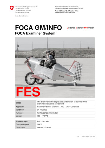
B. FIM Research on Dependent Parallel Runway OperationsPrevious NASA research of FIM to independent runway operations has shown pilots are able to conduct theseFIM operations, and arrive at the runway threshold within 5 seconds of the ATC assigned spacing interval.4 Ongoingwork by the FAA has led to a safety analysis, a description of procedures, and a description of requirements for FIMoperations in a complex terminal environment to a single runway.5 More recently, the FIM concept has beenexpanded to accommodate parallel dependent runway operations,6 and a new version of the Airborne Spacing forTerminal Arrival Routes (ASTAR) algorithm created to meet the unique requirements for these operations(ASTAR10).7 A Human-In-The-Loop (HITL) experiment called Interval Management with Spacing for ParallelDependent Runways (IMSPiDR) was conducted at NASA Langley Research Center in the summer of 2011. Thisexperiment explored the concept, and indicated, within certain constraints and conditions, that pilots are able toconduct FIM operations.8,9,10 In addition to the additional aircraft spacing requirements for dependent parallelrunway operations, the IMSPiDR experiment employed OPDs to determine if aircraft operators could use smallspeed deviations from the optimal profile to correct spacing errors, allowing the use of OPDs in a high densityenvironment.Dependent runway operations have specific separation requirements for aircraft operating on approaches toparallel runways. These requirements are based on the distance between the parallel runways. For runways laterallyseparated by more than 4,300 feet, a minimum separation of 2 NM distance must be maintained between aircraft onparallel approaches (Figure 1). The minimum separation between aircraft arriving to the same runway (the in-trailwake separation) depends on the weight class of both aircraft.Operational efficiency is a multi-faceted problem. Although fuel is a major cost factor for airlines, the cost ofequipment, the cost of labor, and the need to ensure passengers and cargo can make their connections also factor intothe efficiency of operations. As a result, achieving highoperational rates and improving efficiency whilemaintaining or improving safety is important for airlines.During operations today, an OPD allows the flight crewthe flexibility to efficiently achieve their operationalgoals, up until a speed instruction is issued by ATC. WhenFIM capabilities are added to an OPD operation, the pilotshave the ability to fly their original OPD profile until it isnecessary to adjust their speed to meet the ATC assignedspacing interval with aircraft landing ahead of them. Oneof the design goals of FIM is to have the cost of thesespeed changes generated onboard the aircraft to be smallerthan the cost of complying with ATC issued speedinstructions. This is achieved by making small speeddeviations from the nominal profile over the course of thearrival, decreasing the need for vectoring and large speeddeviations to achieve the ATC assigned spacing interval.This paper describes some of the characteristicbehaviors of FIM operations, and the impact on thisoperation caused by how the pilots configured theiraircraft, and by how well the pilot conforms to the FIMprocedures. Both quantitative and qualitative data wascollected from the experiment, including aircraft statedata, FIM performance data, questionnaires, and data fromverbal debriefs. Qualitative results pertaining to the flightcrew’s compliance with the training they received, thetimeliness of their responses to speed changes, and otherissues raised by the subject pilots are also discussed.Figure 1. Separation Criteria.3American Institute of Aeronautics and Astronautics
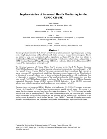
II. Experiment MethodA. Experiment BackgroundThe IMSPiDR experiment was created to investigate the FIM control algorithm to support dependent parallelrunway operations during high density throughput conditions, and the pilot procedures to conduct them in thepresence of different sources of error. Objectives of this experiment included delivering aircraft to the runwaythreshold with precision, ensuring the stability of aircraft arrival streams, ensuring pilot workload remainedacceptable, and identifying potential operational issues of the FIM concept. Scenarios and parameters were selectedto test the spacing algorithm and pilot procedures under stressful conditions (steep high-energy OPDs, complexCPDLC messages, a non-ideal CPDLC interface, high traffic volume, large perturbations, etc.). Some of theseconditions and interfaces may not be representative of an ideal implementation of FIM.The operational goal of FIM during this experiment was the precise delivery of aircraft at the runway thresholdbehind the preceding (Target) aircraft. This experiment used 24 current commercial pilots to fly OPD arrivals intothe Dallas Fort-Worth (KDFW) airport. Pilots were asked to follow onboard guidance to precisely space theiraircraft behind a preceding aircraft in one of three different types of simulators at the NASA Langley ResearchCenter. Each simulator type contained slightly different hardware and interfaces, enabling the evaluation of differentaircraft equipage levels and different pilot procedures.B. Experiment DescriptionA schedule of arrival times for all aircraft arriving into KDFW was assumed for each scenario, and it establishedthe arrival sequence and spacing interval between each pair of aircraft at the runway threshold. Either a RequiredTime of Arrival (RTA) or an RTA and FIM (RTA FIM) clearance was issued by ATC to the pilots after the start ofeach scenario and prior to Top Of Descent (TOD). Controller-Pilot Data Link Communication (CPDLC) was used toissue and respond to these clearances. After receiving the clearance via CPDLC, the pilots followed currentoperational Data Communication procedures to ‘auto-load’ the clearance into the FIM spacing tool, evaluate thecalculated FIM speed, and then accept or reject the clearances via CPDLC. After sending the CPDLC acceptmessage, the pilots were required to execute the FIM operation, causing FIM guidance to appear on the aircraft’sdisplays. If the aircraft had received a RTA FIM clearance and was out of ADS-B range from its lead aircraft, theFIM avionics provided pilots with speeds to achieve an RTA at the runway. Once the Target aircraft was withinADS-B range, ASTAR transitioned from achieving a precise time at the runway (RTA mode) to achieving a preciseinterval behind the Target aircraft (FIM mode).Since the aircraft in this experiment had two Target aircraft, the FIM speed was calculated by the ASTAR10algorithm to meet or exceed the Assigned Spacing Goal (ASG) for both Target aircraft. The ASG can be specified asa time or distance, and is the interval behind the Target aircraft that is to be achieved relative to the runwaythreshold. For IMSPiDR, time (in seconds) was used as an additional measure of clarity for the pilots when spacingbehind a Target aircraft to the same runway; distance (in nautical miles) was used when spacing behind a Target tothe parallel runway. When valid ADS-B position data for both aircraft is available, the error to achieve both spacingintervals is calculated, but the FIM speed displayed to the crew is based on the ‘controlling aircraft’. The‘controlling aircraft’ is the Target that places the FIM aircraft farthest aft, thereby ensuring both ASGs are met orexceeded.C. Operational EnvironmentFourteen different arrivals were developed into KDFW by laterally overlaying existing arrival routes andremoving most altitude constraints (approach constraints were retained) and creating the steepest angle consideredacceptable by the FAA’s Terminal Area Route Generation, Evaluation, and Traffic Simulation (TARGETS)software. These arrivals were designed to emulate OPDs that connected to an instrument approach to Runway 17Center or 18 Right (south flow operations at KDFW). Subject pilots flew the Masty, Bonham, or Cedar Creekcharted OPDs to the ILS to Runway 17 Center while following FIM speed guidance. Pilots optimized the chartedprofile by allowing the FMS to determine the proper top of descent for the aircraft weight and actual winds.Each scenario contained 35 aircraft arriving into KDFW, with an additional 25 aircraft departing KDFW and 4aircraft arriving to Dallas Love Field (KDAL). The initial position, callsign, route, altitude, and arrival sequence forall 64 aircraft were identical during the ten data collection runs, with the six aircraft flown by subject pilotsinitialized in the middle of the arrival stream (shown as magenta arrows in Figure 2).4American Institute of Aeronautics and Astronautics
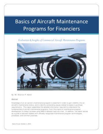
Each scenarrio initialized the subject piilots ato ne of the posiitions shown aas a magenta arrow.FFor ease of idenntification, the six aircraft floown bysuubject pilots uused a NASAA callsign. Arrrivingaiircraft not flowwn by subject pilots were opperateduusing automated ASTOR stattions (aircraft on theGGlen Rose landding on Runwway 18R, aircrraft onthhe Bowie landding Runway 118R, and aircrraft onthhe Bowie landding at KDAL). Aircraft deppartingKKDFW were geenerated by thhe MACS simuulationsooftware, and ththe standard deeparture routess weremmodified slighttly to provide visual traffic to thep ilots in the fulll-scale simulattors.Figgure 2. KDFWW Arrival Rouutes and Initiaal Position.D. Experiiment Apparaatusators1. SimulaIMSPiDDR used threee different simmulation platfoorms to explorre different FIIM equipment configurationns, anddifferent FIMFpilot proceedures. All of the simulationn platforms hadd comparable flight deck components inclluding:aircraft andd engine modeels, autopilot anda auto-throtttle systems, Fllight Managemment System (FFMS), MultifuunctionControl Diisplay Unit (MCDU), Mode ControlCPanel (MCP),(Electroonic Flight Insstrumentation SSystem (EFIS), PFD,ND, Enginne Indication anda Crew Alerrting System displayd(EICAAS), CPDLC, aand the standaard communicaations.Additionallly, each simullation platformm contained addvanced technoology componeents, includingg Cockpit Dispplay ofTraffic Infformation (CDTTI), and FIM controls and inddications.Figure 3. ClockwiseCfroom the bottomm left: (a) Deveelopment and Test Simulatoor (DTS), (b) AAircraft Simuulationfor Traaffic Operations Research (AASTOR) (c) IIntegration Fliight Deck (IFDD).The first simulator ussed in the IMSPiDR experimment was the Deevelopment annd Test Simulaator (DTS). The DTSis a full-sccale simulatorr representativee of a large commercialctraansport categoory aircraft (Fiigure 3a). Thee DTSrequires twwo pilots to opeerate and has a 210 horizonntal by 45 verttical out the wiindow field off view. It is equuippedwith eightt D-Sized dispplays, sidestick controls, ruudder pedals, two color Coontrol Displayy Units (CDUU), and5Americcan Institute off Aeronautics aand Astronautiics
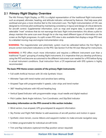
additional interface devicesderived from a variety of othertransport aircraft. The visualdisplay was the KDFW terminalenvironment and all aircrafttraffic in a daytime setting.Thesecondsimulationplatform was located within s the Airspace and TrafficOperations Simulation (ATOS)platform and the Multi AircraftControl System (MACS). ATOSis a network of AircraftSimulationforTrafficOperations Research (ASTOR)computer stations with two videomonitors,equippedwithexperimental cockpit displaysand pilot interfaces operated by asingle pilot or software logicknown as ‘Pilot Model’ (FigureFigure 4. ASTOR Navigation Display.3b). Components include: a sixdegrees of freedom equations ofmotion aircraft model, PFD, ND, autopilot, auto-throttle, FMS, MCDU, MCP, CPDLC, ADS-B, and ASTAR10.The third simulator used in the IMSPiDR experiment was the Integration Flight Deck (IFD). The IFD is a fullscale, high-fidelity simulator of a large commercial transport aircraft with standard operational instruments (Figure3c). The cockpit’s visual system is a panorama system that provides 200 horizontal by 40 vertical field-of-view.The IFD visual scene is identical with the DTS.2. FIM Displays on PFD and NDFor this experiment, FIM displays were integrated with normal aircraft displays. FIM speed guidance was placedon the PFD, depictions of the Target aircraft on the ND, three new pages were added to the MCDU, and ASTARmemos and cautions were displayed on the EICAS display.The FIM displays on the PFD included the commanded end speed, a commanded speed bug, and ASTAR modes(Figure 5). The FIM commanded end speed is depicted by green numbers above the speed tape. The pilots wereinstructed to set this speed in the MCP speed window when the aircraft was in VNAV SPEED mode. Whenever aspeed change occurred, the commanded end speed was outlined by a green box for ten seconds to help pilots noticethe change. In addition to the commanded end speed, a FIM speed bug was added to the speed tape. The speed bugdepicted the FIM commanded end speed adjusted for ASTAR10’s estimation of the aircraft’s deceleration rate, andwas intended to provide the crew with a precise indication of the desired speed at any given moment. The FIM speedbug was displayed as a green bowtie (ASTOR), triangle (DTS) or line (IFD) just to the right of the speed tape.Subject pilots were instructed to configure the flaps on their aircraft as they would in normal operations and usespeed brake and throttles as necessary to remain within 5 knots of FIM commanded speed (the green speed bug orline). The speed bug on the speed tape of the PFD was sized to help the pilots meet this 5 knot limit (discussed inPilot Training section).In addition to the commanded end speed and FIM speed bug, an ASTAR mode indicator was located next to thecommanded end speed. The mode indicator shown to the right of the FIM speed on the PFD was intended to tell thepilot what mode the ASTAR10 algorithm was using to calculate the FIM commanded speed. When the ASTARmode changed, a green box appeared around the ASTAR mode indicator for ten seconds (shown as IM in the leftand right panel of Figure 5, and as FNL (final approach speed) in the center panel).6American Institute of Aeronautics and Astronautics
Figurre 5. From leftt to right, (a) ASTORAPFD,, (b) IFD PFD,, (c) DTS PFDD.The NDD on all three simulators presentedpesseentially the samme informatioon, with the DDTS and IFD usingdiamonds as the traffic symbol, and thhe ASTOR as a chevron (F igure 4). The ND enabled ppilots to monittor therelative poosition of proximate traffic, annd identify thee controlling Taarget aircraft, aand the secondd Target aircrafft. TheVNAV veertical deviatioon indicator also provides feeedback on hoow the aircrafft is conforminng to the optiimizedvertical proofile. Additionnal informationn provided on thet ND includeed: “own-ship”” callsign, Targget aircraft callsigns,ADS-B Traffic, and the LateralLNavigaation (LNAV) route.rDuring tthe one exploraatory scenario,, a FIM conformmancebox was allso added to thee ND, allowingg pilots to quicckly determine how well the sspacing operatiion was proceeeding.Three newn pages werre added to thee MCDU to suupport the FIMM operation. Thhe first page coontained informmationabout the spacingsoperatiions such as thhe ASTAR mode, achieve-byy point, the calllsigns of the leead aircraft, thhe finalapproach speedssof the lead aircraft, annd the spacingg errors. The sppacing error foor the aircraft arriving to thee samerunway waas shown as a timeterror and the spacing errror for the airccraft arriving too the parallel rrunway was deepictedas a distannce error. Thee second and thirdtFIM MCCDU pages coontained additiional informatiion about eachh leadaircraft, suuch as their FIMM goal, achievee-by point, andd route.The EIICAS display providedpadvissories, warninggs, and cautionns to the flightt crew. Cautionns indicated AASTARfaults suchh as a loss of ADS-BAdata, a lead aircraft offo path, or thaat the time erroor was excessivve. Advisoriess couldindicate that the spacing aircrafts’ path had errors, thee spacing aircrraft was off patth, or if the Taarget aircraft haad badpath informmation. The memosmwere designed to provvide the pilots with increasedd awareness off the FIM operation,and help thhem stay on traack if they deviiated too far from the commaanded speed. SSome of the meemos included a dragrequired message,ma messsage notifyingg the pilot thatt the algorithmm was constrainning the commmanded speed, and amessage thhat notified thee pilots that theey had acquiredd the ADS-B siignal from theiir lead aircraft and had transiitionedform RTA to FIM mode.Candd EICAS Displalay3. FIM ClearancesPrior too reaching Topp Of Descent (TOD), flightt crews receiveed either an RRTA or RTA FIM clearancee fromATC. Due to the complexxity of an RTAA FIM clearannce for dependeent parallel runnway operationns, CPDLC waas usedto transmitt the FIM clearrances. The conntent of the cleearance used exxisting guidancce from the staandards develoopmentwork by thhe Radio Techhnical Commisssion for Aeroonautics (RTCAA) SC-214/EUUROCAE WGG-78 - FAA woorkinggroup, andd the Global Opperational Dataa Link Documeent (GOLD).11,,12A commplete RTA FFIM clearance contained: thhe assigned ruunway, the RTTA at the runnway, a condditionalinstructionn to transition tot interval spaccing when ablee, the Target aaircraft callsignn, the ASG behhind that Targget, theTarget’s rooute of flight, and the Targett’s Final Approoach Speed (FFAS). All the nnecessary inforrmation for a ssecondTarget wass included if apppropriate, as wellw as an instrruction to reporrt to ATC wheen the FIM opeeration had beggun. Incontrast, thhe RTA clearaance simply coontained the ruunway and an arrival time. AAn example off a CPDLC meessagecontaining a RTA FIM clearancecis shoown below.CROOSS R-17C AT 0026:330Z. WHEN ABLE CLEEARED IM-SPACING 1200 SEC WITTHNASS163 AND 2.22NM WITTH EGF132. ACHIEVE BBY R-17C. TERMINATEE AT R-17CC.NASS163 ROUTEE HYDES MAASTY3 BOSSII ILS17C, FAS 126 KKT. EGF1322 ROUTE INNKJENN9 YOHAN ILS18R,IFASS 133 KT. REPORT COMMMENCING IM-SPACING.7Americcan Institute off Aeronautics aand Astronautiics
The corresponding RTA only clearance is:CROSS R-17C AT 0026:30Z.Additionally, the interfaces pilots used tointeract with the RTA and RTA FIM clearancesdepended on the type of simulator flown. Pilotsflying ASTOR simulators used the EICAS displayto access CPDLC messages (Figure 6), and pilotsflying the IFD and DTS used the MCDU (notshown). CPDLC messages containing the FIMclearance were loaded directly into the FMS. AllFIM functions and information were accessedthrough the MCDU.Figure 6. CPDCL Message Elements.E. Training and Pilot ProceduresEach subject pilot received written CPDLC and FIM instructions using the ASTOR displays and indications.This was followed by individual instruction and hands-on training in the simulators. Pilots were advised that FIMcommanded speeds provided guidance to achieve both a stabilized approach and the ATC desired interval, and thatthe aircraft may not be properly configured for the commanded speed. Pilots were instructed to extend or retractflaps as necessary to remain within the flap limit speeds and to configure their aircraft to achieve a stabilizedapproach. Pilots were also advised that FIM commanded speeds may require them to extend flaps and gear laterduring the arrival and approach than they were accustomed to. Pilots were not required to know which of the twoTarget aircraft the displayed FIM speeds were based on, nor were pilot actions required when the spacing algorithmswitched from one Target aircraft to the other, or from RTA to FIM mode. Pilots could, however, ascertain whichTarget aircraft the IM speeds are based on by reviewing the FIM pages of the MCDU, or by observing doublechevron in green on the ND (Figure 4).During the hands-on training, pilots practiced receiving and reviewing the FIM clearance sent via CPDLC,loading the clearance into the FIM software, and then activating the FIM software. Activation of the FIM softwarecaused the FIM speed to be calculated. The pilots were then asked to determine it the calculated FIM speed wasacceptable or not. If the pilot determined that the FIM speed and clearance were feasible, the pilots accepted the FIMclearance over CPDLC, executed the FIM operation, and ensured that the aircraft’s commanded speed was set to theFIM commanded speed. If the FIM clearance was not acceptable, the pilots rejected the FIM clearance usingCPDLC.Pilots were advised that OPD arrivals are operated at reduced drag configurations and carry high speeds closer tolandings than many are accustomed to. As a result, the aircraft’s high kinetic energy during descent required carefulmonitoring of airspeed, and timely configuration of the aircraft was essential to achieving a stabilized approach.Therefore, the guidance given to pilots for descent was to remain within 5 knots of the commanded FIM speed(green speed bug in Figure 5) using drag devices as necessary, and to remain within 600 feet of the vertical path toensure all crossing restrictions were met. Pilots were also required to monitor the EICAS display for messages, oneof which was triggered when the aircraft was too fast and required additional drag to achieve the FIM speed.The guidance given to pilots for achieving a stabilized approach was to extend flaps prior to reaching theminimum flap maneuvering airspeed but no earlier than the placard-5 knots limit. When the FIM commanded speedtransitioned to FNL mode, they were expected to lower the landing gear, extend the flaps to 20, set the aircraft targetspeed in the MCP window, and configure as necessary to be stable by 1000 feet AGL.The pilot procedures were designed for the following events:1. Scenario began at cruise altitude or on descent with autopilot and auto-throttles engaged.2. The route, arrival, and ILS were programmed into Route 1 of the FMC.3. The descent profile speeds of CRZ MACH/300 were programmed into the FMC descent page.4. Forecast Descent winds were programmed into the FMC for FL400; 10,000; 5,000; and 600 feet MSL.5. The MCP altitude window was set to 2300 feet.6. Every flight had been cleared for their OPD arrival.7. Both LNAV and VNAV PATH were active (ATOL and DTS only; IFD always VNAV SPEED).8American Institute of Aeronautics and Astronautics
8.9.10.11.Pilots received, loaded, verified, accepted, and activated FIM message for Interval Management.Pilots were expected to maintain their aircraft speed within 5 knots IAS of commanded FIM speed.Pilots were expected to arm the approach mode on their aircraft between 6-2 miles of Final Approach Fix.Pilots manually set the FIM speed in the MCP window after glide slope intercept (ATOL and DTS only;the pilots in the IFD set the FIM speed in the MCP window throughout the scenario).12. Pilots were expected to configure the aircraft and achieve a stabilized approach prior to 1,000 feet AGL.F. Pilot ParticipantsA total of 24 current commercial airline pilots, employed by major U.S. air carriers, participated in thisexperiment. The pilots ranged in age from 37-61 years old, had an average of twenty years of flight experience, andover 11,000 hours of flight time. At the time of the study, seventeen of the participants served as Boeing 777 pilots;four served as 757/767 pilots; two served as 747 pilots; and one served as a 737 pilot. To minimize potential effectsassociated with different airline operating procedures, all two-person crews were paired
Aircraft Configuration and Flight Crew Compliance with Procedures While Conducting Flight deck based Interval Management (FIM) Operations Rick Shay1, Kurt Swieringa2, and Brian Baxley3 NASA Langley Research Center, Hampton, VA, 23681 Flight deck based Interval Management (FIM) applications using ADS-B are being