Transcription
INSTITUTE OF AERONAUTICAL ENGINEERING(Autonomous)Dundigal, Hyderabad -500 043AERONAUTICAL ENGINEERINGCOURSE LECTURE NOTESCourse NameFlight mechanicsCourse CodeAAEB09ProgrammeB.TechSemesterIVCourse Coordinator Madhurakavi Sravani , Assistant Professor, AECourse FacultyMadhurakavi Sravani , Assistant Professor, AEC.Navaneetha, Assistant Professor, AEIAREFlight MechanicsSource from Aircraft Performance by Martin E EshelbyPage 1
FLIGHT MECHANICSIV Semester: AECourse CodeCategoryAAEB09CoreHours / WeekLTP31-CreditsC4Maximum MarksCIA SEE Total3070100Contact Classes: 45Tutorial Classes: 15Practical Classes: NilTotal Classes: 60OBJECTIVES:The course should enable the students to:I. Learn the different Regimes of aircraft and performance requirements at different atmospheric conditions.II. Understand the different type of velocities and gives differences between stall velocity and maximum andminimum velocities.III. Estimate the time to climb and descent and gives the relation between rate of climb and descent and timeto climb and descent at different altitudes.IV. Illustrate the velocity and radius required for different type of maneuvers like pull-up, pull down andsteady turn.MODULE -IINTRODUCTION TO AIRCRAFT PERFORMANCEClasses: 10The role and design mission of an aircraft; Performance requirements and mission profile; Aircraft designperformance, the standard atmosphere; Off-standard and design atmosphere; Measurement of air data; Air datacomputers; Equations of motion for performance - the aircraft force system; Total airplane drag- estimation,drag reduction methods; The propulsive forces, the thrust production engines, power producing engines,variation of thrust, propulsive power and specific fuel consumption with altitude and flight speed; Theminimum drag speed, minimum power speed; Aerodynamic relationships for a parabolic drag polar.MODULE -IICRUISE PERFORMANCEClasses:08Maximum and minimum speeds in level flight; Range and endurance with thrust production, and powerproducing engines; Cruise techniques: constant angle of attack, constant mach number; constant altitude,methods- comparison of performance. The effect of weight, altitude and temperature on cruise performance;Cruise performance with mixed power-Plants.MODULE -IIICLIMB AND DECENT PERFORMANCEClasses: 10Importance of Climb and descent performance, Climb and descent technique generalized performance analysisfor thrust producing, power producing and mixed power plants, maximum climb gradient, and climb rate.Energy height and specific excess power, energy methods for optimal climbs - minimum time, minimum fuelclimbs. Measurement of best climb performance. Descent performance in Aircraft operations. Effect of wind onclimb and decent performance.MODULE -IVAIRCRAFT MANOEUVRE PERFORMANCEClasses: 09Lateral maneuvers- turn performance- turn rates, turn radius- limiting factors for turning performance.Instantaneous turn and sustained turns, specific excess power, energy turns. Longitudinal aircraft maneuvers,the pull-up, maneuvers. The maneuver envelope (V-n diagram), Significance. Maneuver boundaries andlimitations, Maneuver performance of military Aircraft, transport Aircraft.MODULE -VSAFETY REQUIREMENTS -TAKEOFF AND LANDINGPERFORMANCE AND FLIGHT PLANNINGClasses:08Estimation of takeoff distances. The effect on the takeoff distance of weight wind, runway conditions, groundeffect. Takeoff performance safety factors. Estimation of landing distances. The discontinued landing, Baulklanding, air safety procedures and requirements on performance. Fuel planning fuel requirement, trip fuel,Environment effects, reserve, and tinkering.IAREFlight MechanicsSource from Aircraft Performance by Martin E EshelbyPage 2
Text Books:1. Anderson, J.D. Jr., ―Aircraft Performance and Design‖, International edition McGraw Hill, 1st Edition,1999, ISBN: 0-07-001971-1.2. Eshelby, M.E., ―Aircraft Performance theory and Practice‖, AIAA Education Series, AIAA, 2nd Edition,2000, ISBN: 1-56347-398-4.Reference Books:1. McCormick, B.W, ―Aerodynamics, Aeronautics and Flight Mechanics‖, John Wiley, 2nd Edition,1995, ISBN: 0-471-57506-2.2. Yechout, T.R. et al., ―Introduction to Aircraft Flight Mechanics‖, AIAA Education Series, AIAA,1st Edition, 2003, ISBN: 1-56347-577-4.3. Shevel, R.S., ―Fundamentals of Flight‖, Pearson Education, 2nd Edition, 1989, ISBN: 81-297-0514-1.Web w.nptel.ac.in/courses/101106041/E-Text Books:1. ormance-and-DesignIAREFlight MechanicsSource from Aircraft Performance by Martin E EshelbyPage 3
MODULE –IINTRODUCTION TO AIRCRAFT PERFORMANCEThe role and design mission of an aircraftPerformance can be used as a measure of the capability of the aircraft in many ways. Performancecan be defined as a measure of the ability of the aircraft to carry out a specified task.In the case of a civil transport aircraft it determines an element of the cost of the operation of theaircraft and hence it contributes to its economic viability as a transport vehicle. In military combatoperations, time, maneuver and radius of action are some of the more critical performanceparameters in the overall evaluation of the effectiveness and air superiority of the aircraft.Performance can also be regarded as a measure of safety.An aircraft has an excess of thrust over drag it can increase its energy by either climbing oraccelerating if the drag exceeds the thrust then it will be losing energy as it either decelerates ordescends.In safe flight the thrust must not be committed to a decrease of energy that would endanger it so thatat all critical points in the mission thrust must exceed the drag. This is a consideration of theperformance aspect of the airworthiness of the aircraft.The design of an aircraft starts from the statement of the flight path related performance that theaircraft is expected to achieve.The basic statement of the performance will be concerned with the payload the aircraft will berequired to carry and the mission profile it will be required to fly.The payload of a civil transport aircraft may be defined in the terms of no. of passengers, tonnage offreight, volume of freight or as combinations of freight and passengers.IAREFlight MechanicsSource from Aircraft Performance by Martin E EshelbyPage 4
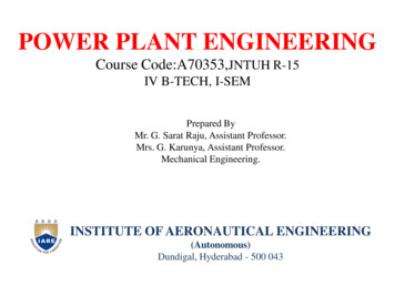
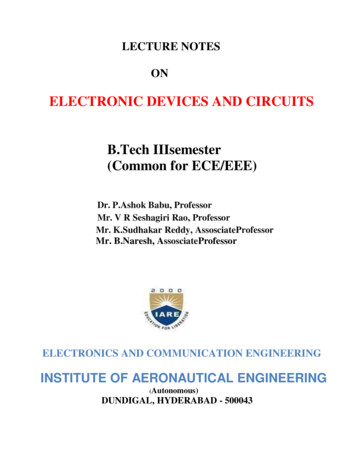
The definition of military aircraft mission payloads may cover a wide range of possibilitiesincluding personnel, troops, support equipment and supplies in transport aircraft and internallycarried stores, externally carried stores and sensor pods on combat aircraft.Specification Of Performance RequirementsMission Profile:Aircraft operations can be classified into civil operations, which are commercial flights transportingpassengers or cargo.Military operations which are concerned with defensive or offensive flight operations or theirassociated support operations.Figure:1.1 Measurement of air data; Air data computersA typical mission profile of a civil transport aircraft is shown in the above figure.The primary mission is to fly a payload from the departure point to the destination. This requires theaircraft to takeoff from the departure point, climb to the cruising height and cruise to the destination,where the aircraft descends and lands.If the aircraft be unable to land the destination when it arrives, it will have to divert to an alternateairfield and the flight plan will need to include provision for the diversion.IAREFlight MechanicsSource from Aircraft Performance by Martin E EshelbyPage 5
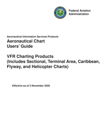
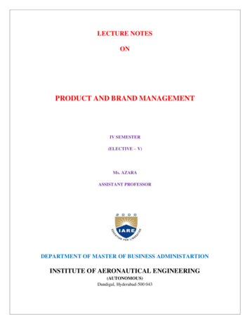
Figure:1.2 Military aircraft mission profilesOnce the mission profile and the payload of the aircraft have been specified the design process cancommence. From the performance standpoint the total design process extends from the initial projectdesign estimations right through to the delivery of the aircraft into service.In the final phase the aircraft is prepared for its operational role. The overall procedure can bedivided into 3 broad areas: Performance estimation Performance measurement Operational performancePerformance Estimation:Performance estimation involves the prediction of the capabilities of the aircraft from theconsiderations of its aerodynamic design, power plant and operating environment.It can be applied to1) The design of new type of aircraft2) Modification of existing aircraft type in respect to design changes affecting its aerodynamiccharacteristics or power plant3) To supplement or extend the full scale measured performance of an aircraft type forconditions outside those already establishedPerformance estimation process begins with the proposal of some performance target.IAREFlight MechanicsSource from Aircraft Performance by Martin E EshelbyPage 6
Initially the estimation will center on individual elements of the flight path. Performance estimation isusually based on the assumption of a simple atmosphere model, the international standard atmosphere(ISA). This is a linearized model of the temperature atmosphere which represents the mean globalatmosphere state with respect to seasonal changes and latitude and is used as the basis for aircraftdesign.Performance Measurement:A performance measurement is required for the three main purposes:1) To verify that aircraft achieves the estimated design performance targets.2) To demonstrate that the aircraft can satisfy the safety criteria set down in the worthinessrequirements.3) To provide validated performance data for the performance section of the flight manual.The performance of the aircraft is measured in development trials and compared with the estimatedperformance where there is difference in the characteristics of the aircraft and of the power plant canbe measured and compared with those used in the models.As the design of the aircraft is developed and the flight trials show that it is meeting its performancetargets, data was measured for submission to the airworthiness authority for the certification of theaircraft.As a part of the certification process validated performance data are required for the performancesection of the flight manual, known as the flight performance manual or the operating datamanual(ODM), which contains the information of the performance of the aircraft needed by theoperator for flight planning.Operational PerformanceThe basic requirements for the safe flight are that the space required for the aircraft to maneuvershould never exceed the space available, and that the aircraft carries sufficient fuel for the flightthese fundamental requirements form the basis of performance planning and fuel planning.IAREFlight MechanicsSource from Aircraft Performance by Martin E EshelbyPage 7
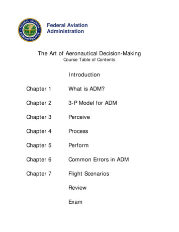
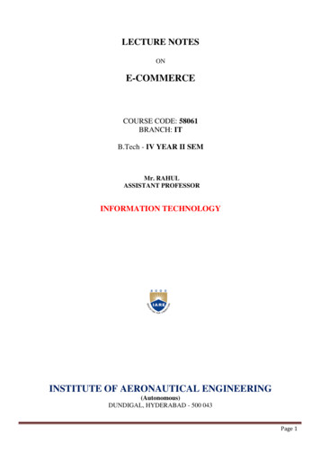
Performance planning: It is a part of the flight plan mode in advance of the flight ensures that at anypoint in the flight the aircraft has sufficient performance to be able to maneuver within the spaceavailable. The space required for any given maneuver is a function of the weight of the aircraft andthe space required increases as the weight increases.Fuel planning: It ensures that the aircraft carries sufficient fuel for the mission, taking into accountreserves for contingencies, diversions and safety. Since the fuel required for the mission will dependon the takeoff weight of the aircraft the fuel planning must follow the flight planning.The Atmosphere and Air data MeasurementThe state of the atmosphere defined by its temperature and pressure is fundamental to both thedesign and operation of the aircraft. The atmospheric air provides the lift force that propulsive forcethat is necessary to sustain flight. These forces depend on the properties of the atmosphere andaircraft.The Characteristics of the AtmosphereThe atmosphere consists of air which is a mixture of gases, mainly Nitrogen (78%), Oxygen (21%)with traces of argon (0.9%), carbon dioxide (0.03%) and other inert gases (0.07%) in minutequantities. There are quantities of dust particles, water vapor and moisture in variable amountswhich although they do not affect the gaseous properties of the air significantly.Figure:1.3Mean seasonal global temperature distribution.IAREFlight MechanicsSource from Aircraft Performance by Martin E EshelbyPage 8
The atmosphere air can be taken to behave as a neutral gas that obeys the equation of statep ρTRFigure:1.4 General global atmosphere pressure distributionVertical development of the atmosphereThe radiation that is absorbed by the atmosphere is not absorbed uniformly but selectively bydifferent layers giving rise to a complex temperature –height profile in the atmosphere.Figure:1.5 Vertical temperature structure of the atmosphereIAREFlight MechanicsSource from Aircraft Performance by Martin E EshelbyPage 9
At low levels the water vapor and carbon dioxide absorb the terrestrial radiation producing a warmair region near the ground extending upwards to about 11km, this layer is known as the troposphere.In the troposphere the temperature decreases with increasing height and the temperature-heightgradient which is negative here known as the temperature lapse rate, L. Above this region there islittle water vapor in the atmosphere and its absorptive is reduced, this layer is called the stratospherewhich extends upwards to some 50km. The ozone content of the atmosphere increases with heightup to about 80km and in the layer between 5km and 80 km. The absorptive particularly of the ultraviolet spectrum increases to form further warm air layer, this is the mesosphere. Above themesosphere is a layer of very low pressure the thermosphere, extending up to about 800km and thefinal layer, the exosphere forms the boundary with space.The standard atmosphere modelThe performance of the aircraft is depends on the state of the atmosphere in which it is flying. Thestate f the atmosphere, as defined by its pressure and temperature is viable, so that the actualperformance of the aircraft will depend on its geographical location and time. In the design of theaircraft assumptions of the state of the atmosphere will have to be made in order to predict itsperformance. A model of structure of the atmosphere is required.Figure:1.6 Measured temperatures – height profilesIAREFlight MechanicsSource from Aircraft Performance by Martin E EshelbyPage 10
The atmosphere model needs to represent an average atmosphere with respect to geographical andseasonal variations in pressure and temperature and to have a vertical structure which is similar tothat in the real atmosphere.An atmosphere model has been accepted by international agreement and is used as the basis for allperformance work, it is known as the International Standard Atmosphere.The reference datum values of the principal characteristics of the international standardatmosphere model are Reference pressure P 0 101325 N/m2Reference temperatureT0 288.15 KReference densityρ0 1.225 Kg/m3Figure:1.7 International standard atmosphere model; temperature – height profile.IAREFlight MechanicsSource from Aircraft Performance by Martin E EshelbyPage 11
The vertical structure of the atmosphere model is defined by the assumptions of a series of linearrelationships between temperature and height as shown in the above figure up to a height of 32kmwhich is the vertical extent of the ISA model used in connection with aircraft performance the modelconsists of three layers in each of which the temperature height profile is given byWhere the subscript I denotes the height of the layer boundary of the layer considered in kms. Thusat the datum level i 0 and the temperature lapse rate L i is the rate of change of temperature, weight,height in the layer above HiPressure heightFigure:1.8 Pressure heightIAREFlight MechanicsSource from Aircraft Performance by Martin E EshelbyPage 12
Figure:1.9 Design atmospheres. A) Pressure heights. B) Geo-potential heights.IAREFlight MechanicsSource from Aircraft Performance by Martin E EshelbyPage 13
The difference between pressure height and geo-potential height in an off standard atmosphere canbe determined in any atmosphereAnd in the standard atmosphere since H H pWhere Tstd is the standard atmosphere temperature at the pressure height HpThus a geo-potential height increment dH is related to a pressure height increment dH p by atemperature correction. This correction is used to obtain geo-potential height intervals frommeasured height intervals for the measurement of gradient of climb and other flight path relatedperformance characteristics.Relative properties of atmosphereThe atmospheric equation of state applies to all points in the atmosphere so that,And at the ISA datumThusThis can be writtenThe relative properties are a convenient means of expressing and manipulating the atmosphereproperties and avoiding the need to use the gas constant.IAREFlight MechanicsSource from Aircraft Performance by Martin E EshelbyPage 14
Figure:1.10International standard atmosphere; relative properties.Pressure height profiles;8000 ft δ 0.75 (maximum cabin pressure height forpassenger transport) 18000 ft δ 0.5 (short haul operations)38000 ft δ 0.2 (long range transport operations)53000 ft δ 0.1 (Concorde and some military operations)100000 ft δ 0.01 (TR1, SR71 surveillance aircraft, 80-90 000 ft)Density Altitude:It is sometimes more convenient to consider the state of the atmosphere in terms of its density ratherthan its pressure and temperature separately. In this case, the relationship between the density andheight in the standard atmosphere model is used as a datum.IAREFlight MechanicsSource from Aircraft Performance by Martin E EshelbyPage 15
Figure:1.11Density atmosphereThe concept of the density altitude can be illustrated by a simple example. If the observedtemperature at a pressure height 15000ft is -30*C then, from the pressure height relationship, therelative pressure at 15000ft isAnd the relative temperature isGiving the relative density to beNow from the properties of the standard atmosphere the pressure height at which a relative densityof 0.66878 occurs is 13120ft. thus the density altitude is 13120ft since the standard atmospheredensity at this height is equivalent to the actual density at a pressure height of 15000ft and atemperature of -30*C this is shown by point A in fig 1.10Measurement of air data:The essential requirements in the measurement of aircraft performance are first, the knowledge ofthe state of the atmosphere in which the aircraft is flying and secondly the relative motion betweenthe aircraft and the air mass. This information is collected by the air data system.IAREFlight MechanicsSource from Aircraft Performance by Martin E EshelbyPage 16
The air data system of an aircraft in fig 1.11 consists of a Pitot-static installation to sense the airflowpressures from which height, airspeed and Mach number are derived. An air thermometer fromwhich the air temperature can be determined and in some cases airflow direction detectors (ADD)which sense the local flow directions relative to the aircraft body axes are part of the system.Figure:1.12 Air data system of an aircraftBoth the air data computer and the mechanical instruments use the same basic calibration equationsto convert the measured data into a suitable form for operational use. The calibration equation willbe developed in the subsequent sections. The modules used in the display of air data are usually thefoot for measurement of height and the knot for airspeed since international regulation requiresprimary flight instruments to be calibrated in these modules.Measurement of height:In above section relationships were found the related pressure to geo-potential height in the standardatmosphere. By rearranging these equations height can be expressed in terms of pressure so that inthe troposphere in which L /0IAREFlight MechanicsSource from Aircraft Performance by Martin E EshelbyPage 17
And in the isothermal lower stratosphere in which L 0Although the standard atmosphere model uses a static pressure of 1013mb as its datum in practiceheight is measured with respect to other datum pressures, one of which is mean sea level. Fig 1.12shows the most common altimeter datum settingsFigure:1.13 Altimeter reference pressure settingsIn the measurement of height a number of corrections need to be taken into account before thepressure height and the quantities derived from pressure height can be determined. These can besummarized working back from the altimeter to the free stream flow.(a) Altimeter reading; Alt or HplThis is the reading of an individual instrument. Since the instrument is a mechanical device drivenby the static pressure, there will be errors due to mechanical tolerance.The instrument error correction can be evaluated by calibrating the individual instrument against anaccurate source of pressure and the correction applied to the altimeter reading to give indicatedaltitude.IAREFlight MechanicsSource from Aircraft Performance by Martin E EshelbyPage 18
(b) Indicated altitude;HpiThis is the altimeter reading corrected for instrument error. The indicated altitude will be measuredwith reference to the appropriate altimeter datum pressure setting.(c) Pressure altitude; HpThis is the indicated altitude measured with respect to the appropriate datum pressure settingcorrected for static pressure error. This is the error due to the location of the static pressure sourcewithin the disturbed pressure field caused by the presence of the aircraft.(d) Geo potential height interval; dHpThis is the pressure height interval, dHp measured by the altimeter and corrected for temperaturedifference from the ISA model atmosphere.(e) Static pressure p and relative pressureWhen the altimeter datum pressure is set to 1013mb the pressure heights can be converted intoatmospheric pressure or relative pressure either by reference to the atmosphere tables or from theISA pressure height relationship.Measurement of airflow characteristics:Airspeed is the relative velocity between the aircraft and the air mass in which it is flying. It is one ofthe most important parameters in aircraft performance since the aerodynamic forces acting on theaircraft, and upon which its performance is based are functions of airspeed.Since the total energy of the flow is constant the energy relationship neglecting the potential energyterm can be written in the formIntegrating above equation for adiabatic flow in whichIAREFlight MechanicsSource from Aircraft Performance by Martin E EshelbyPage 19
GivesRelating the flow pressure to the flow velocity ortrue airspeed V Alternatively from the equation ofstate 2.1And expressing the gas constant R in the formAbove equation can be written in the formThis relates the flow temperature to the true airspeed.Above two equations are alternative statements of the energy equation of the adiabatic flow of anideal gas and can be used in the measurement of the airflow characteristics.Measurement of airspeed:The airspeed can be measured by comparing the total and static pressures of the airflow relative to theaircraft. From above equation the energy at any two points in the flow are equal, thusIf point 1 refers to the undisturbed free stream conditions in which the pressure p 1 is the staticpressure p and V1is true airspeed of the flow V and point 2 refers to the stagnation conditions in thepitot tube in which the airflow velocity, V2is zero and the pressure p2 is the total or pitot pressure ppthen above equation becomes,IAREFlight MechanicsSource from Aircraft Performance by Martin E EshelbyPage 20
Now the speed of the sound a is given bySo that above equation reduces toComparing the total and static pressure provides the relationship between airspeed and the differentialpressure or impact pressure pdTHE FORCE SYSTEM OF THE AIRCRAFT AND THE EQUATIONS OF MOTIONThe equations of motion for performance:The equations of motion of the aircraft are statements of Newton‘s law, F ma, in each of threemutually perpendicular axes. The general force F is the sum of the components of a system of forcesacting on the aircraft, which results in the inertial force, ma. The system of forces acting on theaircraft can be categorized into four groups; the gravitational forces, Fg, the aerodynamic forces, Fa,and the propulsive forces, Fp, which result in the inertial forces, F1, so that the statement ofNewton‘s law becomes,There will also be a system of moments acting on the aircraft but, as these do not affect the flightpath directly, they do not need to be taken into account in the equations of motion for performance.Each group of forces acts in its own axis system and needs to be resolved into the velocity axissystem before the equations of motion for performance. Each group of forces acts in its own axissystem and needs to be resolved into the velocity axis system before the equations of motion can beIAREFlight MechanicsSource from Aircraft Performance by Martin E EshelbyPage 21
developed. The axis systems are described in full in Appendix A and the full equations of motion foraircraft performance are developed in Appendix B. Only a summary of the characteristics of theforces and the equations of motion will be considered here.In these equations of motion some simplifying assumptions have already been made, three includethe assumption that all engines are operating at equal gross thrust. For conventional aircraft,additional assumptions can be made to simplify the equations further, these are: That the rate of change of aircraft mass is negligible, m O. That the aircraft is in symmetric flights that O and Y O. That the gross thrust acts in aircraft body axes, 0. That the total net thrust Fn 0 and That the thrust component Tsin γ is small when compared with the lift force.When these assumptions are made, the equations of motion reduced to a simplified form that can beused for most performance analysis takes:The majority of performance analysis is based on the longitudinal equation of motion in which theterm, Fn – D, is known as the excess thrust and provides the increase in potential energy (climb), orthe increase in kinetic energy(acceleration).IAREFlight MechanicsSource from Aircraft Performance by Martin E EshelbyPage 22
The equations of motion stated above are written in terms of aircraft with thrust-producing engines.If the aircraft haspower-pr4oducing engines, which drive propellers to convert the power in to thrust,then the equations must be converted into their power form; this will be considered later in thesection on propulsive forces.The aircraft force system:In the development of the equation of motion, the forces acting on the aircraft are represented assimple force terms and appear as constants. However, the forces stated in equation and in theequations of motion are not simple forces but depend on the performance variables, aircraft weight,airspeed (or flight Mach number) and the state of the atmosphere. In particular, the aerodynamicforces and the propulsive forces are of great importance to the performance of the aircraft. Theircharacteristics will define, for example, the airspeeds for best climb rate and gradient and foroptimum range or endurance in the cruise part of the flight.Each group of forces can be considered in turn to determine how its characteristics very with theflight variables.The inertial forces, f1The inertial forces arise from the mass of the aircraft and its acceleration. The accelerations may belinear accelerations or result from the combination of the forward speed of the aircraft with its ratesof pitch and turn. The inertial forces act in the velocity axis system, which is discussed fully inAppendix B.The gravitational forces, fgThe gravitational force acts downwards in the Earth axis system and is the product of the aircraftmass, m, and the acceleration due to gravity, g. It may be referred to either as weight, W, or ass theproduct mg; each form of reference has its own applications within the theory and practice of aircraftperformance.The aerodynamic forces, faThe aerodynamic forces arise from the relative motion between the aircraft and the air mass in whichit is flying; they act in the wind axis system. It will be assumed that the reader is familiar with theIAREFlight MechanicsSource from Aircraft Performance by Martin E EshelbyPage 23
concepts of aerodynamics and this treatment will only consider the aerodynamic characteristics ofthe aircraft that are directly applicable to the study of performance.The dynamic pressure of the airflow, q, may be considered in terms of either airspeed or Machnumber,Whilst either form may be used when considering the non-dimensional aerodynamic forces, the forminvolving the Mach number is particularly useful when considering operational performance. If theairspeed is considered in terms of the flight Mach number, then the temperature of the atmosphere isimplicit in the statement of the Mach number and the atmosphere pressure can be consideredindependently. Since altitude is related uniquely to the static pressure of the atmosphere, the altitudebecomes a basic variable of the aerodynamic forces. Therefore, the forces need to be consideredonly in terms of their variation with aircraft weight, flight Mach number and altitude a rather than interms of aircraft weight, airspeed, altitude and temperature.The aerodynamic forces that concern performance are the lift, L, the drag, D, and the side force, Y.In the case of an aircraft, the speed of flight is relatively high and the non-dimensional flow variablesthat characterize the flow are,(i) The Reynoldsnumber,Typically the flight value of Re is large, 10 to 10, and the flow can be treated as continue flow. If theaerody
IARE Flight Mechanics Source from Aircraft Performance by Martin E Eshelby Page 8 Performance planning: It is a part of the flight plan mode in advance of the flight ensures that at any point in the flight the aircraft has sufficient perfo