Transcription
S.P. Burkova, G.F. Vinokurova, R.G. DolotovaDESCRIPTIVE GEOMETRY1
«NATIONAL RESEARCH TOMSK POLYTECHNIC UNIVERSITY»DESCRIPTIVE GEOMETRYExercise-book of a practical courseTOMSK 20132
УДК 514.18(075.8)ББК 22.151.3я73Б914Б914Descriptive geometry: Exercise-book S.P. Burkova, G.F. Vinokurova,R.G. Dolotova; Tomsk: TPU Press. 2013. – 66 с.The working book on descriptive geometry and the engineering drawingis developed for first-year students. The writing-book is used for work onlecture employment under the direction of the teacher.This work book is intended for distance leaning Engineering Graphicsfor the Certificate of Higher Technical Education.УДК 514.18(075.8)ББК 22.151.3я73Reviewed by:Prof. Dr. B.A. LjukshinProf. A.L. StukanovProf. N.A.AntipinaT.I. Butakova NR TPU, 2013 S.P. Burkova, G.F. Vinokurova, R.G. Dolotova2013 Registration. Tomsk: TPU Press, 20133
CONTENTSCONTENTS .4PREFACE .5CHAPTER 1. THE PRINCIPAL RULES OF A DRAWING PRESENTATION .61.1 Formats and Title Blocks .61.2 Scales .81.3 Lines .81.4 Lettering .10CHAPTER 2. THE METHOD OF ORTHOGONAL PROJECTIONS.152.1 Drawing of Point .152.2 Drawing of a Line-Segment. Straight Lines of a Particular Position .172.3 Mutual Positions of a Point and a Line.192.4 Traces of a Line .192.5 The Relative Positions of Straight Lines .202.6 Method of Replacing Planes of Projection.23CHAPTER 3. REPRESENTATION OF A PLANE IN A DRAWING .253.1 Ways of Specifying a Plane .253.2 The Point and the Line in the Plane .273.3 The Principal Lines of the Plane .283.4 The line intersects the plane .303.5 Mutual Positions of the Planes .313.6 Method of Replacing Planes of Projection.33CHAPTER 4. SURFACES .364.1 Ruled surfaces .364.2 Rotation Surfaces .444.3 Mutual Intersection of Surfaces .50CHAPTER 5. AXONOMETRIC PROJECTIONS .55Work 1 Transformation of the drawing .58Work of 2 Surfaces .60Work 3 Crossing of surfaces .61QUESTIONS .624
PREFACEThis writing-book is intended for studying the course “EngineeringGraphics” by students of technical specializations of TPU who go throughthe Bachelor Degree Program. The working writing-book contains drawingsof tasks, text conditions of problems, control questions on the basic sectionsof a course; in it the place for the geometrical constructions which are carriedout by students in audience is provided. The following designations areaccepted in the present book:1. Points of space are usually denoted by Latin capital letters (A,B,C) orfigures (1,2,3);2. Sequence of points (and other elements) - by interlinear indexes(A1,A2,A3,B1,B2,B3,);3. Lines in space - by the points specifying the given line (AB, CD,);4. Angles - by Greek small letters ( , , )5. Planes - by Latin capital letters (P, R, Q)6. Surfaces - by Greek capital letters ( , , ,)7. Projection centre – S8. Projection planes: horizontal – H; frontal – V; profile – W9. Coordinate axes system - xyzO, where: abscissa axis – x; axis of ordinates – y; applicate axis – z; origin of coordinates – O (capital letter); new projection axes obtained at planes replacing – x1,y2;10. Point projections – by the corresponding lower-case letters (a,b): for horizontal projection plane – a; for frontal projection plane – a ; for profile projection plane – a ;11.Line projections - by projection of the points specifying the line – ab, a b ,a b .12. Coincidence, identity – ;13. Coincidence, equality – ;14. Parallelism – ;15. Perpendicularity – ;16. Representation – ;17. Belonging of an element (a point) to a set (line, plane, etc.) – ;18. Belonging of a subset (a line) to a set (plane, surface) – ;19. Intersection of sets – .20.Crossing – .5
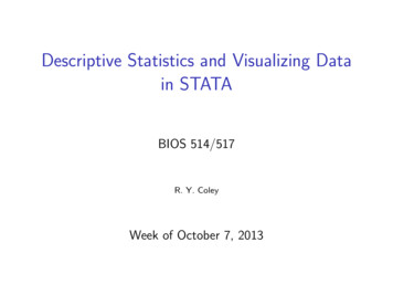
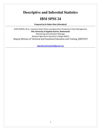
CHAPTER 1. THE PRINCIPAL RULES OF A DRAWING PRESENTATIONThe unified rules on presentation of drawings and other technical papersare regulated by Unified System of Engineering Papers (USEP).Engineering papers are the graphical and text documents specifying(separately or as a set) the construction of a product, and including allnecessary data for its manufacture, control, operation and repair.1.1 FORMATS AND TITLE BLOCKSFormat (from Latin “forma” - looks, appearance) - the size of drawingsheets and other engineering papers. The regulations establish the followingformats and their designations:Format designationA0A1A2A3A4Dimensions of a841x1189594x 841 420x 594 297x 420 210x 297format, mmThe format of paper sheets corresponds to the dimensions of thedrawing external frame passed with a thin line (the line of clipping a drawingafter its completion). The frame of drawing is produced with the base-line.The distance between the edge of paper and the frame is 5 mm and morespace is on the left side (20 mm). A specimen lay out (with title blocks, 185 x55, and an additional box, 70 x 14) is shown in Fig. 1.Sizes A0 A3Size A4Fig. 1The title blocks are drawn in base and thin lines (Fig. 2). Theinformation in the title blocks is arranged in the following way:Box 1 – Name of item (of your task) Lettering 7,6
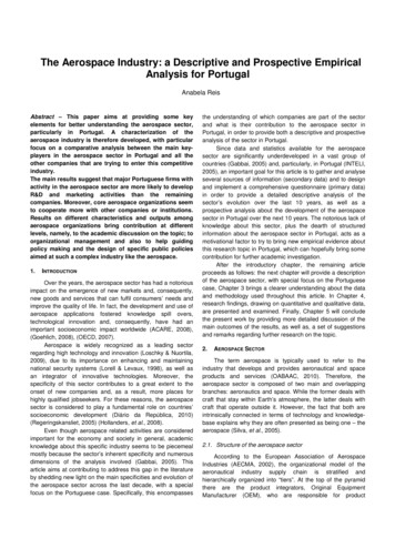
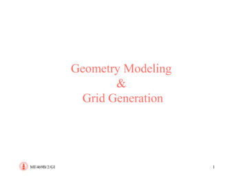
Box 2 – Drawing Designation (Lettering 7)DGG I. XXXXXX. 001a bcda – Department of Descriptive Geometry and Graphics;b – Test number;c – Classification characteristics of the item (for a detail or anassembly unit drawing) or XXXXXX (for other drawings);d – The last figure of the student’s card number;Box 3 – Material of the item;Box 4 – “T” (training drawing);Box 6 – Scale (is not denoted on a sketch)Fig. 2 Title Blocks (Form 1)Box 7 – Sheet number (if the task consists of one sheet, the box is notfilled in)Box 8 – Total number of sheets in the test (is filled in only on the firstsheet of the test)Box 9 – TPU (Tomsk Polytechnic University), CDL (Center ofDistance Learning), Group numberBox 10 – Student’s NameBox 12 – Student’s SignatureBox 13 – DateOther boxes are not filled in for training drawings.7
1.2 SCALESScale is a ratio of a representation’s dimensions to the naturaldimensions of a product.According to the drawing’s complexity and the dimensions of the itemsbeing represented, select the scales from the following table:ReductionscalesNominal scaleIncrease scales1:2; 1:2.5; 1:4; 1:5; 1:10; 1:15; 1:20; 1:25; 1:40; 1:50; 1:75;1:100, etc.1:12:1; 2.5:1; 4:1; 5:1; 10:1; 20:1; 40:1; 50:1; 100:1; etc.Choose a scale to make working with a drawing easier.The Scale is inserted in the box “Scale” of the title blocks. Whendimensioning a drawing, the scale different from that printed in the titleblocks, is placed just above the representation near the representation sign.Example: for extension elements, auxiliary and detail views - A(2:1)for sectional views and sections - A-A(2:1)1.3 LINESThe Regulations establish design and principle applications of lines ondrawings for all production and construction industries.Thickness s of a continuous base-line must be 0.5 - 1.4 mm, dependingon the size and complexity of the representation and on the drawing size(format). The lines of one drawing must be of equal thickness on allelevations drawn to one scale. You are recommended to draw continuousbase-lines 0.8 - 1 mm thick.The standard establishes the minimal thickness of lines and the minimaldistance between adjacent lines depending on a drawing size; it alsospecifies the outlining of representations: the length of dashes of dashed and dash-and-dot lines depends on thedimensions of representations; dashes should be approximately equal in length; spaces between dashes of each line must be approximately equal; dash-and-dot lines must intersect and end in dashes; dash-and-dot lines applied as centre lines should be replaced bycontinuous thin lines, if a circle diameter or dimensions of othergeometric figures on representation is less than 12 mm; for complex sectional views and sections it is permitted to connect theends of a broken line by a thin chain line.8
The Lines and Their ApplicationsItemOutline1. Continuousthickbaseline2. ContinuousthinThicknesssFroms/3to s/23. Continuousirregular(wavy)4.Shortdashes(dashed line)5.Chain(dash-and-dotline)Froms/3 to s/2Froms/3 to s/2Froms/3 to s/26. Chain thickFroms/2 to 2/3s7. Broken8. Continuouspolygonalthin9.Doubledotted chainFroms to 1.5sFroms/3 to s/2Froms/3 to s/29Principal ApplicationsVisible outlines; visibletransition lines; outline of section(removed and detail)Outlinesofcovering(revolved) section; dimension andextension lines and their shelves;hatching; outlines of adjacentparts; limit lines;imaginary,fictitious lines; traces of planesBreak lines; separating linesbetween a view and a sectionalviewHidden outlines, invisibletransition linesAxis and centre lines;section lines being symmetry axesfor removed and covering sectionsIndication of surfaces whichhave to meet special requirements;lines of elements located in frontof a cutting plane (“coveringprojection”)Section linesLong lines of a breakBendlinesofdevelopments; lines of parts ofproducts in utmost or intermediatepositions; lines representing adevelopment coincided with aview
1.4 LETTERINGAll notes on drawings and other technical papers are completed by thedrawing lettering. The lettering for technical papers of all production andconstruction fields is regulated by a standard.The principal lettering parameters:lettering size h – height of capital letters in mm, measured along a lineperpendicular to the basis of line;height of small letters c (without branches - k);width of a letter g – maximal width of a letter;thickness of a lettering line d depends on type and height of lettering.There are the following lettering types:type A without sloping (d 1/14h); type A with sloping of about 75 (d 1/14h); type A with sloping of about 75 (d 1/10h);type B without sloping (d 1/10h);type B with sloping of about 75 (d 1/10h), with the parameters shownin the table.The following lettering sizes are specified by the standard:(1.8); 2.5; 3.5; 5; 7; 10; 14; 20; 28; 40Lettering of Type BParameterLettering sizeHeightofcapital lettersDistancebetween lettersMinimal paceof linesMinimal spacebetween wordsThickness oflettering linesDes-n Relative )hdd(1/10)h12.5Dimensions, .08.5121761.52.13.04.26.0d0.30.40.50.71.0Notes:1. Distance a between the letters the neighbouring lines of which are notparallel to each other (e.g. TA, AT), may be reduced by a half, i.e. by thethickness d of the lettering lines.2. Minimal distance e between the words, separated by punctuationmarks, is the distance between a punctuation mark and a word following it.10
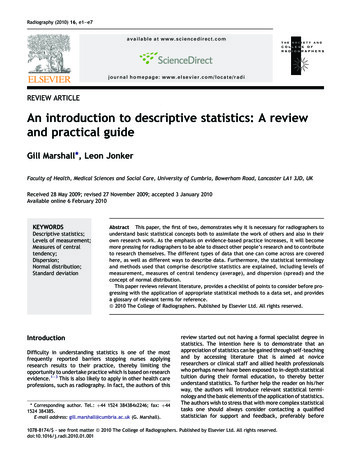
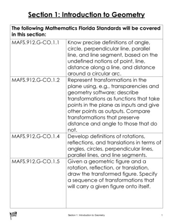
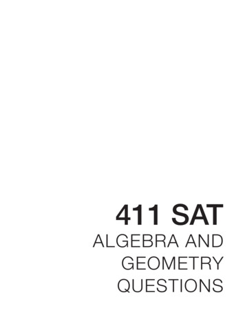
Width of Letters and FiguresWidthsmall lettersofWidthcapital lettersofWidth ofWidth Width ofsmall lettersofcapitalfigureslettersand Letters and Figures142,3,5,6,7,8,9,0 p,q,s,u,v,x,y,zm,wRelative 5d6d6d7d9dd2d3d4d5d5d7dLettering dimensions, mm2.5 3.5 5.0 7.0 100.8 1.1 1.5 2.1 31.1 1.6 2.3 3.2 4.51.3 1.8 2.5 3.5 52.5 3.5 57101.3 1.8 2.5 3.5 51.5 2.1 34.2 61.5 2.1 34.2 61.8 2.5 3.5 4.9 722.8 45.6 811.4 22.8 41.1 1.6 2.3 3.2 4.51.3 1.8 2.5 3.5 51.3 1.8 2.5 3.5 51.5 2.1 34.2 61.8 2.5 3.5 4.9 70.3 0.4 0.5 0.7 1.011.4 22.8 41.3 1.8 2.5 3.5 51.5 2.1 34.2 61.5 2.1 34.2 61.8 2.5 3.5 4.9 72.2 3.1 4.5 6.3 90.3 0.4 0.5 0.7 1.00.5 0.7 1.0 1.4 2.00.8 1.1 1.5 2.1 3.011.4 22.8 41.3 1.8 2.5 3.5 51.3 1.8 2.5 3.5 51.8 2.5 3.5 4.9 7Standard drawing lettering consists of the Russian, Latin and Greekalphabets, and the Arabian and Roman figures and symbols. A specimen ofthe Russian and Latin lettering is presented in Fig.3, 4.11
Fig. 3Fig. 412
Font 7 to w
The working book on descriptive geometry and the engineering drawing is developed for first-year students. The writing-book is used for work on lecture employment under the direction of the teacher. This work book is intended for distance leaning Engineering Graphics for the Certificate of Higher Technical Education. УДК 514.18(075.8) К 22.151.3я73 Reviewed by: Prof. Dr. B.A. Ljukshin .