Transcription
WIRE ROPEUSER MANUALushamartin.com
USHA MARTIN GROUPUsha Martin is one of the largest manufacturers of high quality wireropes in the world.For more than 50 years, the group has been dedicated to excellenceand has implemented stringent process controls at each step of themanufacturing process.The Usha Martin Group, with it’s own coal and iron ore mines, 150 MW power plant and over 1million tons of speciality steel manufacturing capacity, is a truly vertically integrated business.It has a global base of steel wire rope manufacturing facilities located in India, the UK, Thailand andDubai with service centres spread over all of the key markets in Europe, Asia, Americas and Africa.In this world without boundaries, Usha Martin is truly committed to preserve this legacy of quality allover the world and continues to harness it’s global presence to deliver the best possible solutions forit’s customers.
List of topicsPreface about rope use .2Rope diameter and measurement .3Rope lay measurement and selection.4Strength & breaking force.6Material & surface finish.7Benefits of compacted strands.8Fleet angle and plastic impregnated core ropes.9Rope behaviour under load.10Rotational characteristics.11Block stability and use of swivel .12Wire rope lubrication.14Reel receipt and storage.16Serving and cutting.18Rope pay out.19Rope terminations.20Socketing operation.22Rope installation and training.24Lifting operations.26Rope winding over sheaves.28Contact pressure between rope and sheaves.30Rope relubrication.32Bending fatigue.33Factors affecting bending fatigue.34Guidelines for rope inspection.36Inspection of grooves and sheaves.38Typical rope damages and recommended actions.39Discard criteria for visible broken wires.40Discard criteria for diameter decrease, deformation and corrosion. . .42Health and safety information.44Appendix A Quick calculator.46Appendix B Definitions.47Appendix C Reference documents.51Appendix D Examples of strands and ropes constructions.5201This document is property of Usha Martin Italia. Reproduction is not allowed unless specifically agreed.
PREFACE ABOUTROPE USEA wire rope can be simply considered as anRope integrity management should always beassembly of several strands laid helically inoperated by properly trained personnel, whodifferent possible arrangements in order toshould always refer to general regulations,bear axial loads.specific customer standards, local legislationTo be fit for purpose, it must also ensure otherand internal guidance.features, like resistance to side loads, flexibility,The content of this document is a brief abstracthandling and stability.of rope characteristics and recommendationsThis definition, however, does not coverfor rope use and it is not intended to becompletely the implications of correct ropeall-inclusive; specific matters can be followeddesign, manufacturing, use and inspection,with special care to customer needs by ouras the real mandatory requirement must be,technical departments.in any case, safety compliance, which allowsadequate working conditions for men andenvironment.To ensure high quality standards, our Companyhas settled up a complete process, which includescustom design software, state of the artmanufacturing equipment and skilled personnelwith proven expertise.This document is property of Usha Martin Italia. Reproduction is not allowed unless specifically agreed.
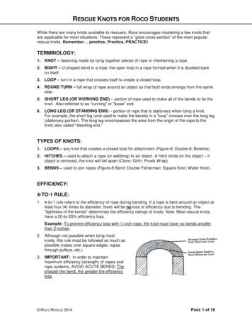
ROPE DIAMETER ANDMEASUREMENTEach rope is first of all characterized by theDiameter must be measured and recordednominal diameter and oversize, which have toimmediately after rope receipt, as this valuebe selected depending on system configurationhas to be used as a baseline for followingand reference regulations.inspections.According to EN12385-1, ISO and API standard,It has always to be considered that the actualdiameter measurement has to be taken on adiameter of the rope changes during use duestraight portion of the rope, either under noto initial stabilization, to the effect of workingtension or a tension not exceeding 5% of thetension and to wear generated by the passageminimum breaking force, at two positions spacedover the reeving system.at least one metre apart. At each position twoPermanent diameter reduction after first pullmeasurements, at right angles, of thecan vary from 0.5% to 3% depending on ropecircumscribed circle diameter shall be taken.and core construction.The most suitable measuring equipment is plateDiameter measurement is an essential tool whichgauge, capable to cover at least two strandscan give an immediate and simple evaluation of(see Figure 1).the overall condition of the rope.For example, a localized diameter variation canindicate undesired phenomena like geometricaldeformation, core distortion or presence ofheavy corrosion, while a distributed diameterreduction can be associated to wear due tointensive use. Ovalization is also a marker ofpossible rope issues which have to be properlyaddressed.Figure 1 Diameter measurementFigure 2 Sunken strand and associated diameter reductionFigure 3 Core distortion and associated diameter increase03This document is property of Usha Martin Italia. Reproduction is not allowed unless specifically agreed.
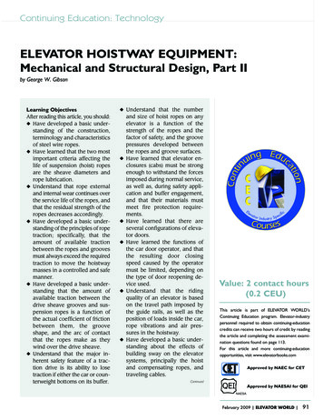
ROPE LAY MEASUREMENTAND SELECTIONLay length represents one of the keyThe choice of a Lang or regular lay rope has tocharacteristics of the rope and affects itsbe based on rope use and desired performance.elasticity and performance under load.Lang lay ropes (i.e. ropes having same directionIt has to be periodically measured, as possibleas the outer strands) give better stabilityvariations can indicate rope issues, like forcedto side wear (phenomenon also known asrotation during installation, or unlay due to“crushing”) as the contacts between the wiresexcessive lifting height, or misalignment of theof adjacent rope wraps are smoother. They arereeving components.particularly indicated up to 40 mm size ropesused on deck cranes or small winches.Regular lay ropes (i.e. ropes having oppositedirection in respect of the outer strands) ensureimproved rotation stability and are thereforeFigure 4 Lay length measurement for a six strand roperecommended for relevant lifting height orhigh capacity cranes.Figure 5 Lang lay (first figure)and regular lay (second figure)This document is property of Usha Martin Italia. Reproduction is not allowed unless specifically agreed.
The natural tendency of the rope to twist mustIn case of grooved drums, an adequate numberbe in accordance with the direction of drumof safety wraps should remain in place to avoidwinding to get a tight contact between adjacentrope slipping, while in case of plain drums thewraps, especially on the first layer.whole first layer should never be used, as itIn case of plain drum, right hand or left handworks as a bedding for the following layers.lay direction must be selected in order toPainting the first layer or the safety wraps ismatch the drum’s type and direction, as showna good practice to clearly detect the use of ain the figure.forbidden portion of rope.These indications are not strictly required forgrooved drums, as in this case the rope is alreadyguided by the grooves themselves.In case of grooved multilayers drums, laydirection can be selected to facilitate the firstlayer spooling or optimized considering therope layer that will be more frequently usedduring operations.Figure 6 Selection of lay direction05This document is property of Usha Martin Italia. Reproduction is not allowed unless specifically agreed.
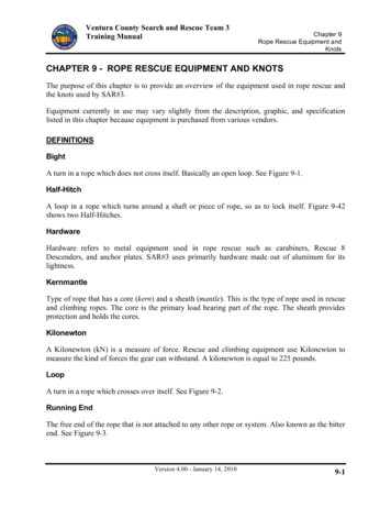
STRENGTH & BREAKINGFORCEA fundamental requirement for wire ropes isGood quality ropes must be composed ofthe achievement of the minimum breakingductile wires, which will break graduallyforce that complies with the crane or winchfollowing remarkable plastic deformation.safe working load.These gradual breaks will be clearly noticeableRope breaking force can be seen as a functionby a competent person with responsibility forof metallic area, strength and spinning factor.rope integrity management.These elements must be carefully combined toRopes that rely solely on the use of extremelyconfer reliable mechanical properties.high strength wires for their breaking force canMetallic area depends on geometricalhave severe implications in terms of safety,construction, diameter oversize andas the wires will have the tendency to breakcompacting level, strength is dependent onsuddenly without giving proper notice ofthe characteristics of the individual wires, andarising problems.spinning factor is dependent on manufacturingThe graph below compares the behaviour ofskill, geometrical construction and compactingwires with different strengths: the first figurelevel.represents a brittle trend typical of highHowever, it must be emphasised that a highstrength steel (over 2160 N/mm²). The secondbreaking force in itself is not sufficient tofigure represents the typical trend of lowerensure safe working conditions.strength steel (1770 and 1960 N/mm²).These can be achieved if it is possible toIt is therefore essential to adopt the minimumdetect within an acceptable time scale thatpossible strength level and to achieve thethe rope is approaching the end of its usefuldesired breaking force by a combination oflife or that the prescribed payload has beenhigh compacting level, finely tuned geometricalexceeded.construction and manufacturing reliability.Figure 7 Stress - strain curvesThis document is property of Usha Martin Italia. Reproduction is not allowed unless specifically agreed.
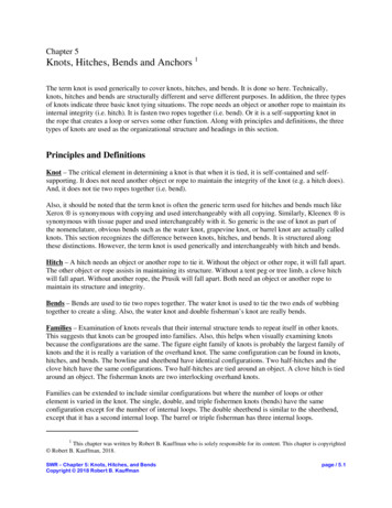
MATERIAL & SURFACEFINISHCorrect selection of raw material is essentialin order to get the required breaking force andmechanical characteristics.Our wire ropes are manufactured using a highcarbon content, patented rod, which allows toachieve high rope grades without the adoptionof extreme wire strength.The rod is subjected to a drawing process,which consists of a number of passages througha series of tungsten carbide dies with a gradualFigure 8 Galvanized wirediameter reduction. During this process, themetallurgical structure of the rod changesZinc is applied by a hot dip process in orderfrom a very thin perlite pattern to well alignedto avoid hydrogen embrittlement typical offibres with high tenacity and strength.electrochemical plating. Hot dip galvanizingThe combination of carbon content andcreates a tight connection between zinc andamount of drawing is determined depending onsteel, virtually alloying them in one unique entity.the specific application of the wire rope andFor severe environmental conditions, improvedthe required mechanical characteristics.surface finishing based on zinc aluminiumSteel has to be protected against corrosionalloys can also be adopted.and consequently bright ropes, which are stillIt must be emphasised that surface finishingpopular for some applications, have a veryhas to be adopted in conjunction with adequatelimited use in oil and gas applications, whilelubrication and maintenance levels in order tozinc coating is highly recommended for thepreserve wire rope performance.marine environment.The quantity of zinc which has to be appliedto wires is regulated by EN10264-2 – Steelwire and wire products – Non ferrous metalliccoatings on steel wire – Zinc or zinc alloy coatings.For rope used within the oil and gas industry,the typical zinc thickness is approximately 20to 25 microns, which complies with class B.07This document is property of Usha Martin Italia. Reproduction is not allowed unless specifically agreed.
BENEFITS OF COMPACTEDSTRANDSRopes for heavy lifting and special applicationsrequire a high load efficiency and breakingload, which cannot be achieved using traditionalround strands. For this reason, these ropesare typically composed of compactedstrands, where the level of compaction can beFigure 9 Compacting processthrough rollers or diedesigned and modulated depending on specificrequirements.Compacted strands are created by passingthrough a die or a series of rollers situated justafter the closing point of the stranding machinesas shown in the figures.Figure 10 Round strand, light andhigh compacting levelThe main benefit achieved by use of compacted strands adoption is the increase of metallic area inrespect to round strands, which leads to higher breaking force. Moreover, compacted strands allowto achieve higher cooperation level of the individual wires, homogeneous and stable strand diameter,resistance to side pressure, wear and abrasion.Finally, the smoother contact surface between the strands and rounder profile gives better spoolingperformance and resistance to crushing.Figure 12 Contact surfacesfor a non compacted and a compacted ropeFigure 11 Round strandversus compacted strandThis document is property of Usha Martin Italia. Reproduction is not allowed unless specifically agreed.
FLEET ANGLE AND PLASTICIMPREGNATED CORE ROPESRope routing must be carefully considered toFleet angle should never exceed 2 , it can beprevent early damage: one of the most criticalincreased up to 4 with the adoption of plasticfactors is the presence of deflection (i.e. fleet)impregnated core ropes.angles between two sheaves or from the drumIn this type of ropes, plastic is applied to the coreto the spooler.after its closing and is lightly heated and softenedbefore final closing in order to create a connectionbetween outer strands and core strands.The plastic layer must not work as a cushion(see left sketch), but must allow steel oversteel contact between the core and theFigure 13 Fleet angle during spooling and rope rollingouter strands (see right sketch). This ensureslong-lasting radial stiffness and rope stability.When fleet exists, the rope is induced to rolland slide into the groove, causing shorteningand increasing of the lay length and possiblepermanent distortion of the rope structure,such as birdcage or core protrusion.Figure 16 Cushion layer versusplastic impregnated coreFigure 14 Birdcage deformationFigure 15 Core protrusion09This document is property of Usha Martin Italia. Reproduction is not allowed unless specifically agreed.
ROPE BEHAVIOURUNDER LOADWhen a rope is subjected to axial loads, theelasticity of the material causes elongationand consequential diameter reduction.The first graph shows the relationship betweenstress (ratio between load and metallic area)and strain (ratio between elongation and initialsample length). The slope of the curve is Youngmodulus “E”, which multiplied by the metallicsection “A” gives the axial stiffness “EA”.In the first phase of its use (up to point 1),rope shows a certain permanent stretch due toFigure 17 Stress - strain curve for a wireropethe stabilization of the individual wires.After this step, the trend is basically linear upto the achievement of yield point (points 3 and4), from which permanent plastic deformationtakes place, until the load reaches the actualrope breaking force.A typical example of relationship between ropeoversize (ratio between actual and nominaldiameter) is indicated in the second graph.After training, every rope shows a permanentdiameter reduction due to the stabilizationof its structure. The initial diameter and theFigure 18 Rope oversize versus loadconsequent reduction must be such to allowsmooth installation on the drum and goodspooling.This document is property of Usha Martin Italia. Reproduction is not allowed unless specifically agreed.
ROTATIONALCHARACTERISTICSBeing composed by helically laid elements,Each rope is characterized by torque factor,each rope has the natural tendency to twistwhich is used in the calculations when bothwhen subjected to axial loads.ends of the rope are fixed, and rotation factorThe level of twist is dependant on the(expressed in degrees/lay), which is usedgeometrical arrangement and can be reducedwhen one end is free to rotate.by compensating the core tendency to rotateBoth torque factor and rotation factorin one direction with an opposite tendency ofstrongly decrease after rope stabilization andthe outer layer, as typically applied to spinare negligible if the rope is always used atresistant and non rotating ropes.same working load and lifting height.Ropes are conventionally classified based onthe number of turns that a portion with lengthof 1000 times the nominal rope diameter wouldmake when pulled at 20% MBF (see figure):1. Non rotating: less than 1 turn2. Low rotation: from 1 to 4 turns3. Spin resistant: from 4 to 10 turns4. Not non rotating: more than 10 turnsFigure 20 Torque factor for non rotatingand six strand ropesFigure 19 Rope classificationbased on number of turnsFigure 21 Rotation for different ropeconstructions11This document is property of Usha Martin Italia. Reproduction is not allowed unless specifically agreed.
BLOCK STABILITY AND USEOF SWIVELIn case of single fall lifting a non rotating ropeIn case of special block arrangement, pleaseis typically recommended, while in case ofcontact us for a custom evaluation.multi-part reeving arrangement, rope typeWhen operating a non rotating rope in singlehas to be selected depending on height of lift,fall mode, a swivel can be used to relieve theblock configuration and loading.rope of any induced rotation resulting fromA wrong rope selection or improper installationangular deflections at a sheave or drum.and training can cause cabling phenomenon,Swivels must not be used with not non rotatingwhich can lead to permanent rope deformation,ropes, like 6 strand, as it would cause ropelike waviness, and severe operations issues.unlay, severe reduction of its breaking forceThe maximum lifting height for a given ropeand secondary fatigue of the steel core, nottorque factor “t” can be briefly calculateddetectable during inspections.using the approximate formulas shown in thesketch (all dimensions are in m).Figure 22 Multiple fall liftingThis document is property of Usha Martin Italia. Reproduction is not allowed unless specifically agreed.
Figure 23 Calculation of maximum lifting heightFigure 24 Rope wavinessFigure 25 Example of swivel13This document is property of Usha Martin Italia. Reproduction is not allowed unless specifically agreed.
WIRE ROPE LUBRICATIONProper lubrication is essential to maintain ropeLubricant can be applied during differentperformance in use, protect it against corrosionmanufacturing phases: stranding, core closingand preserve its service life.and final closing.Good quality lubricants are characterized byWhen applied during stranding, the lubricanthigh adherence to steel in order to withstandis firmly engaged within the rope structure andpassage over the reeving system, light colouringreduces friction between the wires. If appliedwhich will not obstruct the detection of possibleduring core closing it creates a barrier againstrope damage and high compatibility with otherexternal elements penetration and if appliedproducts, which is particularly important forduring final closing it further increases protectionvessels operating globally.against corrosion.Drop point has to be high enough to tolerateThe quantity of lubricant applied during roperope storage and operation in warm environment,manufacture has to be carefully evaluated onbut with a safety borderline that is sufficientthe basis of rope use and working environment.to detect rope overheating during the use ofspecial devices such as heave compensators.Since steel can suffer permanent deteriorationif subjected to high temperatures for extendedperiods, a good temperature limitation andconsequent drop point is approximately 80 C.Figure 26 Example of rope with very low outer lubricationThis document is property of Usha Martin Italia. Reproduction is not allowed unless specifically agreed.
If insufficient lubricant is applied, the ropeThe most typical levels of lubrication arewill not be adequately protected, however anshown in the following figure:excess of lubricant may be squeezed out of the first image refers to very small sizethe rope during installation and use, therebyropes, with lubrication applied only duringcreating environmental and safety issues.strandingThis has to be carefully considered in case of the second figure refers to ropes forboom hoist ropes operating on offshore vessels,industrial lifting, with lubrication appliedwhich run over reeving systems composed of aduring stranding and core closinghigh number of sheaves. the third figure refers to ropes for marineBefore rope installation and during rope use,environment applications, with lubricationthe lubrication level must be periodicallyalso applied during final closing operations.inspected to detect any overall or localisedThis is the most frequent option for oil andfaults and, where required, relubrication can begas applicationsperformed by using appropriate pressure devices. the fourth image shows a very highFor ropes operating subsea, lubricant shouldamount of lubricant, required for ropesbe applied during deployment in order to filloperating subsea or dealing with verythe strands gaps and prevent water penetrationsevere environmental conditionsand trapping.Figure 27 Typical lubrication levels15This document is property of Usha Martin Italia. Reproduction is not allowed unless specifically agreed.
REEL RECEIPT ANDSTORAGEAfter receipt, the rope should be immediatelySlings must have an adequate length to avoidchecked to verify its identity and conditionflange ends overstress during reel lifting.and should not be used without the possessionThe rope should be checked to verify that it isof adequate documentation and certificates.not damaged when unloaded and transported toThe Certificate of Conformity by the manufacturerstorage site and should not come into contactshould be stored in a safe designated place inwith parts of the lifting devices, like hooks andorder to quickly identify the rope and carryforks.out periodic inspections.Some recommendations for rope handling areDuring loading, transferring and unloadingindicated on specific labels applied on the reels.operations, rope reels or coils should beproperly handled using slings or lifting beams.Figure 28 Rope handling recommendationsThis document is property of Usha Martin Italia. Reproduction is not allowed unless specifically agreed.
Storage conditions are essential to preventThe rope should not be stored in places whichrope damage: it should be avoided to keep thecould be affected by chemical agents, corrosiverope in very warm or humid environment, asmatters or accidental damages and, if storedthis could break down the effectiveness of nativeoutside, the reel should be positioned in orderlubrication and accelerate the deteriorationto avoid direct contact with the ground andprocess. If lubricant has the tendency to draincovered with waterproof material.due to high temperature, the reel should beThe rope marking should be clearly detectableperiodically rotated to maintain a homogeneousand readable in order to safely and quicklydistribution.identify the reel.Figure 29 Reel handling17This document is property of Usha Martin Italia. Reproduction is not allowed unless specifically agreed.
SERVING AND CUTTINGDuring manufacturing process, the strands canWire diameter shall be such to firmly hold thebe preformed in order to get a helical profilestrands and, particularly in case of large sizejust before closing and improve rope stabilityropes, seven wires strands can be used as anand handling. Similar purpose can be achievedalternative to single wires.through postforming, which consists of theBefore cutting the rope, a clear mark shouldpassage of the rope through a series of rollers.be applied on the cut area and servings shouldWith the exception of very specific applications,be applied at each side of the mark.preforming and postforming level must be suchDepending on its size, the wire rope can beto stabilize the rope without reaching extremefused and tapered or cut using high speed abrasivelevels, as this would make the rope very faintdisc cutters, percussive or shearing methods,during use.paying particular attention not to disturb theTherefore, unless the rope has been subjectedposition of wires and strands below the serving.to complete preforming, it will have theRope core can be cut with no major issues intendency to unlay when cut.case it has the tendency to protrude in respectFor this reason, serving shall be applied beforeto the outer layer.rope cutting to keep strands in position andit has to be performed carefully, as its failuremay cause injuries or rope permanent damages.Serving must be also performed before socketingand in this case it has to allow socket mediumService length “L” should be at least equal totwo rope diameters “d” (see figure).For preformed ropes one serving is typicallydpenetration between the rope and the socket bore.LFigure 30 Serving dimensions and configurationenough, while for not preformed ropes,rotation resistant and parallel closed ropes aminimum of two servings is recommended.Serving material shall be tinned or galvanizedsoft wire or strand for zinc/zinc alloy coatedwire ropes, and bright, tinned or galvanizedsoft wire or strand for bright wire ropes.Figure 31 Typical serving wire and strand dimensionsThis document is property of Usha Martin Italia. Reproduction is not allowed unless specifically agreed.
ROPE PAY OUTRopes can be supplied on coils or reels dependingon size and customer requirements.If the rope is supplied on a coil, it should beplaced on the ground and rolled out straight,avoiding contamination with dust, grit, moistureor other harmful material.Figure 32 Rope kink and associated deformationThe rope should never be pulled away from astationary coil as this will induce turns into therope and form kinks (see figure).If the coil is too large to be physically handled, it may need to be placed on a turntable to pay it outas the end of the rope is pulled away from the coil.If the rope is supplied on a reel, a shaft of adequate strength should be passed through the reelbore and the reel should be placed in a suitable stand which allows it to rotate and be braked toavoid overrun during installation.If a loop forms in the rope it should not be allowed to tighten to form a kink.The reel stand should be mounted in a way that avoids reverse bend during reeving: for a drum withan underwind rope, take the rope off the bottom of the supply reel.Underwind is also preferable in respect to overwind, as it gives higher stability to the stand and lessrisk of overturn.When releasing the outboard end of the rope from the supply reel or coil, this should be done in acontrolled manner.Figure 33 Recommendations for rope pay out19This document is property of Usha Martin Italia. Reproduction is not allowed unless specifically agreed.
ROPE TERMINATIONSRopes can be supplied with different endTemporary end connections must not be usedterminations depending on customer requirements.as lifting devices, as they are not designed toTemporary end connections must be used onlyensure Safe Working Load but only to allowfor rewinding or installation, while permanentthe rope to be moved from the storage reel toend connections can also be used for actualanother reel or to the winch drum.operations.Some examples of end connections are shownPermanent connections allow the Safe Workingin the following table. Special sockets orLoad to be maintained and are characterizedconnections can be provided on demand.by a specific efficiency depending on theconnection type, which varies from 100% forresin sockets to 80% for wedge sockets.Figure 34 Detail of hoist and boom ropesThis document is property of Usha Martin Italia. Reproduction is not allowed unless specifically agreed.
Figure 35 Examples of rope terminations21This document is property of Usha Martin Italia. Reproduction is not allowed unless specifically agreed.
SOCKETING OPERATIONSocketing must be performed by trained peopleDirt, grease, scale or residues shall be removedusing proper procedures and equipment.from the inside of the socket basket to preventSocketing media can be metal or resin, whichresin contamination.is more extensively used due to ease ofAfter having inserted the rope into the socket,handling and safety. Moreover, heat generatedall the individual wires shall be opened to formduring metal socketing can affect steel propertiesa brush, which shall be degreased to removeof the rope.all traces of lubricant and shall be completelyAccording to EN12927, the
For rope used within the oil and gas industry, the typical zinc thickness is approximately 20 to 25 microns, which complies with class B. Zinc is applied by a hot dip process in order to avoid hydrogen embrittlement typical of electrochemical plating. Hot dip galvanizing creates a tight connection between zinc and