Transcription
44 Elite Installation Manual12521 Harbour Reach DriveMukilteo, WA 98275French language manuals at fireplacex.com.Manuels de langue Française à fireplacex.com Copyright 2018, T.I. 10.00935080934/20/2021Listed byOmni-Test Laboratories, Inc.Report # 0028WF061S, 0028WF061ETested to: U.L. 127-2015, ULC-610-M87 (R1998)and portions of U.L. 1482 & 907
2Listing InformationThis manual details the installation requirements for the 44 ELITE wood-burning fireplace. For operatingand maintenance instructions, refer to the 44 ELITE Owner's Manual.Listing DetailsThe listing label is attached to the base of the fireplace and is viewed by removing the faceplate (see below).IAS (ICBO) Approval - This appliance was listed by OMNI Test Labs – IAS (ICBO) # TL-130.EmissionsThis heater meets the 2020 U.S. EPA’s cord wood emission limits for wood heaters. Tested to EPA Alt-125,ASTM E3053-17, ASTM 2515-11, CSA B415.1-10 this heater has been shown to deliver heat at ratesranging from 12,947 to 78,046 BTU/hr and an emission value of 1.81g/h. .Report No. 0028WF061EThis wood heater has a manufacturer-set minimum low burn rate that must not be altered. It is againstfederal regulations to alter this setting or otherwise operate this wood heater in a manner inconsistent withoperating instructions in this manual.National Fireplace InstituteTitle: (Wood-SHB.eps)Creator: Adobe Illustrator(TM) 5.0Preview: This EPS picture was not savedwith a preview (TIFF or PICT) included initComment: This EPS picture will print to apostscript printer but not to other types
Table of ContentsIntroduction3Finalizing the InstallationListing Details . 2Safety PrecautionsInstallation Warnings . 4Operating Warnings . 4Features and SpecificationsInstallation Options . 6Heating Specifications . 6Dimensions . 6Remove Set-Up Face . 28Prepare the Firebox . 29Install the Faceplate Insulation. 30Faceplate Installation . 31Switchplate Installation and Blower Check . 32Door Installation . 33Door Installation . 33Door Latch Adjustment . 33IndexIndex . 34InstallationPacking List . 6Items Shipped with the Faceplate . 6Items Shipped with the Door(s) . 6Installation Overview . 7Recommended Order of Installation . 7Installation Requirements for Cold Environments . 8Negative Pressure Warning . 9Fireplace Placement Requirements . 10Minimum Framing Dimensions . 10Framing Dimensions at 45 . 10Fireplace Placement . 11Clearances . 12Raised Fireplaces . 12Cooling Vent Requirements . 13Blower Requirements . 14Blower Duct Routing . 14Blower Duct Connection . 15Blower Electrical Connection . 15Chimney Requirements . 16Approved Chimney . 16Simpson Duravent Part Numbers (available through TravisInd.) . 16Chimney Installation – Simpson Duravent (preferred) . 16Chimney Clearances to Combustibles . 18Offset Requirements (30 Elbows) . 20Firestops. 20Chimney Termination Requirements . 21Facing Requirements . 22Using Non-Combustible Facing/Framing with a RecessedEnclosure . 24Mantel Requirements . 26Hearth Requirements . 27 Travis Industries415051193508093
4Safety PrecautionsInstallation Warnings Read this entire manual before installing the fireplace. Failure to install this fireplace in accordance with all local codes and the requirements listed in thismanual may result in property damage, bodily injury, or even death. Notify your insurance company before installing this fireplace. The requirements listed below are divided into sections. All requirements must be metsimultaneously. The order of installation is not rigid – the qualified installer should follow theprocedure best suited for the installation. Modifications of the fireplace (doors, blower, air inlet systems, damper control, or any othercomponent supplied by Travis Industries) or use of any component part not approved by TravisIndustries in combination with this fireplace system will void the listing and warranty. This fireplace is not approved for use in a mobile home. Travis Industries, Inc. grants no warranty, implied or stated, for the installation ormaintenance of your heater, and assumes no responsibility of any consequential damage(s).Operating Warnings WARNING: FIREPLACE SHOULD BE OPERATED ONLY WITH DOORS FULLY OPEN OR DOORSFULLY CLOSED. IF DOORS ARE LEFT PARTLY OPEN, GAS AND FLAME MAY BE DRAWN OUTOF THE FIREPLACE OPENING, CREATING RISKS OF BOTH FIRE AND SMOKE. Creosote – Formation and Need for RemovalWhen wood is burned slowly it produces tar and other organic vapors which combine with expelledmoisture to form creosote. The creosote vapors condense in the relatively cool chimney flue of aslow-burning fire. As a result, creosote residue accumulates on the flue lining. When ignited thiscreosote makes an extremely hot fire.The chimney shall be inspected at least twice a year during the heating season to determine when acreosote buildup has occurred.When creosote has accumulated it shall be removed to reduce the risk of a chimney fire. Never use gasoline, gasoline-type lantern fuel, kerosene, charcoal lighter fluid, or similar liquids tostart or ‘freshen up’ a fire in this fireplace. Keep all such liquids well away from the fireplace while it isin use. Disposal of AshesAshes should be placed in a metal container with a tight-fitting lid. These closed container of ashesshould be placed on a noncombustible floor or on the ground, well away from all combustiblematerials, pending final disposal. If the ashes are disposed of by burial in soil or otherwise locallydispersed, they should be retained in the closed container until all cinders have thoroughly cooled. Do not use a fireplace insert or other products not specified for use with this fireplace. Do not poke or stir the logs while they are burning. Use only firelogs that have been evaluated for theapplication in fireplace and refer to firelog warnings and caution markings on packaging prior to use.Do not use firelogs that contain anything other than wood. Travis Industries415051193508093
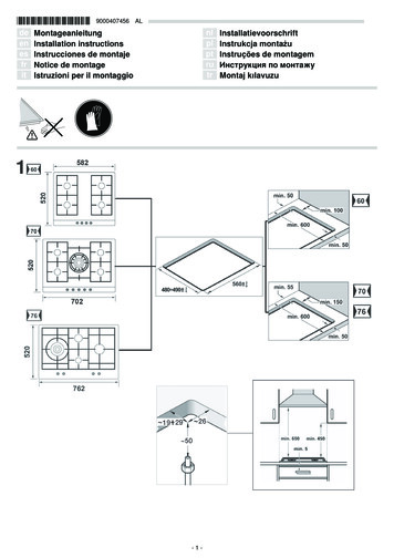
Features and Specifications5Installation Options Residential (not approved for HUD Mobile Homes) Raised or Floor Hearth Straight or Corner Placement Internal or External Chase Flush or Recessed Face 3 Blower Duct Locations Raised or Floor Placement 2 Electrical Connection LocationsHeating SpecificationsApproximate Heating Capacity (in square feet)* .Up to 3,000Maximum Burning Time.Up to 12 Hours*Heating capacity will vary with floor plan, insulation, and outside temperature.Dimensions8' Blower LeadWeight: 680 Lbs.See "ChimneyRequirements"Cooling ventshave an externaldiameter of 7"11-5/8"*24-1/2"*4-1/2"*CenterLine8' ElectricalInput Lead3-7/8"44"31-1/2"5"*1/2"Stand-offs24"1-1/2" Wide NailDown Flange46"6-1/2"Optional ElectricalConduit Exit Location8-1/8"*1"3-1/4"49"*26-1/8"*26-5/* Includes the1/2" stand-offs8"*The set-up face shipped on thefireplace is 44-1/8" wide and31-9/16" tall (dimensionsshown are for the finished face)6" Blower hook-ups are on both sides and on the bottom(centered 7" from the rear edge). Remove the cover plateto access the blower hook-up.Figure 1 Travis Industries415051193508093
6Installation(for qualified installers only)Packing List Grate Baffle Blower Assembly Ember Strip Log Retainer (includes hex wrench & instructions) Flex Duct w/ start collar – 3' Length, 6" Diameter (For Blower) Two 7” Start Collars (For Cooling Vents) Two 10' Flex Ducts, 7" Diameter (For Cooling Vents) Two Vent Hoods (For Cooling Vents) Two Vent Hood Storm Collars (For Cooling Vents) Faceplate Gasket Catalytic Temperature Reader (w. installation inst.)Items Shipped with the Faceplate Faceplate (two switch plate screws are attached) Switch Plate (includes blower rheostat) 10 Faceplate ScrewsItems Shipped with the Door(s) Owner's Manual Installation Hardware Pack Pair of Gloves Efficiency and Registration Cards Travis Industries415051193508093
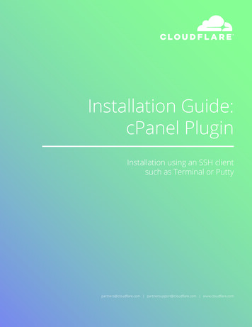
Installation7(for qualified installers only)Installation Overview All requirements below must be met.See the section"Chimney Requirements"See the section"MinimumClearances"See the section"Cooling Ve nt Requiremen ts"WARNING:Insulation must n ot fill thespaces between the stand-offs18" Min.See the section"Blower Requirements"See the section"Mantel Requirements"See the section"Facing Requirements"See the section"Hear th Requiremen ts"See the section"Minimum FramingDimensions"Figure 2Recommended Order of Installation Frame the opening for the fireplace. Make sure to allow for vent, blower, and cooling ventinstallation. Secure the fireplace to the floor. Install the vent, blower, cooling vents, and electrical hook-up. Complete the framing above the fireplace. Install the hearth. Install the facing. Install the mantel. Finalize the installation (see the instructions starting on page 28). Travis Industries415051193508093
8Installation(for qualified installers only)Installation Requirements for Cold EnvironmentsIf you live in the area depicted in black (see Figure 3),you must Install a cooling air “P” trap as detailed belowand install the blower on an internal wall. In addition,make sure the homeowner follows the requirementsshown below to help minimize cold air being pulled intothe fireplace when it is not in use.Figure 3Install the Blower in an Internal LocationInternal BlowerIn cold environments the blower must be positionedon an internal wall (see Figure 4). This eliminatesany chance of any outside air being drawn into theconvection chamber from the blower location.Exterior WallExteriorNOTE: Do not place the blower inside a garage orother area that may circulate fumes.FireplaceCooling Air “P” TrapInterior of HomeWhen installing the cold air ducts, make sure toinclude a “P” trap in the design (see the illustrationto the right). This helps slow cold air fromcirculating through the cooling air chamber.Figure 4Min. 24"Max. 48"Bi-Metallic DamperIn extremely cold environments the installer maywish to install a cooling air damper on the chimney.This component (part # 250-01741) is an 18”section of Duravent pipe that is installed at the topof the chimney, directly below the cap. It has aheat-activated damper that helps reduce cold airfrom entering the cooling ducts while the fireplaceis not in operation.Min. 24"Max. 48"FireplaceXtrordinairDaily Requirements for HomeownersFigure 5HumidityMake sure the humidistat is set correctly. The chart below details the correct setting for the temperatureyou are experiencing outdoors.Outdoor TemperatureRecommended HumidityController Setting F C-20-100 10 20 20-29-23-18-12-7 -7152025303540Note: If using a humidifier, let the homeowner know that it should be shut off or turned to a lower settingto eliminate condensation.Other Items Make sure the bypass is shut when the fireplace is not in use.Minimize the use of exhaust fans in the home when the fireplace is not in use. Travis Industries415051193508093
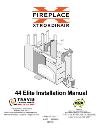
Installation9(for qualified installers only)Negative Pressure WarningThe Fireplace Xtrordinair wood fireplace relies upon natural convection to supply cooling air to thefireplace. If installed into a house experiencing negative pressure, air may be pulled into the fireplace.This leads to the face becoming cold while the fireplace is not in use, and in severe cases, air beingpulled into the room.What Causes Negative PressureToday’s air-tight homes are not 100% air tight. If air leaks are found at the top of the home enclosure, airmay be pulled through the home due to convection (the warmer air moves upwards, leaving the home,causing air to be pulled into the home from different location). See Figure 6 below.Air can be pulled down theRecessed lighting in ceilings may allow air to infiltratechimney, into the firebox.into the attic, leading to negative pressure.Heated air, leaving the house in cracksThe cooling air* can be heated by thenear the ceiling contribute to negativehouse, causing syphoning. This pullspressure.cool air through the cooling channel,leading to fireplace cooling.*Cooling air is required by the fireplaceDriers or range fansto prevent overheating.contribute to negativepressure.Negative pressure can cause airCracks near doors orto be pulled through the blower,windows can contribute tothrough the duct, through thenegative pressure.fireplace convection channel andinto the house.Figure 6How to Measure Negative PressureDigital pascal meters (also called “pressure meters”, digital “manometers”) can measure negativepressure readings inside a home. They typically cost around 600. They measure pascals (1 pascal isequal to .004” Water Column). Typical homes have 0 to -1 pascals. Homes with negative pressure have-2 or more (we have measured homes with upwards of -8 pascals). We strongly recommend measuringthe pressure in homes suspected of encountering negative pressure. This allows the homeowner, andfireplace installer, to view an objective measurement.How to Remedy Negative PressureThe only proven method to reduce negative pressure is to install an “air exchanger”. This device allowsoutside air to enter the home after going through a “heat exchanger” to minimize cold infiltration. Travis Industries415051193508093
10Installation(for qualified installers only)Fireplace Placement RequirementsMinimum Framing DimensionsA firestop is required at the top ofthe fireplace enclosure or ceilinglevel (whichever is lower).The fireplace enclosure must not beless than 81" above the base of thefireplace. If the fireplace is raised, theenclosure height must be raised tomaintain the 81". Do not build into this area. Do not slope the walls inward.Min. 4-1/2"We recommend installing theshaded framing membersafter installing the chimney.Arrange the framingmembers so there is not avertical member directly inthe center of the openingwhere it would interfere withpipe clearances.50-1/2"Header(install veritcally toensure proper pipe toheader clearance)26"NOTE: make sure theenclosure is wide enough toaccommodate the blower(see the section"Blower" fordetails).50"Figure 7Framing Dimensions at 45 Figure 8 Travis Industries415051193508093
Installation11(for qualified installers only)Fireplace Placement The fireplace must be secured to the floor (use the lifting handle brackets - see Figure 9).The fireplace (andfirebox) must be madele vel and plumb duringin stallation. Use shimsunder the fireplace toproperly level thefireplace.Travis Industriesrecommends the chasearound the fireplace beinsulated.WARNING:Insulation should beplaced between theframing members andsecured so it does not fillthe space between thefireplace and standoffs.ZeroClearanceCanStandoffs (alsolocated on back)FireboxWA RNING:Fai lu re to cor rectl y l evel and p lu mbthi s fi rep lace wil l lead to d oo rs thatswin g op en or cl osed . Lifting handles are availableseparately (98500711). Theyattach to the nail down brackets.Bend this bracket downon each side and nail itto the floor, securing thefireplace in position.Figure 9Fireplace must be placed directly on wood or non-combustible surface (not on linoleum or carpet)Fireplace must be installed on a level surface capable of supporting the fireplace and chimneyPlace the ember strip included with the fireplace below the front edge of the fireplace (see Figure10).EMBER STRIPINSTRUCTIONSThe ember stripinsures no ember fallsbetween the fireplaceand hearth onto thecombustible floor.Place this emberstrip under the frontof the fireplace andthe back edge of thehearth.NOTE: On the 36 Elite,the ember strip willneed to be shortened.Construct The Stand-Offs On Top OfThe FireplaceFigure 10Bend both standoffs as shown below. Remove the screw fromthe top of the fireplace and secure the standoff as shown below.The two standoff of top of the fireplace areshipped in the flat position. Bend them up andsecure as shown to the right Travis Industries415051193508093
12Installation(for qualified installers only)Clearances The fireplace uses 1/2" standoffs on the back and sides and 4" stand-offs on the top to space thefireplace away from framing members or walls. These stand-offs may contact the framing membersor walls but do not place insulation or other material in the space between the stand-offs andfireplace. When installed, walls in front of the fireplace must be a minimum 18" to the side of the faceplate (151/2” from the side of the fireplace). See Figure 2 on page 7. Fireplace should be located such that no doors, drapes, furniture or other combustibles can beplaced close or swing closer than the minimum 36" clearance. Due to the high heat output of thisfireplace, choose a location away from high traffic areas. Fireplace must be placed so the vents below and above the glass do not become blocked.Raised Fireplaces If the fireplace is raised, the fireplace enclosure must be raised as well (minimum 81” enclosureheight from base of fireplace see Figure 7). The fireplace (and hearth, if desired) may be placed on a platform designed to support the fireplaceand vent (approximately 600 lbs.). See Figure 11.Minimum 1" cement boardFaceplateFireplaceTile ormarbleNo combustible materialpermitted above this pointFireplaceElevated hearths must beconstructed of non-combustiblematerials such as cement blocks(6-1/2” Max.).Tile ormarble2 x 4 FramingEmberStripHeader height willneed to be increasedthis er height needs to beincreased this dimension.3/4"Plywood15"Raisedhearth2 x 8 FramingFigure 11 Travis Industries415051193508093
Installation13(for qualified installers only)Cooling Vent RequirementsWARNING: The cooling vents provide cooling air for the fireplace and chimney system. Failure tocorrectly install the cooling vents will lead to an extremely dangerous installation and possibly a fire. The two cooling vents must be installed so as toroute air from the outside to the two starter collarson the top rear corners of the fireplace. Secure thevents to the collars using high-temperaturealuminum tape and/or sheet metal screws.Included with the fireplace are two 10' lengths ofduct and two starter collars. Use a connector andseal if adding more duct length. Attach and seal both starter collars to the fireplaceas shown to the right.Use silicone to seal thestarter collar to the topof the fireplace.neicoSil Starter CollarsBend the tabs on thebottom of the startercollar up to lock it inplace. A maximum of two 90 bends may be used on each vent. However, if a 180 bend is placed directlyabove the starter collar, one additional 90 bend may be used (see Figure 12). The maximum distance for the cooling ducts is listed below:When the vertical rise is between:6' and 10' (max)3' and 6'1' and 3'0' and 1' Included with the fireplace isa set of storm collars andvent hoods. Place the collarsaround the vent on theexterior and attach withscrews or caulking to sealthe wall from the ventpenetration. Place the hood,with open portion facingdown, over the cooling ventsand secure.The cooling air ductterminations may be installedto draw air from a ventilatedcrawl space or attic ifapproved by local buildingcodes. NOTE: certain codesrequire a fire curtain damperin these cases.The duct terminations mustbe located so they can not beblocked (e.g. snow drifts).The duct terminations mustbe flashed and sealed tomeet local building coderequirements. Travis IndustriesThe maximum horizontal run may be:5'15'20'25'Cooling ventterminations mustterminate aminimum of 10'away from thechimneytermination.Air exits out of the outerliner of the alRunCrawl Space –See information to the left oncrawl spaces or attics.CoolingAirFigure 1293508093
14Installation(for qualified installers only)Blower RequirementsThe required blower pushes air through blower duct to the fireplace, where it is heated and distributedinto the room.Blower Duct Routing The blower may be located to draw air from the interior or exterior of the home (see Figure 13).NOTE: For cold environments, it must be located on the interior (see page 8).External BlowerInternal BlowerExterior WallExteriorExteriorExterior WallFireplaceFireplaceInterior of HomeInterior of HomeFigure 13 The maximum length for 6" diameter blower duct is 15' (use the included duct & start collar). The maximum length for 8" diameter blower duct is 25' (use two 6" to 8" adapters).NOTE: The shorter the blower duct, the greaterthe air flow.Caulk around allfour sides of theblower housing A maximum of two 90 bends may be used. The blower, if located on an external wall, mustbe weatherproofed (see Figure 14). Removethe blower cover and install the blower. Applycaulk around the perimeter of the blowerhousing where it contacts the external wall andvapor barrier (apply sparingly). Replace theblower cover.External Wall (&vapor barrier)BlowerCoverBlowerHousingFigure 14 The blower may be installed to draw air from acrawl space or attic if approved by localbuilding codes (see Figure 15). NOTE: certaincodes require a fire curtain in these cases. Do not draw air from confined areas or from agarage or area containing fumes or emissions.The blower inlet must be a minimum 36" belowany exhaust vent.The blower may be placedin a ventilated crawl space(if approved by the localbuilding department).Figure 15 Travis Industries415051193508093
Installation15(for qualified installers only)Blower Duct Connection Connect the blower duct to the right, left, or bottom of the fireplace. See Figure 16 for an overview.Using the Right or Left Side Blower Duct ConnectionRemove the side cover plate. Insert the starter section into the blower hook-up hole and bend the lockingtabs outwards, locking the starter section in place (see Figure 16).Using the Bottom Blower Duct ConnectionRemove the cover plate and pass-through plate on the bottom of the fireplace (both are held in place withthe same 4 screws). Remove the 8-1/2" by 6-1/4" air deflector (flapper) above the cover plate and securethe starter section to the 6” diameter hole above the air deflector (bend the locking tabs outwards, lockingthe starter section in place - see Figure 16). Replace the pass-through plate with the 4 screws removedearlier (the pass-through plate has a 6-1/2” diameter hole for the duct).TOPVIEWRing forduct11-3/8"Height: 13"Width: 11-3/8"Depth: 11-1/2"FRAMINGDIMENSIONS:6"NOTE:Older versions have a snap in connector(blue plastic) - simply connect the molexconnectors and snap in place.Hole forConduitNewer versions have a threaded conduitconnector - see illustration to the right.1-1/2"Molex ConnectorConduit Cover Plate(On both sides)Locking TabsThreaded Lock RingStart CollarBlowerHousingFireplaceXtrordinair13"6" BlowerHook-UpFlex DuctIntake grillmust beaccessible.Min. 4"Power Source(120 Volt A.C.)11 1/2"Attach the molex connectors(wings may be cut off to allowconnector to pass through)Figure 16 Use duct tape and/or screws to attach the flex duct to the starter collar and blower box. The blower utilizes a filter that requires periodic cleaning (see Figure 17). Show the homeowner the blowerlocation and inform them of the need to clean periodically.BlowerHousingFilter ScreenFilterIntake Grill1/4" NutdriverRemove the fourscrews that go intothese holes.Shake the filter to remove anydirt that may have accumulated.Figure 17Blower Electrical Connection Connect the electrical supply lead conduit to a 120 Volt, 60 Hz (2 Amp) electrical supply. Use a junction box toprotect the electrical connection (see Figure 16). Connect the blower conduit to the blower box by attaching the two molex connectors together. Insert the molexconnectors into the blower box. Then attach the conduit to the blower box by inserting it into the top until it snapsin place (see Figure 16). Do not run either conduit over the top of the fireplace or within 2" of the chimney If the blower or power supply is located to the left, the electrical conduit(s) may be directed to the left side of thefireplace. To do this, remove the conduit cover plate on both sides of the fireplace. Feed the conduit(s) throughthe hole on the right side and out the left side (removing the cover allows the conduit to be fed through withoutkinking). Switch the cover plates by attaching the right cover plate to the left side and vice-versa. Travis Industries415051193508093
16Installation(for qualified installers only)Chimney RequirementsApproved Chimney Use one of the following brands and series of chimney:- Simpson Duravent 8” x 12” (preferred – sold through Travis Ind. – see part numbers below)- Temco 82- Firecraft FTF8 (Superior TF8)- Superior/Astria/IHP 8DM- Marco 8D The entire chimney system must be installed to meet all local requiments as well as thoserequirements listed by the chimney manufacturer. Depending on the manufacturer and where thechimney is to be installed, chimney supports, roof braces, radiation shields, attic insulation shields,attic enclosures, spark arrestors, locking bands, etc. may be required as part of the chimneysystem. The manufacturer's installation instructions, which are reviewed by the listing agency,specifies when and where each of these components must be used. Follow the manufacturer'sinstructions for the use of flashing and an adjustable storm collar at the roof line to prevent water fromentering the house. Manufacturers require that chimneys extending beyond a certain height abovethe roof (frequently above 5') must be braced.Simpson Duravent Part Numbers (available through Travis Ind.)Chimney ComponentsPart #Starter Collar (REQUIRED)48” Chimney Section36" Chimney Section24" Chimney Section18" Chimney Section12" Chimney Section30 Offsets / Elbows (Qty 2)Firestop (90 )Firestop (30 - for angled sections)Storm CollarRound Termination CapFlashing 0-6/12 (for flat roofs up to 6/12 pitch - 26.5 )Flashing 7-12/12 (for roofs 6/12 pitch to 12/12 – 26.5 to 45 )Attic Insulation 119890001298900015Chimney Installation – Simpson Duravent (preferred) Simpson Duravent chimney requires a starter collar. Attach the starter collar to the top of thefireplace with four sheet-metal screws (see Figure 18). If the inner pipe is too tight, use a crimpingtool to adjust pipe diameter (see Figure 19). Seal the outer sections of pipe with high-temperaturesilicone.Simpson Duravent Starter CollarHigh-TSi emplic eon rae tureSKU 98900013 (required)NOTE: If the inner liner is too tight, use acrimping tool to reduce the diameter.Use high-temperature silicone toFigure 19seal the liner opening.Figure 18 Travis Industries415051193508093
Installation17(for qualified installers only)Chimney Offset Chart (Simpson Duravent) Use the chart below to determine offset dimensions (measured in inches).Chimney Installation – Non- Simpson Duravent Secure the inner and outer chimney liner to the fireplace (see Figure 20).The three brackets secure the outerchimney liner to the top of the fireplace.Position the brackets to the appropriateposition before securing.Outer Pipe BracketsInner Liner(ledge along inside acceptsvarious chimney pipe sizes)Connect the inner chimney liner tofireplace flue with three sheet metalscrews.Use sheet metal screws to attachthe brackets to the fireplace andchimney liner.Figure 20 When attaching the chimney to the fireplace, first slide down the inner liner of the chimney pipe intothe inner liner of the fireplace. Certain brands of chimney pipe will stop at the ledge, while others willinsert beyond the ledge. When the chimney
Cracks near doors or windows can contribute to negative pressure. Air can be pulled down the chimney, into the firebox. The cooling air* can be heated by the house, causing syphoning. This pulls cool air through the cooling channel, leading to fireplace cooling. *Cooling air is required by the fireplace to prevent overheating.