Transcription
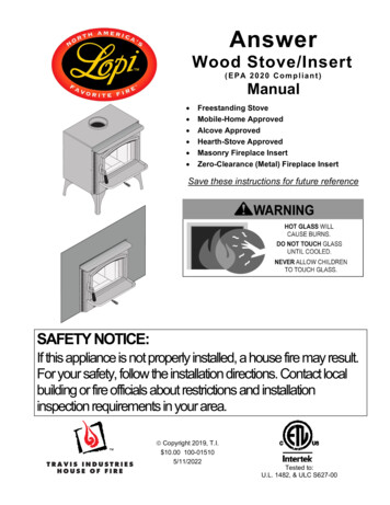
AnswerWood Stove/Insert(EPA 2020 Compliant)Manual Freestanding StoveMobile-Home ApprovedAlcove ApprovedHearth-Stove ApprovedMasonry Fireplace InsertZero-Clearance (Metal) Fireplace InsertSave these instructions for future referenceSAFETY NOTICE:If this appliance is not properly installed, a house fire may result.For your safety, follow the installation directions. Contact localbuilding or fire officials about restrictions and installationinspection requirements in your area. Copyright 2019, T.I. 10.00 100-015105/11/2022Tested to:U.L. 1482, & ULC S627-00
2IntroductionIntroductionWe welcome you as a new owner of a Lopi Answer wood-burning stove. In purchasing a Lopi Answeryou have joined the growing ranks of concerned individuals whose selection of an energy system reflectsboth a concern for the environment and aesthetics. The Lopi Answer is one of the finest appliances theworld over. This manual will explain the installation, operation, and maintenance of this appliance.Please familiarize yourself with the Owner's Manual before operating your appliance and save the manualfor future reference. Included are helpful hints and suggestions which will make the installation andoperation of your new appliance an easier and more enjoyable experience. We offer our continualsupport and guidance to help you achieve the maximum benefit and enjoyment from your appliance.Important InformationNo other Lopi Answer appliance has the same serialnumber as yours. The serial number is stamped ontothe label on the back of the appliance.Register your warranty online at:traviswarranty.comThis serial number will be needed in case you requireservice of any type.Model:Serial Number:Purchase Date:Lopi AnswerSave Your Bill of Sale.To receive full warranty coverage, you will need toshow evidence of the date you purchased your heater.We suggest that you attach your Bill of Sale to thispage so that you will have all the information you needin one place should the need for service or informationoccur.Purchased From: Travis Industries5/11/2022 - 1510Answer
Table of ContentsIntroduction .2Important Information .2Installation Options .6Features .6Heating Specifications .6Stove Dimensions .6Emissions .6Planning The Installation .7Preparation for Installation .7Additional Accessories Needed for Installation . 7Stove Installation Considerations .7Packing List .8Floor Protection Requirements .8Stove Placement Requirements .8Clearances – Singlewall Connector .9Clearances – Reduced Clearance Connector .10Chimney Connector Requirements .11Chimney Requirements .12Chimney Termination Requirements .13Outside Air Requirements .13Alcove Installation Requirements .143Carbon Monoxide (CO) Emissions .26Over-Firing the Stove .26Opening the Door. 27Before Starting a Fire . 27Adjusting the Burn Rate . 28Approximate Air Control Settings.28Understanding Your Heater’s Combustion System. 29Burning Your Heater . 29Optional Blower Operation . 30Re-Loading the Stove . 30Overnight Burn. 30Normal Operating Sounds . 30Hints for Burning . 31Selecting Wood . 31Why Dry Wood is Key .31Wood Cutting and Storage .31Do Not Burn List . 32Troubleshooting. 33Daily Maintenance (while stove is in use) . 34Remove Ash (if necessary) .34Clean the Glass (if necessary) .34Standard Ceiling with a Factory Built Chimney .16Cathedral Ceiling with a Factory Built Chimney .16Exterior Factory Built Chimney .17Hearth Stove Positive Connection .17Hearth Stove Direct Connection .18Interior or Exterior Masonry Chimney .18Monthly Maintenance (while appliance is in use). 35Planning The Installation .19Touch-Up Paint .36Cleaning the Air Duct and Blower (if applicable) .36Firebrick and Baffle Inspection .36Door Parts .37Replacing the Glass .37Replacing the Door Gasket .37Replacing the Door Handle .37Preparation for Installation .19Installation Considerations.19Packing List .19Insert Dimensions .20Fireplace Requirements .21Fireplace Altered Tag .21Insert Placement Requirements .22Masonry Fireplace - Hearth ExtensionRequirements .22Masonry Fireplace Requirements .22Zero-Clearance (Metal) Fireplace Requirements .23Drafting Performance .24Leveling Bolt Installation .24Insert with Positive Connection .25Insert with Direct Connection (Masonry Fireplace).25Safety Notice .26Before Your First Fire .26Verify the Installation .26Curing the Paint .26 Travis IndustriesDoor and Glass Inspection .35Door Adjustment .35Creosote - Formation and Need for Removal.35Yearly Maintenance . 36Firebox Parts . 38Floor and Side Firebrick Removal & Replacement. 38Air Tube Identification . 38Air Tube Removal & Replacement . 39Baffle Removal & Replacement . 40Listing Label . 42Rear Blower Installation (Part # 99000118) . 43Outside Air Boot Installation (Part number99200134) . 44Surround Panels . 45Front Blower (part # 99000123). 46To Switch The Power Cord To The Left Side: .46Installation Instructions .465/11/2022 - 1510Answer
4Safety PrecautionsThe viewing door must beclosed and latched duringoperation.Smoke from this appliance mayactive a smoke detector whenthe door is open.Never block free airflow throughthe air vents on this appliance.GasThis appliance is designed andapproved for the burning ofcordwood only. Do not attemptto burn any other type of fuelother than cordwood in thisappliance, it will void allwarranties and safety listings.Do not touch the appliance whileit is hot and educate all childrenof the danger of a hightemperature appliance. Youngchildren should be supervisedwhen they are in the same roomas the appliance.ASHESInspect the chimney connectorand chimney at least twicemonthly and clean if necessary.Creosote may build up andcause a house fire.Do not connect this appliance toany chimney serving anotherappliance. Travis Industries5/11/2022 - 1510OkTypeHTAshes must be disposed of in ametal container with a tight lidand placed on a noncombustible surface well awayfrom the home or structure.Keep furniture, drapes, curtains,wood, paper, and othercombustibles a minimum of 36"away from the front of theappliance.36"This appliance must be properlyinstalled to prevent thepossibility of a house fire. Theinstructions must be strictlyadhered to. Do not usemakeshift methods orcompromise in the installation.Gasoline or other flammableliquids must never be used tostart the fire or "Freshen Up" thefire. Do not store or usegasoline or other flammableliquids in the vicinity of thisappliance.ClayLinerContact your local buildingofficials to obtain a permit andinformation on any installationrestrictions or inspectionrequirements in your area.Notify your insurance companyof this appliance as well.This appliance must beconnected to a listed hightemperature (UL 103 HT)residential type chimney or anapproved masonry chimney witha standard clay tile, or stainlesssteel liner.Answer
Safety PrecautionsMobileHomeWhen installed in a mobilehome, this appliance must bebolted to the floor, have outsideair, and not be installed in thebedroom (Per H.U.D.requirements). Check with localbuilding officials.Never try to repair or replaceany part of this appliance unlessinstructions are given in thismanual. All other work must bedone by a trained technician.Do not make any changes ormodifications to an existingmasonry fireplace or chimney toinstall this appliance.Allow the appliance to coolbefore carrying out anymaintenance or cleaning.ThisManual5Do not place clothing or otherflammable items on or near thisappliance.This wood heater has amanufacturer-set minimum lowburn rate that must not bealtered. It is against federalregulations to alter this setting orotherwise operate this woodheater in a manner inconsistentwith operating instructions in thismanual.Overfiring the appliance maycause a house fire. If a unit orchimney connector glows, youare overfiring.Maintain the door and glass sealand keep them in goodcondition.Do not operate this heater withbroken or missing glass.Avoid placing wood against theglass when loading. Do notslam the door or strike the glass.Do not use a grate or otherdevice to elevate the fire off ofthe firebox floor. Burn the firedirectly on the bricks.Do not throw this manual away.This manual has importantoperating and maintenanceinstructions that you will need ata later time. Always follow theinstructions in this manual.Travis Industries, Inc. grantsno warranty, implied orstated, for the installation ormaintenance of yourappliance, and assumes noresponsibility of anyconsequential damage(s).Smoke and CO Detectors: Make sure your home has a working smoke detector, especially near any bedrooms. We recommendhaving a smoke and/or CO detector in the same room as the wood heater for additional safety.Proposition 65 Warning: Fuels used in gas, woodburning or oil-fired appliances, and the products of combustion of such fuels,contain chemicals known to the State of California to cause cancer, birth defects, and other reproductive harm.California Health & Safety Code Sec. 25249.6Travis Wood Burning Fireplaces, Stoves, and Inserts are protected by one or more of the following patents; U.S. 9,170,0254,665,889 as well as other U.S. and Foreign Patents pending.This wood heater needs periodic inspection and repair for proper operation. It is against federal regulations to operate thiswood heater in a manner inconsistent with operating instructions in this manual. Travis Industries5/11/2022 - 1510Answer
6Features & SpecificationsInstallation OptionsFeatures FreestandingFreestanding in an AlcoveFreestanding in a Mobile HomeMasonry Fireplace InsertZero-Clearance (Metal) Fireplace InsertSingle Operating ControlSteel Plate Construction (1/4" & 3/16")Heavy Duty Refractory FirebrickOptional High-Tech BlowerHeating SpecificationsApproximate Maximum Heating Capacity (in square feet)*750 to 1,400 (stove)750 to 1,200 (insert)EPA Tested Cord Wood BTUs per Hour**12,129 to 59,527Maximum Burn TimeUp to 8 Hours* Heating capacity will vary depending on the home's floor plan, degree of insulation, and the outside temperature.It is also affected by the quality and moisture level of the fuel.** EPA tests to determine BTU output are achieved with a single load of wood at each burn rate. At home, you arelikely to add more wood to your stove to maintain your desired comfort level. By the simple process of loading yourstove with additional wood, you could achieve up to a 20% higher heat output than established during EPA testing.This model was tested for efficiency using method B415.1-10 and was determined to have a weighted averageHigher Heating Value (HHV) Overall Heating Efficiency (OHE) of 72.4%. Overall efficiency of the heater may belower if the heater is operated without a heat exchange blower or with the installed heat exchange blower turned off.Stove Dimensions5-7/8”(149mm)6” (152mm) Dia.23-5/8”(600mm)3/4” (19mm)20”(508mm)20-3/4”(527mm)Height:27-7/8” (708mm)16-1/4”(413mm)IDB1016Figure 1NOTE: Measure all side, corner, and back clearances from the stovetop.EmissionsThis heater meets the 2020 U.S. EPA’s cordwood emission limits for wood heaters. Tested to EPA Alt-125,ASTM E3053-17, ASTM 2515-11, CSA B415.1-10 this heater has been shown to deliver heat at ratesranging from 12,129 to 59,527 BTU/hr and an emission value of 2.00g/h. Report No. 0028WS047E Travis Industries5/11/2022 - 1510Answer
Stove Installation (for qualified installers only)7SAFETY NOTICE:Please read this entire manual before you install and use your new room heater. Failure tofollow instructions may result in property damage, bodily injury, or even death. Contact localbuilding or fire officials about restrictions and installation inspection requirements in your area.Planning The InstallationWe suggest that you have an authorized Travis Industries dealer install your stove. If you install thestove yourself, your authorized dealer should review your installation plans.Check with local building officials for any permits required for installation of this stove and notify yourinsurance company before proceeding with installation.The location of your wood heater in your home will decide how effectively the heat produced will spreadthroughout your house. Attention to the home design with consideration of natural convection and aircirculation should be taken into account when choosing the placement of your heater within the home.Preparation for Installation Check for damage to the exterior of the stove (dents should be reported, scratches can be fixed byapplying touch-up paint). Check the interior of the firebox (replace cracked firebrick and make sure baffle is in place).The stove can be lightened by removing the firebricks and baffle (pg 38) - replace before operation.Additional Accessories Needed for Installation Legs (for stoves) or Panels (for inserts)Stove Installation ConsiderationsThe table below details the six most common types of installations and the considerations for each type.Alternative methods of installation are available if they comply with local building codes.Installation TypeConsiderationsStandard Ceiling with a Factory Built Chimney (Page 16)Cathedral Ceiling with a Factory Built Chimney (Page 16)Exterior Factory Built Chimney (Page 17)Hearth Stove Positive Connection (Page 17)Hearth Stove Direct Connection (Page 18)NOT APPROVED IN CANADAInterior Masonry Chimney (Page 18)NOT APPROVED IN CANADA Travis Industries Requires ceiling and roof penetrationProvides best draftCathedral style chimney support requiredProvides best draftUses two elbows to route chimney outsideExterior chimney is hidden from the roomElbows reduce draftOptional exterior chase reduces cold air blockageUtilizes existing masonry or zero clearance (metal)chimneyProvides good draft due to full relineEasier to clean than direct or horizontal hearth stoveUtilizes existing masonry or zero clearance (metal)chimneyRequires construction of a "block-off plate"Draft reduced due to elbows & chimney cross-sectionUtilizes existing masonry chimney (not approved forzero clearance (metal) fireplaces)5/11/2022 - 1510Answer
8Stove Installation (for qualified installers only)Packing List Wood Moisture MeterGlovesFloor Protection Requirements Stove must be placed on the Travis Industries legs. Floor protection must extend to the sides, rear, and front of the stove (see “Clearances” for minimumfloor protection).Floor protection must be non-combustible and at least .018" thick (26 gauge). No R value is required for floor protection - (R 0).Stove Placement RequirementsClearances may be reduced by methods specified in NFPA 211, listed wall shields, pipe shields, orother means approved by local building or fire officials. Stove must be placed so that no combustibles are within, or can swing within (e.g. drapes, doors), 36"(914mm) of the front of the stove If the stove is placed in a location where the ceiling height is less than 7' (2134mm), it must follow therequirements in the section “Alcove Installation Requirements” Must maintain the clearances to combustibles (drywall, furniture, etc.) shown in following illustrations: Travis Industries5/13/2022 - 1510Answer
Stove Installation (for qualified installers only)9Clearances – Singlewall ConnectorSTRAIGHT INSTALLATIONS(singlewall connector)NOTE: Measure rear and sidestove clearances from thenearest edge of the stovetop.16-1/2" (420mm)19-1/2" (496mm)NOTE: Measure front floorprotection from the face of thestove (unibody).US 6" (153mm)Can. 8" (204mm)23-5/8" (600mm)18" (458mm)5-7/8" (149mm)27" (686mm)16-1/4" (413mm)ConnectorApp. 6" (153mm) dia.TOP OF STOVEUS 6" (153mm)Can. 8" (204mm)US 16" (407mm)Can. 18" (458mm)IDB1164FLOOR PROTECTIONCORNER INSTALLATIONS(singlewall connector)Approx. 42-1/4" (1074mm)from Corner to Frontof Stove19-1/2" (496mm)US 6" (153mm)Can. 8" (204mm)23-5/8" (600mm)10" (254mm)5-7/8" (149mm)16-1/4" (413mm)ConnectorApp. 6" (153mm) dia.US 6" (153mm)Can. 8" (204mm)TOP OF STOVEUS 16" (407mm)Can. 18" (458mm)FLOOR PROTECTION Travis Industries5/11/2022 - 1510Answer
10Stove Installation (for qualified installers only)Clearances – Reduced Clearance ConnectorSTRAIGHT INSTALLATIONS(reduced clearance connector)NOTE: Measure rear and sidestove clearances from the nearestedge of the stovetop.9" (229mm)11-1/2" (293mm)NOTE: Measure front floorprotection from the face of thestove (unibody).US 6" (153mm)Can. 8" (204mm)23-5/8" (600mm)13" (331mm)5-7/8" (149mm)21-1/2" (547mm)Connector16-1/4" (413mm)App. 7" (178mm) dia.TOP OF STOVEUS 6" (153mm)Can. 8" (204mm)US 16" (407mm)Can. 18" (458mm)IDB1165FLOOR PROTECTIONCORNER INSTALLATIONS(reduced clearance connector)Approx. 38-3/4" (985mm) fromCorner to Front of StoveNOTE: Reduced clearanceconnectors may require anappliance adapter to connect to theflue collar.NOTE: Standard residentialinstallations with reducedclearance connector may use theclearance determined by themanufacturer of the connector forthe connector to wall clearance orthe clearance listed in this manual.Offsets must be used to maintainthe stove to wall clearance.NOTE: Vent diameter variesdepending upon brand and model.NOTE: Reduced clearanceinstallations require one of thechimneys and connectors listedbelow:16-1/2" (420mm)US 6" (153mm)Can. 8" (204mm)23-5/8" (600mm)7-1/2" (191mm)5-7/8" (149mm)16-1/4" (413mm)ConnectorApp. 7" (178mm) dia.US 6" (153mm)Can. 8" (204mm)TOP OF STOVEUS 16" (407mm)Can. 18" (458mm) AMERI-TEC model DCC with model HSchimney DURAVENT model DVL with DURATECor DURA-PLUS chimney GSW Super Chimney Twenty-Oneconnected directly to appliance I.C.C. Excel (2100-2 Can.) (103-HTUSA) chimney with ULTRABlackconnector METALFAB model DW connector withTG chimney OLIVER MACLEOD PROVENT modelPV connector with model 3103 chimney SECURITY model DP or DL connectorwith SECURITY model ASHT or S2100chimney SELKIRK METALBESTOS model DSconnector with model SSII chimney Standard Masonry Chimney with anyone of the above listed connectorsFLOOR PROTECTION Travis Industries5/11/2022 - 1510Answer
Stove Installation (for qualified installers only)11Chimney Connector Requirements Chimney connector is required from the flue collar of the stove to the factory-built chimney ormasonry chimney. The chimney connector must be 6” diameter and a minimum 24 gauge black steel, or one of thereduced-clearance connectors listed on page 10.NOTE: Aluminum or galvanized steel is not allowed – these materials can not withstand the fluetemperatures and may give off toxic fumes when heated.NOTE: Standard residential installations may use single-wall connector (Mobile-Homes may not). The chimney connector may not pass through a ceiling, attic, roof, closet, or any other concealedspace (use listed UL 103 HT chimney – see “Chimney Requirements for details). DO NOT USECONNECTOR PIPE AS CHIMNEY. IN CANADA: Where passage through a wall, or partition of combustible construction is desired, theinstallation shall conform to CAN/CSA-B365, Installation Code for Solid-Fuel-Burning Appliances andEquipment. The chimney connector should be as short and direct as possible. No more than 180o of elbows (two90o elbows, or two 45o & one 90o elbow, etc.) may be used for the entire system (connector andchimney). Horizontal runs should slope upwards 1/4” per foot and be a maximum 36” long. The chimney connector must be installed with the crimped end pointing downwards. This preventscreosote from leaking to the exterior of the pipe.IDB1117 The chimney connector must be fastened to the stove and each adjoining section (and chimney). Standard residential installations may use single-wall connector (Mobile-Homes may not) Standard residential installations with reduced clearance connector may use the clearancedetermined by the manufacturer of the connector for the connector to wall clearance or the clearancelisted in this manual. Offsets must be used to maintain the stove to wall clearance. Mobile homesmust use the clearances listed in this manual under "Additional Requirements for Mobile HomeInstallations". Travis Industries5/11/2022 - 1510Answer
12Stove Installation (for qualified installers only)Chimney Requirements DO NOT CONNECT THIS UNIT TO A CHIMNEY FLUE SERVING ANOTHER APPLIANCE. DO NOT CONNECT TO OR USE IN CONJUNCTION WITH ANY AIR DISTRIBUTION DUCTWORKUNLESS SPECIFICALLY APPROVED FOR SUCH INSTALLATIONS. IN CANADA: This appliance must be connected to a factory-built chimney conforming to CAN/ULCS629, Standard for 650 C Factory-Built Chimneys. UL 103 HT Chimney must be used from the first ceiling or floor penetration to the chimney cap. Use 6" diameter type UL 103 HT chimney from one manufacturer (do not mix brands) or codeapproved masonry chimney with a flue liner. Chimney must be fastened to each adjoining section. Follow the chimney manufacturer's clearances and requirements. Use the chimney manufacturer's fire stops, attic guards, roof supports, and flashings when passingthrough a ceiling (see “b” below). No more than 180o of elbows (two 90o elbows, or two 45o & one 90o elbow, etc.) may be used for theentire system (connector and chimney).NOTE: Additional elbows may be allowed if draft is sufficient. Whenever elbows are used the draft isadversely affected. Additional chimney height may be required to boost draft.b(a) M in. S yst em Height 15’M ax. S yst em Height 33’(b) Roof P enet rat ion and Term inat ion(S ee Chim ney M anuf act urer’s Req. )(c) Chim ney S ect ionscdbe(d) Ceiling P enet rat ion(S ee Chim ney M anuf act urer’s Req. )(e) M in. air space t o com bust ibles(S ee Chim ney M anuf act urer’s Req. - Typ 2”)(f ) Connect or - see “Chim ney Connect or” on t heprevious pageaffIDB1118DraftingPerformance Travis IndustriesFigure 2Draft is the force that moves air from the appliance up through the chimney. The amount ofdraft in your chimney depends on the length of the chimney, local geography, nearbyobstructions, and other factors. Too much draft may cause excessive temperatures in theappliance and may damage the heater. Inadequate draft may cause back puffing into theroom and plugging' of the chimney. Inadequate draft will cause the appliance to leak smokeinto the room through appliance and chimney connector joints. An uncontrollable burn orexcessive temperature indicates excessive draft.5/11/2022 - 1510Answer
Stove Installation (for qualified installers only)13Chimney Termination Requirements Must have an approved cap (to prevent water from entering). Must not be located where it will become plugged by snow or other material. Must terminate at least 3' (914mm) above the roof and at least 2' (610mm) above any portion of theroof within 10' (3.04M) - see Figure 3.Min. 2’ (610mm) Min. 3’ (914mm)10’ (3.04M)Min. 2’ (610mm) 10’ (3.04M)Min. 3’ (914mm)IDB1119Figure 3Outside Air Requirements Required for mobile homes & in certain localities (check with building officials). Must not be drawn from an enclosed space (garage, unventilated crawl space). May be drawn fromventilated crawl space (a) or exterior of home (d). Must have suitable rodent/debris screen and rainprotection (hood). Requires the optional outside air kit (sku# 99200139) or air boot (sku# 99200134 ). Air duct maximum length is 15’ (4.57M) with a minimum cross-section of 16 square inches(10323mm) or 6’ (1.83M) with a minimum cross-section of 7 square inches (4517mm).bcOutside AirConnectorOutside air entrance must be placed soit does not become blocked by snow. Travis Industries5/11/2022 - 1510aIDB1020Figure 4Answer
14Stove Installation (for qualified installers only)Alcove Installation RequirementsWhenever the stove is placed in a location where the ceiling height is less than 7' (2134mm) tall, it isconsidered an alcove installation. Because of the reduced height, the special installation requirementslisted below must be met. Chimney connector and chimney must be one of the following types:AMERI-TEC model DCC with model HS chimneyDURAVENT model DVL with DURATEC or DURA-PLUS chimneyGSW Super Chimney Twenty-One connected directly to applianceI.C.C. Excel (2100-2 Can.) (103-HT USA) chimney with ULTRABlack connectorMETALFAB model DW connector with TG chimneyOLIVER MACLEOD PROVENT model PV connector with model 3103 chimneySECURITY model DP or DL connector with SECURITY model ASHT or S2100 chimneySELKIRK METALBESTOS model DS connector with model SSII chimneyStandard Masonry Chimney with any one of the above listed connectorsNOTE: Reduced clearance connectors may not connect to the flue collar – an appliance adapter may be required. Alcoves are classified as combustible or non-combustible. Non-combustible alcoves must have wallsand a ceiling that are 3 1/2" (89mm) thick of a non-combustible material (brick, stone, or concrete).This non-combustible material must be spaced and ventilated at least 1" (25mm) off of all combustiblematerials (walls, ceiling, etc.) to allow air to move around the non-combustible walls and ceiling. Allother alcoves are considered combustible. The clearances below must be met:CombustibleAlcoveNon-CombustibleAlcove(a) Sidewall to stove13”(331mm)6”(153mm)(b) Backwall to stove9”(229mm)2”(51mm)(c) Connector tosidewall21-1/2”(547mm)14-1/2”(369mm)(d) Connector tobackwall11-1/2”(293mm)4-1/2”(115mm)(e) Maximum depth ofalcove48”(1220mm)48”(1220mm)(f) Minimum width ofalcove49-5/8”(1261mm)35-5/8”(905mm)(g) Minimum height ofalcove84”(2134mm)6”(153mm)above stove topIDB1015caNon-combustible alcoveconstruction (on wallsand ceiling) - see theexplanation above.Ventilatedair space Min. 3 1/2"(89mm) noncombustiblematerial1" (25mm)Min.CombustiblematerialsMiniumum ClearancedbIDB1121Non-combustiblereinforcergf Travis Industriese5/11/2022 - 1510Answer
Stove Installation (for qualified installers only)15Mobile Home RequirementsOutside air must be installed - see "Outside Air Requirements" on page 13 Chimney connector and chimney must be one of the following types:AMERI-TEC model DCC with model HS chimneyDURAVENT model DVL with DURATEC or DURA-PLUS chimneyGSW Super Chimney Twenty-One connected directly to applianceI.C.C. Excel (2100-2 Can.) (103-HT USA) chimney with ULTRABlack connectorMETALFAB model DW connector with TG chimneyOLIVER MACLEOD PROVENT model PV connector with model 3103 chimneySECURITY model DP or DL connector with SECURITY model ASHT or S2100 chimneySELKIRK METALBESTOS model DS connector with model SSII chimneyStandard Masonry Chimney with any one of the above list
Travis Wood Burning Fireplaces, Stoves, and Inserts are protected by one or more of the following patents; U.S. 9,170,025 4,665,889 as well as other U.S. and Foreign Patents pending. This wood heater needs periodic inspection and repair for proper operation.