Transcription
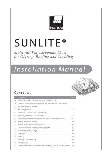
SUNLITE Multiwall Polycarbonate Sheetfor Glazing, Roofing and CladdingInstallation ManualCo nten t s :#ABCDEFGHIJKLMNOPChapterSUNLITE Product Structures and DimensionsChemical Resistance, Compatible Sealants and AdhesivesPositioning the SheetsArching RadiusWind and Snow Load CalculationSpacing and Load CalculationsPositioning of Clamping Profiles and Fastener LocationPreparation for GlazingPreparations Prior to InstallationGlazing Profiles and Fastening ScrewsHandling and StorageCuttingDrillingSealing and BondingAccessoriesGeneral Recommendations for Working with SUNLITE SheetsPage11122310111212131314141415
SUNLITE Installation ManualThis manual provides the basic information for working with and installing SUNLITE sheets. Due to their hollow core, priorpreparation is needed before the actual installation, with additional care during it. Please read the installation instructionscarefully before starting, and follow them meticulously.A - SUNLITE Product Structures, Dimensions and WeightsTable 1: Standard Products and DimensionsCellStructureProductTwin wallRectangularTriple wallTriple wallStructuredRectangularTunnelshapedX- LiteReinforcedThicknessmmin.Weightg/m2psf45 328000.1661 41,3000.2785 161,5000.31103 050419803985 161,7000.352,10082103 82,0000.411,830722,100821,80071165 321 1/43,7000.76351 3/83,9000.8098039Lengthmmft.2,000 to–12,0006.70 to– 39.4Notes:1. New products, updates & variants will be continuously added to SUNLITE product group. Confer with your local Palram dealer regarding thelatest product list.2. Length: Supplied according to customer need, up to 12.00m (39.40ft). Longer panels may be prepared upon stipulated special demand. Standardrecommended length up to 7.00m (23ft. approx.).B - Chemical Resistance (Compatible Sealants)SUNLITE has good resistance to many chemicals. Some chemicals may harm the SUNLITE sheets. Detailed information aboutthem can be found in PALRAM Industries, "Chemical Resistance of Polycarbonate Sheets". Please contact your PALRAM dealerwhen in doubt about any chemical.When choosing adhesives or sealants to be used during installation of SUNLITE sheets, please consult PALRAM’s brochure"Recommended Adhesives and Sealants for Polycarbonate Products", which is available on the PALRAMwebsite .For use of an adhesive or sealant not on the recommended list, consult with your PALRAM dealer to get his approval. Failureto do so will void any and all warranties.C - Positioning the SheetsA. SUNLITE sheets should be installed with the rib channels are sloping downwards (Figs. 1a, 1c, 2). That orientation will reduceaccumulation of dirt inside the sheet and ease gravity drainage of condensation moisture.RFigure 1bRFigure 1cFigure 1a1
SUNLITE Installation ManualB. Sheets should be installed with the adjoining edgesconnected by a glazing profile suited to the glazing system.gthlenslope 5%C. For sheets installed in the flat, horizontal position,(roofs, overhead skylights), a minimum slope of 5 percentis imperative, with 10 percent and above preferable.Steeper slopes offer better rainwater drainage andself-cleaning, and lessen the risk of water and dirtinfiltration through the connectors and fasteningscrews. They also help to diminish the visual effect ofsheet deflection caused by loading.widthwidthD. Length dimension is defined as parallel to the ribs, whilewidth is perpendicular to the ribs.Flat, two-sided clamped glazingFigure 2D - Arching RadiusSUNLITE sheets may be cold bent, or curved up to their minimum permitted radius, using polycarbonate’s natural properties,without need of a thermal process. Curving SUNLITE sheet beyond this minimum permitted radius induces undue stressesand strains in the glazing sheet, causing premature failure and will void the warranty.Table 2. Permissible Cold Bending Radii for Arched GlazingProductTwin wallTriple wallStructured(X-Lite)Thicknessmmin.45 321 465 1683 8105 1683 8105 8165 81612532 1 1/435 1 3/8Minimal permissible cold bending 1816.405,00019721.006,40025223.007000276E - Wind and Snow Load CalculationLocal building codes and standards in most countries provide details for required design loads, which should be consultedbefore installation. The information below is provided for general reference.Table 3. Conversion of Wind Velocity Values into Wind (or Static) PressureWindVelocityStatic -140( )33-4070-100( )14-20( )2
SUNLITE Installation ManualSnow Load: Snow load from accumulated snow cannot be disregarded. Both structure and glazing should be suitable forthis extra weight.In snow-bound areas, SUNTUF or SunSky single wall corrugated polycarbonate glazing is often preferable for roofingpurposes. Please consult with your PALRAM distributor.Indicative snow load:(per 1.0 cm, or 0.4 inch of height or thickness)Fresh, fine, fluffy snowfrom 0.8 to 1.9 kg/m2 (0.16-0.39 psf)Wet, watery, compacted snowfrom 2.0 to 8.0 kg/m2 (0.41-1.64 psf)F - Spacing and Load Calculations for Different Methods of InstallationA. Four Sides Clamp or FrameThis method utilizes comparatively small, separate glazing elements, cut from larger sheets. SUNLITE is put inside a foursided frame or supporting structures, and clamped on all sides. Clamping is done by plastic, wood or metal clampingprofiles, with or without rubber sealing strips, and fastened by nails, screws or bolts to the supporting frame. The frameitself can be made of wood or metal, according to the design.Clamping profileSilicone sealantRubber packing stripson both sidesSUNLITE glazingSupporting frameFigure 3aTypical four sided clamp installaion “wet” method, steel frame.Figure 3bbThe table on top the next page presents the recommended center-to-center spans, for each type of SUNLITE sheet at variouswind or snow loads.3
SUNLITE Installation ManualTable 4. Maximum Recommended Distances between Centers- Shorter Spans (width), under Different Ratios and Loads for Four SidesClamped / Framed Flat Glazing.Wind/snowuniform loadskg/m2psfSUNLITE 01001206Twin wall8108Triple wall10161625Structured(X-Lite)3235Distance between centers – shorter span, - according to ratio a:bRatio 1:1Ratio 1.5:1Ratio 5015001400135013001525142513751325Notes:1. SUNLITE 4mm twin wall is not included, since not recommended for constructive applications.2. Data in table according to load tests on typical multi-wall sheets and additional extrapolations.3. Recommended spans are calculated on the basis of 1/20 maximum deflection (5%) of sheet’s width (In this case crosswise, perpendicular to the rib channels).4. A SUNLITE glazing sheet may withstand even higher loads without buckling, however, excessive lateral shortening, created by higher deflection, may cause the edges toslip out of their supports (pop-out).Side clamp(glazing profile)SUNLITESUNLI glazingB. Two-Sided Clamped Glazing:This is a simpler glazing system to install, requiring no mid-sheet fastening,using long glazing sheets, and held in place by two glazing profiles on bothlongitudinal edges. It is not as strong, and permitted width is limited (thewidth direction of a multi-wall sheet is a more vulnerable to loads, spanwise, especially the thinner, square ribbed 6 , 8 and 10 mm sheets).Figure 4Flat, two-sidedclamped glazingSupporting rafterTable 5. Maximum Installation Distance for SUNLITE Sheets Using Two Sides Clamped Flat GlazingTriple wallSUNLITE sheetTwin wallUniform load61610168810kg/m2 psf mm in. mm in. mm in. mm in. mm in. mm in. mm in.X-Lite2532mm in. mm in.35mm 5030110043115045117546Note: The notes attached to Table 4. above also pertain to Table 5. here.4
SUNLITE Installation ManualClamping/Glazimg profileC. Two-Sided Clamped Arched Glazing:1. SUNLITE sheets can be curved into arches within the permitted radius(see paragraph V above), with no damaging effect to mechanical performance.Moreover, internal stresses induced by curving give it extra strengthand rigidity in both directions, like pre-stressed concrete elements.Curved SUNLITESheets2. Rigidity and the support spans increase as the curve radius is reduced(down to the minimal permitted radius). Shallow curve should beconsidered to be the same as flat panels, while a deep curve addssignificantly to the bridging ability.The following table shows the growing rigidity from the curving of SUNLITE,at various uniform loads.SupportingarchFigure 5Table 6. Maximum Recommended Spans between Arched Supports, According to Radius of Curveand Load for Two Sides Clamped GlazingSUNLITEsheetThickness Sheet curvatureRadiusmm6Twin wall8108Triple nded (center-to-center) Distance between Supporting archesaccording to wind/Snow loads below.mmin.mmin.mmin.mmin.Uniform wind/snow 0611550165065471200491250571450155061Notes:1. (-) A hyphen sign in the table appears when a certain sheet type cannot be used at the relevant range.2. Generally a span of less than 600 mm (24 in.) is impractical for this installation configuration.3. The lowest radius dimension (first in the column) appearing in the table, for each type of sheet, is the minimum permitted cold bending radius of that specific type.5
SUNLITE Installation ManualD. “Roofing and Cladding” Installation Method:This is a simpler, more practical method, resembling the one used for single-wall, corrugated plastic (or metal) sheets. Itemploys longer strips, with wider dimension. Length is as long as possible without excess deformation by thermal expansion.SUNLITE sheets are laid on top of the purlins, with rib channels directed down the slope, perpendicular to the purlins. Spanbetween purlins is determined by the load and deflection characteristics of the specific SUNLITE sheet.1. The sheets are connected to each other by long connecting elements.2. The wide variety of these connection methods falls into two maincategories: “wet” or “dry” installation systems. The connecting elements(made of aluminum, sheet metal or plastic- rigid PVC or polycarbonate)are designed as connectors, not as load supporting members. Theyconnect the sheets to each other, achieving one unified watertightexterior shell. Additional strength and rigidity achieved through them isan added bonus.Figure 6a. A basic inverted “H” polycarbonate connecting profile:An old and simple form enabling a lengthwise (side by side) connection between twin/multiwall sheets. It is sometime offered with a specific size profile for each sheet thickness, or in versatile,more flexible design enabling the use of one profile with 2 consecutive thicknesses (4-6 & 8-10 “H” profiles). This connectingmethod is practically inappropriate for the thicker SUNLITE panels.1) “Dry” method: The edges on both sides are inserted into the profile,holding the sheets by “dry” mechanical friction, with the sheets on bothsides fastened to the structure, along the purlins, by fixing screws, about500-600 mm (20-24 inches) apart.Figure 7. Basic, inverted H polycarbonateconnecting profile2) “Wet” method: both the profile channels are half-filled with silicone, whichacts, after installation and curing, both as sealer and adhesive. It may offer better weatherproofingat shallower slopes, than the “dry” system, but is very difficult to install properly and cleanly (Figure 7).Notes:a) The connector itself is not fixed to the purlins.b) Both systems are basic and disclose several shortcomings: difficult and bothersome installation, plain looks, weak and imperfect connection andsealing. Installation may prove to be lengthy and messy for inexperienced hands. They are, however, considered the cheapest.c) We would limit the use of “H” connector system to vertical, short sheets, as in wall cladding or windows.b. A two-part polycarbonate connecting profile comprised of:1) A lower base profile, usually the more rigid of the two, on which the edges of the adjoining sheets are placed. Usuallythe base profile is fastened to the purlins by screws through the middle, with both edges free, letting the sheets slide easilydue to the thermal expansion and contraction process.2) The upper part, usually more flexible than the base, clips on the base profile by hand pressure, holding both sides ofthe adjoining sheets in place by mechanical pressure.This type is easier to install, more reliable in holding the sheets and sealing the connection. It is used, mostly, in “dry”installation, but could be assisted by silicone on the upper and lower profile. “Wet” installation like this is difficult to keepclean during installation and with long sheets may lose its effectiveness due to excessive expansion.Figure 8aFigure 8bFigure 8cFigure 8. Drawing of typical two-part polycarbonate connecting profiles currently used6
SUNLITE Installation Manualc. Combination of metal and plastic two-part connecting profile offers added strength and rigidity. The lower part of the profileis made of metal- (mostly aluminum ), and the upper part is made of plastic (rigid PVC or polycarbonate), clipped on top of themetal profile, pressing on the edges of the two adjoining sheets.Figure 9. Depiction of Typical Two-Part Plastic and Metal Connecting Profiles Currently Usedd. Wood connecting profiles, developed from wooden window frames, support the installed SUNLITE sheets. They are usuallyused together with the “wet” system, with rubber packing strips and silicone sealant. Lengths are generally limited by the natureof wood. If long, laminated wooden rafters are used, they usually come with one or more of the other connecting solutions below.WoodAluminumSiliconeSealent“Dry” system“Wet” systemWoodRubber StripFigure 10. Depiction of Typical Two-Part Wood Connecting Profiles Currently used in the Markete. Metal connecting profiles comprise the largest group of connecting profiles. They come in wide variety of designs, are madefrom aluminum or steel, in “dry” or “wet” systems, and in plain or sophisticated detailing and finish. Some profiles are equippedwith built-in drains, EPDM rubber weather strips, concealed fixing screws, and high-end finish, for more luxurious structures.Silicone SealantSteel Clamping barEPDM Sealing/PaddingStrips Both SidesSteel SupportFigure 11aFigure 11bFigure 11cFigure 11dFigure 11. Depiction of Typical Two-Part Metal System Connecting Profiles Currently Usedf. Mid-Sheet Fasteners: (Not recommended for D.I.Y Applications)1) A wider sheet has to be fastened to the supporting structureby additional fastening along its width, as the connectorson both longitudinal sides are not enough to holdthe sheet down, against the uplift force it has to withstand.2) Fastening is usually done by screws, inserted along the supportinginternal purlins, spaced about 500mm (20in.) apart.Figure 12.Schematic Isometric View of PartialRoof Installation with Mid-sheet Fasteners7
SUNLITE Installation Manual3) Along the edge purlin, the fastening screws should be inserted about 300 mm (12 in.) apart.4) A hole must be pre-drilled into each screw location. The diameter of that hole should be 2 mm larger than that of thescrew, to allow for thermal expansion movements. In case of dark colored sheets predrill even larger holes, and use widerfastener washers.5) An electric screwdriver with an adjustable clutch should be used to tighten the screws. Avoid excess overtightening,which might induce undue internal stresses, causing premature failure and buckling of the sheet. Pay attention to insertthe screws perpendicular to the material face, as inclined insertion could damage the sheet and/or result in leaks.INCORRECT Excess overtighteningCORRECTFigure 13aFigure 13bINCORRECT Non-perpendiculardrilling and insertion.Self-tapping screwSelf-drilling screwFigure 13dFigure 13eWood screwFigure 13fFigure 13cFigure 13. Typical Installation Screws & Obligatory Washers25mm special washer/gasketFigure 13g6) Use of self-tapping or self-drilling screws is recommended. In case of wooden structures, suitable wood-screws shouldbe used. All the screws should be corrosion resistant, with at least heavy-duty hot-dipped galvanized finish, or stainlesssteel (if used in an extremely corrosive environment). The screws should be 6 mm (1/4 in.) diameter, with length accordingto sheet thickness, type of washer and type of supporting structure.7) Each screw should be fitted with a conical corrosion resistant steel washer, with specifications as the screws above orof aluminum, at least 1 mm (0.04 in.) thick, 25 mm (1 in.) diameter, with a Specially Shaped integral rubber gasket, EPDM(see PALRAM special washer/gasket fig. 13g). The screw should be tightened carefully, with no distortion of the washerand rubber gasket, or the flat face of the sheet PALRAM will suplly the suitable fasteners and washers with the SUNLITEsheets unless required otherwise.Figure 148) Screw buttons: Improved performance can be obtained by replacing the washerswith special plastic screw buttons, fitted with a suitable rubber gasket, with orwithout a closing cap. They fit the thickness of each type of sheet (6, 8, 10, 16mm, and possibly 25 mm), differing by sleeve length. Their advantage: the sleeveprevents excessive tightening and local squashing around the screw, and is softeron the sheet, reducing risk of tear or shear around the screw’s stem. They alsooffer a seal between the fastener hole and the open channels of the sheet, preventingpossible infiltration of water and dirt into the internal space of the sheet.Screw buttons work with the same screws mentioned above (6 mm,1/4 in.), maybe a little longer due to the higher thickness of the button.PALRAM recommends perforating SUNLITE for fastening as little as possible,and prefers the use of clamped edge installation. PALRAM recommendsthat the use of fastening screws in a glazing system, even with plastic buttons,should be limited to economical, price conscious projects only. Two or foursided clamped glazing is a preferred choice.8 30 mm 2 mm more thandiameter of button stemRubber gasketPlastic buttonFastenning screwOptional cover
SUNLITE Installation Manualg. Design spans between Supporting Purlins According to Designated Loads for the Roofing and Cladding Method:Table 7. Max. Recommended Spans between Support Purlins- Flat / Slightly Curved Roofing/GlazingDistance (center-to-center) between Supporting PurlinsProductTwin wallTriple ickness68108101616253235mmin.mmin.Uniform wind/snow loadskg/m2 psf kg/m2 Notes:1. Span calculation is based on general professionalknow-how, previous experience & specialized expertisewith this type of products.2. Spans depicted are educated estimations & extrapolationsbased on L/20 deflection (5%) at the specific span andload using continuos multi-span supports. The valuesrefer to mid-spans. Edge-spans (lower & upper ends)should be approx. 20% smaller.3. SUNLITE panels can withstand higher loads and/orwider spans without failure. but then deflections willincrease up to L/10 (10%) of the span, unacceptable inmost cases.Curving SUNLITE sheets gives them higher strength and rigidity, as in the case of two-sided clamped described below:Table 8. Max. Recommended Distances between Support Purlins, for Curved Roofing/Cladding, According to CurvatureRadius and Load.ProductThicknessRadius of sheetcurvatureMaximum recommended distance (center-to-center) between supportpurlins according to wind/snow loads belowmmin.mmin.mmin.mmin.Uniform wind/snow loadsmm6Twin Wall8108Triple 559
SUNLITE Installation ManualNotes for table on previous page:1. 4mm twin wall SUNLITE is not included, since not recommended for constructive applications.2. The specified spans are based on L/20 deflection (5%) at the specific span and load, using conyinuos multi-span supports. The values refer to midspans. Edge-spans (lower & upper ends) should be approx. 15-20% smaller.3. Spans depicted in all but the largest radii (6.00-8.00 m) derive from division of a full 180º barrel vault of the specific radius into equal size sectors.(For instance - an arch of 1.10m radius is divided into 2 equal parts of 1.73 m length. An arch of 1.50 m radius is divided into 3 parts each 1.57 mlong, and so on.)4. Curved SUNLITE is more rigid with a much wider span than in flat installation, especially in smaller radii. Rigidity & strength are reduced asthe radius as the radius is increased (for same type of panel). A lightly curved panel behaves almost the same as a flat one.SUNLITE glazingFigure 15. Schematic Description ofstandard curved roofing in a Vault.Supporting arched structureSupporting purlinsConnecting profiles fastened to purlinsh. General Notes for Structural Design:1) The recommended support spacing, as specified in the load/span tables, should not supersede the requirements oflocal structural and construction codes. The final values are to be dictated by actual conditions on site and engineeringdesign.2) The end spans, i.e. the distance between the edge support (or purlin) and the first internal purlin should be up to 80percent of the commonly recommended span for this load and type of sheet, or the value dictated by the design engineer.G - Positioning of Clamping Profiles and Fastener LocationA. Using the four-sided clamped glazing system, the support bars should be underneath (or inside), and the glazing clampson top (or outside). SUNLITE must be installed with the clamping profiles covering all four edges of the sheet. (Theseare load-bearing elements, which connect the glazing to the supporting structure, transferring loads from the glazingto it.)B. Using the two-sided clamped glazing system, the support bars (and glazing clamps) should be installed covering thetwo longitudinal edges of the sheet, parallel to the rib channels. (Again, these are load-bearing elements, connectingthe glazing to the supporting structure, transferring loads from the glazing to it.)C. Using the roofing/cladding method, glazing connectors (of any version) should be installed on both long sides of eachsheet (parallel to the rib channels). Their main duty is connecting adjoining sheets. They may assist transferring loadsto the structure, but here the fastening screws transfer most of the load to the supporting structure (the purlins). Thescrews, with their metal washer and rubber gaskets, should be inserted along the length of the supporting purlins, about500-600 mm (20-24 in.) apart and 300-400 mm (12-16 in.) at the edge purlin. When using metal glazing connectors,they are positively fastened to the purlins.When using polycarbonate connecting-profiles, some types are fastened and others do not. In that case, the fasteningscrews will be placed on both sides of the connector, about 200-250 mm (8-10 in.) on each side.10
SUNLITE Installation ManualH - Preparation for GlazingA. Determination of Rabbet Depth and Thermal Expansion Allowance:These parameters depend on the SUNLITE sheet dimension, and relate to the four sides of the sheet (four-sides clampedsystem), or to the two edges parallel to the rib channels (two-sides clamped system).1. Allowance for expansion:SUNLITE expands about 3 mm for every meter (1/8 in. per 3 1/3 ft.) of length (or width) for a service temperature rangeof about 50 C (90 F), the practical working range in most cases. For a sheet of 1.00 m (or 40 in.) wide, 1.50 m (60 in.)long, a net allowance of 3 mm (width) and 5 mm (length) should theoretically suffice. We recommend doubling thisallowance for practical reasons. Allowance should be divided between both sides of the sheet. When the ends of panelsare protected by a recessed 'U' channel, allow suitable internal space for thermal expansion.2. Edge Engagement: (the overlap of the glazing over its frame).3. Rabbet Depth: (expansion allowance edge engagement). PALRAM recommends a rabbet depth of at least 20 mm(0.8 in.) for widths up to 1.0 m (40 in.) and a depth of 25-30 mm (1.0-1.2 in.) for wider spans.Wooden frameFastening screwababTop aluminumglazing profileRubber sealingprofile/gasketSilicone sealantSUNLITE sheetsSUNLITE sheetsa - Expansion allowanceSealing gasketb - Edge Engagement depthBottom aluminumglazing profilec - Rabbet depth: a bWoodenclampingFigure 16aprofile“Wet” GlazingRubbersealingstripFigure 16b“Dry” GlazingFixing screwsSupportingsteel beamefAcBbdBA-A12faeA12fa. Sheet widthb. Sheet lengthc. Sash (frame) widthd. Sash lengthe. Edge Engagement depth (overlap)f. Thermal expansion allowanceg. Rabbet Depth e 12 fB-BFigure 16c. Schematic Sketch of Rebbet depth and Expansion Allowance. (”wet” and “dry” methods)11
SUNLITE Installation ManualI - Preparations Prior to InstallationA. Ensure smaller thermal expansions by installing sheets - especially colored sheets - at ambient temperatures of 10-25deg. C (50-77 deg. F). It is generally recommended to avoid installing sheets at colder or hotter temperatures.B. Peel off the protective film at both open ends of the sheet (the width sides) to about 80-100 mm (3.5-4 in.) from the edgesof the sheet, to enable taping of the aluminum sealing tape. If a factory installed temporary seal is taped over the openends, it should be removed prior to the installation of the aluminum tape. Tape the sealing tape straight along the openend side, so it will cling well and evenly to both sides of the sheet, making sure that all the open ends of the rib channelsare properly sealed.C. Peel off the masking along the edges of length sides, both sides of the sheet, for about 80-100 mm (3.5-4 in.) from theedges, preparing the sheet for the insertion into the connecting profiles or the glazing frame.D. Remove the underside masking just prior to the actual installation on the roof. Premature removal of protective filmmay result in damage to the sheet during handling.E. Remove the upside, exterior protective film as soon as the installation of the whole glazed area is completed, or veryshort time afterwards. Failing to do so, exposing the protective film to direct sunlight, may fuse it to the sheet’s face andcause difficulties in removal, due to deterioration of the film, and void the warranty.Impermeablempermeablepermeable tapeVentilatedVentilateVentilat filter tapeFigure 17a.Partial or CompleteRemoval of Protective FilmPrior and after InstallationU-protectiveend capFigu
Installation Manual (per 1.0 cm, or 0.4 inch of height or thickness) from 0.8 to 1.9 kg/m2 (0.16-0.39 psf) from 2.0 to 8.0 kg/m2 (0.41-1.64 psf) Snow Load: Snow load from accumulated snow cannot be disregarded. Both structure and glazing should be suitable for this extra weight.