Transcription
QRail System QClick Technology Rail Mounting SystemRESPECT THE ROOFInstallation Manual
Table of Contents1. Introduction.11.1 Short Description.11.2 About this Manual.11.3 Warnings.11.4 Regulatory Information.31.5 Safety.42. Technical Description.52.1 System Overview.52.2 QRail Components.62.3 Technical Data.72.4 System Electrical Bonding.82.5 System Electrical Grounding.123. Important Mounting Information.143.1 Conditions of Use.143.2 Mounting Preparations.143.3 Mounting Aids and Required Tools.153.4 Fastener Torque Settings.154. Planning the Module Area.165. Installation of Roof Attachments and Rails.175.1 Select QRail Configuration.175.2 QRail Preparation.185.3 QRail Installation on Roof-top.205.4 End Caps.226. Module Installation.236.1 Module Level Power Electronics Installation.236.2 Installing Mid- & End-Clamps with QClick Technology .246.3 Installing the End Modules.256.4 Installing the Inner Modules.276.5 Installing Additional Module Rows.277. Maintenance.297.1 Inspection.297.2 Testing.298. List of UL2703 Evaluated and Approved Modules.309. CAD Part Drawings.33
1. Introduction1.1 Short DescriptionThe QRail PV mounting system is a strong, versatile system for mounting PV modules on low and steep-sloped roofs. Thesystem consists of aluminum module support rails and includes all necessary components in order to attach the rails toeach other, to attach the rails to the roof attachement, and to attach the modules to the rails; it also includes other variousaccessories, such as module level power electronic (MLPE) attachments and a skirt system. The system allows modules tobe mounted in portrait or landscape and can also be configured for shared rail and fixed tilt design in either orientation. Itaccommodates most framed modules. Bonding is fully integrated into the QRail system.1.2 About This ManualThis manual describes the installation of the QRail mounting system and provides necessary information regardingcomponents, system planning, and important safety warnings. Sections 1, 2, and 3 provide an overview as well as detailedinformation about the QRail system and components. Section 4 provides basic module layout and planning information.Sections 5 and 6 provide detailed system assembly and installation instructions. Section 7 provides maintenancerequirements, and the last remaining section provides detailed information on UL 2703 evaluated and approved modules.It is important that you carefully read these Instructions as well as all applicable documents prior to carrying outany installation, maintenance, or disassembly work. These instructions provide you with the information requiredfor the safe and complete installation, maintenance, and disassembly. Should you have any questions, pleasecontact Quick Mount PV at tech@quickmountpv.com or at 925-478-8269. Please refer to our website for furtherinformation and details at www.quickmountpv.com.1.3 WarningsThe following warnings are used in these Installation Instructions to indicate safety-related information.They include: Warning symbols (pictograms) Signal words which identify the hazard level Information about the type and source of the hazard Information about the potential consequences in case of the hazard being disregardedMeasures for the prevention of hazards and the prevention of injuries or damage to property.The signal words of the warnings respectively indicate one of the following hazard levels: DANGERIndicates a potentiallymortal danger, disregard forwhich may result in seriousinjury or death.BI 7.2.3-46WARNINGCAUTIONIndicates a potentiallydangerous situation whichmay result in serious injuryor damage to property.Indicates a potentiallydangerous situation whichmay result in minor injuriesor damage to the property ifignored.1ATTENTIONIndicates potential dangerwhich can result in damageto the property.Jan-2020, Rev 7
Installation PersonnelThe QRail system and these instructions are intended for use by qualified personnel. Qualified personnel are those who haveskills, knowledge, and training in the installation of photovoltaic mounting systems necessary to follow these instructions inorder to safely use the required tools and to carry out the required procedures.Intended UseThe QRail system is intended for use only as a mounting system for photovoltaic panels and certain associated hardwareand components. Any other usage or usage outside the intent or scope of these instructions is considered not as intendedand may result in forfeiture of the system warranty. Please contact Quick Mount PV with any questions regarding theserequirements.General Safety WarningsRisk of fatal injury due to falling. Falling from the roof can result in serious injuries or death.DANGER Please wear and use proper protective equipment Secure yourself against falling Do not perform any work in strong windsRisk of fatal injury from falling objects. Parts falling from the roof can result in serious injuries ordeath. DANGERBefore beginning the installation, please ensure that proper safety precautions are observed,only authorized personnel are permitted in and around the construction area and properprotective clothing and equipment are worn.Risk of injury from damage due to roof excessive loads can severely damage the roof and causeinjury.DANGER Before mounting and installation, please make sure that the buildings and especially the roofmeet the increased structural requirements of the PV system and the installation operations.Material damage due to incorrect installation. Incorrectly mounted clamps are a hazard to theintegrity of the PV system. PV modules can fall and be damaged.CAUTIONBI 7.2.3-46 Mount all clamp connections in accordance with the instructions.2Jan-2020, Rev 7
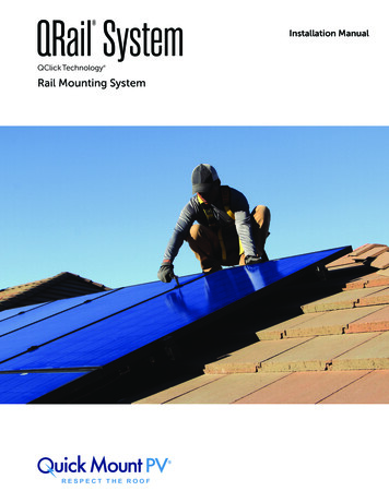
1.4 Regulatory InformationANSI / UL 2703The QRail system is ETL listed to UL 2703, Edition 1. Listing documents are available from thewebsite: www.quickmountpv.com. For additional information, contact Quick Mount PV.UL 2703 requires that listed PV systems be labeled to indicate their compliance with UL 2703.The QRail system includes labels affixed to the QRail End Clamps as shown in image 1.4.1.Fire Class Resistance Rating (ANSI / UL 2703)The QRail system is intended for roof mounting over a fire-resistant roof covering rated for the application. The QRail firerating is valid for the following: Class A for Flush Mounted Steep Slope Applications when using Type 1 or Type 2, Listed Photovoltaic Modules w/o QSkirt Class A for Flush Mounted Steep Slope Applications when using Type 1 or Type 2, Listed Photovoltaic Modules w/ QSkirt Class A for Flush Mounted Low Slope Applications when using Type 1 or Type 2, Listed Photovoltaic Modules w/o QSkirt Class A for Flush Mounted Low Slope Applications when using Type 1 or Type 2, Listed Photovoltaic Modules w/ QSkirt Class A for 5 and above Tilt Mounted Low Slope Applications when using Type 1 or Type 2, Listed Photovoltaic Modulesw/o QSkirtClass A for 5 and above Tilt Mounted Low Slope Applications when using Type 1 or Type 2, Listed Photovoltaic Modulesw/ QSkirtThis fire class rating requires installation procedures, which are in compliance with the included instructions. The QRailsystem is intended for roof mounting over a fire-resistant roof covering rated for the application. The QRail fire rating is validfor all roof slopes for Flush Mounted Systems and roof slopes equal to or less than 7 (11/2:12) for Tilt Mounted Systems. Thefire class rating is valid for systems installed at any height above the roof deck, with or without optional skirt. Grounding & Bonding (ANSI / UL 2703)This racking system may be used to ground and/or mount a PV module complying with UL 1703 only when the specificmodule has been evaluated for grounding and/or mounting in compliance with the included instructions.Mechanical Load Rating (ANSI / UL 2703)The QRail system has been mechanically tested according to UL 2703Edition 1 to the following load ratings: Downward Pressure: 10 PSF Upward Pressure: 5 PSF Down-Slope Load: 5 PSFMarking (ANSI / UL 2703)5012866ANSI/UL 2703 require the presence of a label indicating the system Fire Class Ratingor information directing the user to the appropriate information. The QRail Fire ClassRating label is located on each End Clamp as shown in Image 1.4.1.BI 7.2.3-463QRail by Quick Mount PV Patent 9,147,986Conforms to UL STD 2703Fire Rating: see installationmanual for requirementsMFR: XXXXImage 1.4.1QRail label placementJan-2020, Rev 7
1.5 SafetyAll generally applicable safety regulations for Quick Mount PV products can be viewed in the General Installation Manual.Please read this document carefully and adhere to the instructions and procedures therein – use the system only for itsintended purpose and follow both the general and specific safety instructions. In addition, please observe the specific safetyinstructions which precede the process steps in the present product-specific Mounting Instructions.Safety Ratings:BI 7.2.3-46 Maximum 300 modules per ground lug Maximum size of modules: 22.31ft2 Maximum system voltage is 1500 VDC Maximum Fuse Rating: 20A4Jan-2020, Rev 7
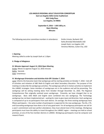
2. Technical Description2.1 System OverviewThe following is an overview of the major QRail system components as shown in Image 2.1.1.Note that the actual configuration of each individual system can vary depending on: Type of roof (substructure and roofing) Type of module Number of modules and configuration Local conditionsbecadImage 2.1.1a Roof attachmentb QRailc Mid clampd End clampe Internal QSplice (not visible)BI 7.2.3-465Jan-2020, Rev 7
2.2 QRail System ComponentsComponentsProduct RenderingTorque ValueQRail options:Standard in various lengthsLight in various lengthsMill or Black finishInternal QSplice:For Standard & Light QRail sizesFixed Size End Clamps w/ QClick Technology :For modules from 31-50mm thickMill or Black finish8ft-lbf (11N-m)Universal End Clamps w/ QClick Technology :2 clamps for modules from 30-45mm or 38-50mm thickMill or Black finish8ft-lbf (11N-m)Hidden End Clamps9ft-lbf (12N-m)Universal Bonding Mid Clamps w/ QClick Technology :2 clamps for modules from 30-45mm or 38-50mm thickMill or Black finish12ft-lbf (16N-m)T-bolt:16ft-lbf (22N-m)QMR-GLQ Grounding Lug:Can be installed in any rail channelWire capture bolt:6-8 AWG: 60in-lbs (7N-m)10-12 AWG: 36in-lbs (4N-mT-Bolt:For attaching roof attachments, MLPEs, and grounding lugsto the rail16ft-lbf (22N-m)End Cap options:For Standard & Light QRail sizesBlack finishBI 7.2.3-466Jan-2020, Rev 7
2.3 Technical DataApplicationLow and steep slope roofsRoofing typeSuitable for most types of roofing3Roof slopeUp to - 45 1 (upto 12:12)Building heightUp to 60 ft / 18.25 m1PV modulesFramedModule orientationLandscape or portraitSize of module arrayAny size possible1Position of the module arrayNo special requirements1Distance between roof attachmentpointsUp to 10 ft / 3 m1Maximum Rail Cantilever1/3 maximum allowable span for project1Codes & Standards³IBC/IRC 2018IBC/IRC 2015IBC/IRC 2012ICC-AC428 2012ASCE 7-05ASCE 7-10ASCE 7-16CBC/CRC 2016CBC/CRC 2019ANSI/ UL 2703 Ed. 1FBC/FRC 2017Aluminum Design Manual 2010, 2015SEAOC PV2 - 2012, 2017Supporting profilesExtruded AluminumSmall partsStainless steelColorMill or Black finishWarranty25 years2Different maximum values may apply, depending on site, building, choice of roof attachment and module type. Refer to QRail Code Compliance lettersor site-specific engineering.2Limited product warranty. Download full warranty on www.quickmountpv.com.³Grounding and bonding of mounting system to metal roof panels shall meet local AHJ requirements.1BI 7.2.3-467Jan-2020, Rev 7
2.4 System Electrical BondingThe QRail system, when properly assembled and installed, provides an integrated electrical bonding path, ensuring thatall exposed metal parts and the PV module frames are electrically connected. The QRail employs a number of features toensure reliable electrical connectivity.Bonding and Fault PathImages 2.4.1 and 2.4.2 show the available current path(s) in the QRail system for standard (2 or more rails per row ofmodules) and shared rail configurations, respectively.Images 2.4.4 through 2.4.15 provide detail drawings of the labeled connection points.2.4.1 Standard configuration bonding path (two rail system shown)Bonding mid clampInternal bonding spliceStandard end clampCopper ground conductorEnd clamp w/ WEEB-BMCHidden end clampQMR-GLQ Grounding lug2.4.2 Shared configuration bonding pathAlternate module bonding deviceNOTE!The QRail Hidden EndClamp is not NOT a bondingsolution and thereforein the case of orphanedmodules, an alternative listedmodule grounding device inconjunction with all rails beinggrounded must be utilized. SeeDiagram 2.4.3. Alternatively,use Universal End Clampswith WEEB-BMC installed perdiagram 2.4.10.BI 7.2.3-462.4.3 Orphan module configuration bonding path8Jan-2020, Rev 7
Bonding with QClick Technology As shown in Image 2.4.4 and 2.4.5, the QRail Clamps with QClickTechnology and rails are designed with sharp hooks. When the clamp isinstalled in the rail and the bolt is tightened, the bolt forces the hooksinto the rail. Then, as the clamp engages the module and the bolt istightened to the recommended torque specification [12 ft-lbf (16 N-m)for Mid Clamps and 8 ft-lbf (11 N-m) for End Clamps], these hooks arepulled into the QClick channel and penetrate the aluminum oxide orpainted coating on the rail and electrically bond to the rail, clamp, andbolt. A serrated flange bolt head serves to electrically bond the bolt to thebody of the mid or end clamp, thus forming a secure electrical bondingpath as shown in Image 2.4.6.hooksImage 2.4.4Clamp hooksImage 2.4.5Clamp hooks and railPV Module BondingPV module frames are electrically bonded to the QRail system by the bonding mid clamps. Bondingmid clamps are preassembled and bonded with stainless steel bonding pins below the clamp head.The stainless steel bonding pins pierce the oxide of the PV module, forming an electrical bondbetween the module, the clamp head, and thus to the rest of the QRail system. Bonding mid clampsImage 2.4.6are available in either mill or black finish.Clamp bonding pathUniversal height end clamps may be converted to bondingversion by adding optional bonding clips (WEEB-BMC-11).Bonding versions of the end clamps are useful when mountinga single module or in shared rail configuration where bondingmid clamps are not utilized. The WEEB-BMC-1 is a stainlesssteel bonding clip formed with spikes that pierce the oxide ofthe clamp head and the PV module, forming an electrical bondbetween the module, the clamp head, and thusto the rest of the QRail system.Image 2.4.7Bonding plate mid clampImage 2.4.8Fixed end clamp[12 ft-lbf (16 N-m)][8 ft-lbf (11 N-m)]Image 2.4.9Universal end clampImage 2.4.10-1Universal end clampw/WEEB-BMCNOTE!The installer is responsible for and shall provide an appropriatemethod of direct-to-earth grounding according to the latestedition of the National Electrical Code, including NEC 250:Grounding and Bonding and NEC 690: Solar PhotovoltaicSystems.The QRail Hidden End Clamp is NOT a bonding solutionand therefore in the case of orphaned modules, an alternativelisted module grounding device in conjunction with allrails being grounded must be utilized. See Diagram 2.4.3.Alternatively, use Universal End Clamps with WEEB-BMCinstalled per diagram 2.4.10.[8 ft-lbf (11 N-m)][8 ft-lbf (11 N-m)]WEEB-BMC -1 is evaluated as an alternative component and maybe used interchangeably with a WEEB-BMC Bonding Clip.1BI 7.2.3-469Jan-2020, Rev 7
Rail Bonding with Internal QSpliceAll QRails can be spliced into longer units by means of the QRail InternalQSplice (Image 2.4.11). The bonding splice joins the two rail segmentsmechanically and electrically for the Standard and Light rails.The Internal QSplice has a bonding plate that pierces any paint or aluminumoxide layer on the rails. This forms an electrical bond from rail-to-rail throughthe bonding plate. The splice body is electrically bonded through the bondingplate and the rivet that secures the bonding plate.QRailInternalQSplicebodyRivetBonding plateImage 2.4.11 QRail Internal QSpliceBI 7.2.3-4610Jan-2020, Rev 7
Roof Attachment BondingThe QRail is attached to the roof by roof attachments.Image 2.4.12-1T-boltThe connection from the attachment device to the rail is made via a stainlesssteel T-bolt and a stainless steel, serrated flange nut (Image 2.4.12-1 and 2.4.122). When secured to the rail [16 ft-lbf (22 N-m)], the T-bolt crushes and piercesthe aluminum oxide or paint and forms an electrical bond with the rail. Theserrated flange nut pierces the coating on the roof attachment and forms anelectrical bond that carries through the T-bolt and the rail.Full engagement of T-bolt is confirmed when the alignmentindicator line on the end of the T-bolt is vertical.INCORRECTCORRECTImage 2.4.12-2L-foot / Rail / T-boltWARNINGModule Level Power Electronic (MLPE) or Accessory BondingThe QRail is attached to a MLPE with the same stainless steel T-Bolt and stainless steelserrated flange nut used for the roof attachment. (Image 2.4.11-1). When secured to the rail[16 ft-lbf (22 N-m)], the T-bolt crushes and pierces the aluminum oxide or paint and formsan electrical bond with the rail. The serrated flange nut pierces the coating on the MLPEbracket and forms an electrical bond that is carried through the T-Bolt to the rail.CAUTIONUse only 20mm long T-bolts whenmounting Module Level PowerElectronics (MLPE) to top of rail. PlaceMLPE in a location on the rail thatreduces the risk of contact with themodule backsheet under load.Image 2.4.13T-bolt in QRailImage 2.4.14T-bolt in QRail with MLPEinstalledNOTE!Roof attachments and accessories are outside the scope of UL2703 on grid interactive PV systems. QRail is attached to the roofutilizing compatible roof attachments. See our website at www.quickmountpv.com for applicable roof attachments.Image 2.4.15MLPE mounted to QRail withT-bolt.BI 7.2.3-4611Jan-2020, Rev 7
2.5 System Electrical GroundingArray Grounding LugThe QRail system is listed to UL 2703 with the QMR-GLQ Grounding Lug as themeans to connect the QRail array to the Equipment Grounding Conductor (EGC).It is the system installer’s responsibility to determine the appropriate wire size forgrounding the array.To ease and facilitate the process of bonding and grounding the array, it isrecommended that these steps are accomplished after the roof attachmentsand rails are in place prior to module installation. The QMR-GLQ Grounding Lugis a special, preassembled lay-in lug designed specifically for use in bonding thearray segments (module rows) electrically and for connecting the bonded array toground. The QMR-GLQ Grounding Lug is shown in Image 2.5.1:a Lugb Wire capture boltc M8x20 T-head boltd M8 serrated flange nutbacdImage 2.5.1QLug Groundling Lug componentsT-bolt:16ft-lbf (22N-m)Wire capture bolt:6-8 AWG: 60in-lbs (7N-m)10-12 AWG: 36in-lbs (4N-mWhen the PV modules are properly installed, the QRail QClick bonding clamps ensure thatall the exposed metal parts and the module frames in each module row or array segmentare integrally electrically connected (bonded) with a high-ampacity bond. Each modulerow must also be connected to ground through the system ground electrode. This isaccomplished by using QMR-GLQ Grounding Lug to bond each of the array segments ormodule rows together and for connecting the entire array to the ground electrode. Thisarrangement is shown in Image 2.5.2.It is the installer’s responsibility to determine the correct wire type, size, and temperaturerating for the particular array. The wire sizes and capacities, which can be accommodatedby the QMR-GLQ Grounding Lug, are shown in Table 2.5.1 on the next page.NOTE!The QRail QSplices have been evaluated and listed to UL2703; therefore, a spliced rail can be treated as a single solidrail. Additional QMR-GLQ Grounding Lugs or bonding jumpersare not required for spliced rails within the thermal breakguidelines.When using a WEEB-Lug 8.0 see our supplemental instructionsBI 7.2.3-4612Image 2.5.2Array bonding connections at eachmodule rowJan-2020, Rev 7
QMR-GLQ Grounding Lug InstallationThe QMR-GLQ Grounding Lug is preassembled with a M8-T-bolt,serrated flange nut, and a wire capture bolt. The lug can be installedin the top or side channel of the QRail rail in any orientation.AWG Wire SizeQMR-GLQ Capacity12 - 61 wire102 wires122 wires Insert T-head bolt head into the rail’s top or side channel. Be sureTable 2.5.1to allow the bolt head to rotate as far as possible in the T-boltGrounding Lug wire capacitychannel to ensure full engagement of the bolt head with the sidesof the channel. Tighten M8 nut to [16 ft-lbf (22 N-m)]Using the above procedure, install a QMR-GLQ Grounding Lug oneach segment of the array. Once all the QMR-GLQ Grounding Lug areinstalled, use a continuous length of wire to connect each rail by layingwire in the lug wire channel and secure with the wire capture bolt.Torque to 60in-lbs (7N-m) for a 6-8 AWG wire or 36in-lbs (4N-m) for a10-12 AWG wire.Image 2.5.3Lug installed in side channelArray GroundingThe bonded array segments must be connected to the system ground electrode usinga single continuous copper wire. This is achieved by routing the grounding cablethrough the QMR-GLQ Grounding Lugs on each array segment. (Image 2.5.3 and 2.5.4)Galvanic ReactionATTENTIONCautionBI 7.2.3-46When dissimilar metals come into contact, it is possiblethat they will react with each other and cause corrosionin one or both of the metal surfaces. Aluminum andcopper are particularly reactive with each other;care must be taken to prevent any contact betweenaluminum components and bare copper wire (Image2.5.3 and 2.5.4).Image 2.5.4Lug installed in top channelPlace QMR-GLQ grounding lug in a location on the top ofthe rail that reduces the risk of contact with the modulebacksheet under load. Side channel installs may also beused to further reduce risk.13Jan-2020, Rev 7
3. Important Installation Information3.1 Conditions of UseThe QRail on-roof system is available with different rail and roof attachment types designed in accordance to and/orcompliance with the following codes and standards¹: IBC/IRC 2018 IBC/IRC 2015 IBC/IRC 2012 ICC-AC428 2012 ASCE 7-05 ASCE 7-10 ASCE 7-16 CBC/CRC 2016 CBC/CRC 2019 ANSI/ UL 2703 Ed. 1 FBC/FRC 2017 Aluminum Design Manual 2010, 2015 SEAOC PV2 - 2012, 2017¹Check code-compliance letters for applicable approvals.Risk of injury from damage to roof, Excessive loads can severely damage the roof and cause injury. DANGERBefore mounting and installation, please make sure that the building and especially theroofing meet the increased structural requirements of the PV system and the installationoperations.Risk of fatal injury from falling objects. Parts falling from the roof can result in serious injuries ordeath. DANGERBefore beginning the installation, please ensure that proper safety precautions are observed,that only authorized personnel are permitted in and around the construction area, and thatproper protective clothing and equipment are worn.The design of each system should be verified using QRail Code Compliance letters or site-specific engineering. Pleaseobserve the constraints listed in Section 2.3, “Technical Data.”3.2 Mounting PreparationQuick Mount PV recommends you ascertain the local conditions and requirements before ordering the QRail. In particular,acquaint yourself with: The roof structure and any irregularities Dimensions, material, quality, and spacing of the rafters Type, quality, and attachment method of the roofing.BI 7.2.3-4614Jan-2020, Rev 7
3.3 Mounting Aids and Required ToolsIn addition to standard hand tools, you will need the following tools: 1/2" or 13mm socket / 1/2" or 13mm box or open-end wrench Drill driver Torque wrench Reciprocating saw and/or band saw Chalk line Tape measure 5 mm Allen key / 5 mm Allen key power driver (for fixed end clamps only)Please adhere to the mounting steps listed and be sure to follow the safety instructions. DO NOT use an impact gun.DO NOT use an impact gunon QRail components.WARNING3.4 Fastener Torque SettingsProper torque is important to a safe and secure installation. Please refer to Section 2.2 QRail Components for recommendedtorque values for the various fasteners in the QRail system. Unless specifically directed otherwise, these values should beused for all metal-to-metal attachments.BI 7.2.3-4615Jan-2020, Rev 7
4. Planning the Module AreaFor installation, the QRails are fastened to thebuilding structure with roof attachments (e.g. flashedroof attachments). The roof attachments must bemounted at defined distances, depending on thespacing of the supporting structure, the position onthe roof, and the site conditions. The design shouldbe verified using QRail Code Compliance letters orsite-specific engineering.bedca Height of the module field: Number of modulesvertically x module length ( any clearances)b Width of the module array:aUsing standard end clamps : [number of moduleshorizontally x module width] [number of 17mm(11/16in) module gaps] [2 x 1.2 in (30.5mm) toaccount for rail extending beyond modules].fUsing hidden end clamp: [number of moduleshorizontally x module width] [number of 17mm(11/16 in) module gaps].c Vertical spacing of the base rails: Refer to modulemanufacturer’s acceptable clamping zones or mounting point locations.Image 4.1Module Aread Horizontal attachment point spacing: Dependent upon roof attachment method and site-specificparameters.e Distance between the modules 17mm (11/16 in)f Distance between module rows 0.25 in. minimum, no maximum distance provided gap does not result in snow dammingRisk of fatal injury due to falling. Falling from the roof can result in serious injuries or death.DANGER Please wear and use proper protective equipment. Secure yourself against falling. Do not perform any work in strong winds.Risk of fatal injury from falling objects. Parts falling from the roof can result in serious injuries ordeath.DANGERBI 7.2.3-46 Block off the hazard area on the ground prior to beginning work to prevent falling objectsinjuring persons. Ensure that no parts can fall off the roof. Please wear required protective equipment. Do not linger in the hazard area. After completion of the installation, re-check area for loose objects and re-check for properattachment of racking and modules.16Jan-2020, Rev 7
5. Installation of Roof Attachments and QRailsThe roof attachments are attached to the roof structure and support the QRails. The permissible distance between theroof attachments depends on several factors and must be calculated specifically for each project. Roof attachments areavailable for a wide variety of roof types. In many cases, additional items may be required to accomplish flashing or otherweather sealing. Suitable products are available from a number of sources. It is the responsibility of the installer to select theappropriate products and to install them correctly.5.1 Select QRail ConfigurationStandard Rail ConfigurationImage 5.1.1-1 shows a typical standard rail configuration. In this configuration, arow of modules is supported by two rails under each row of modules. In areas withexceptionally high snow or wind loads it may be necessary to support the modules withthree rails, image 5.1.1-2. Can be installed in both flush mounted or at an angle to theroof. See the QRail Tilt Supplemental Installation Guide at quickmountpv.com.Shared Rail ConfigurationThe rail design of the QRail system allows the use of sharedconfigurations for the Standard rail with standard mid and end clamps.In this configuration, a single rail supports two rows of modules asshown in Image 5.1.2. Shared rails may be used for both landscapeand portrait array configurations. See the Shared Rail SupplementalInstallation Guide at quickmountpv.comImage 5.1.1-1Two-rail configurationModified Shared Rail ConfigurationModified shared rail configuration is a hybrid of standardand shared rail configurations, image 5.1.3. The first and lastrail are set back from the end of the modules in standardmodule clamping zones to provide additional adjustabilitywhile the remaining rails are in shared rail configuration.This configuration maintains the benefits of shared railconfiguration using the same clamps, 25% less rails, and fullarray bonding. May be used for both landscape and portraitmodule orientations. See the Shared Rail SupplementalInstallation Guide at quickmountpv.comImage 5.1.1-2Three-rail configurationNOTE!Image 5.1.2Shared rail configurationWhen selecting QRail configuration, insurethe modules have the appropriate ratingsfor the project site conditions in the selectedconfiguration. Check the module installationmanual to determine if the clamping area fallswithin the acceptable range for the project designloads.Precise rail positioning and alignment is criticalwhen installing shared rail systems. Roofattachments which are adjustable in the N-Sdirection are recommended when installingshared rail systems.BI 7.2.3-46Image 5.1.3Modified shared rail configuration17Jan-2020, Rev 7
5.2 QRail PreparationThe QRail internal QSplices are used to join two rail sections to provide a single rail section of a desired length.Internal QSplice Installation The internal QSplice is a floating splice, no attachmentsnecessary. To join any rail using the Internal QSplice, join the rail sectionsby sliding the splice into the end of the rail until the bondingplate tabs come into contact with the end of the rail. Slide the other rail onto the splice until the end of the rail comesin contact with the bonding plate tabs. Make sure that bothrail ends are tight against bonding plate tabs. Image 5.2.6When re-installing the QRail Internal QSplices, insert the splicebackwards for optimal performance.NOTE!The QRail QSplices are
Mechanical Load Rating (ANSI / UL 2703) The QRail system has been mechanically tested according to UL 2703 Edition 1 to the following load ratings: Downward Pressure: 10 PSF Upward Pressure: 5 PSF Down-Slope Load: 5 PSF Image 1.4.1 QRail label placement ANSI/UL 2703 require the presence of a label indicating the system Fire Class Rating


![bTBiesaFn Ep k BIsðèl EdleyIgsmnwgTTYl - calfund [.] org](/img/39/preschool-toolkit-cambodian.jpg)