Transcription
Scale Manufacturers AssociationLoad CellApplication and TestGuidelineApprovedApril 2010Scale Manufacturers AssociationPO Box 26972Columbus, Ohio43226-0972Phone: (866) 372-4627E-mail: info@scalemanufacturers.orgWeb: www.scalemanufacturers.org
Load Cell application and Test GuidelineTable of ContentsSection1Purpose2Scope3Introduction to Load Cells4Load Cell Specifications5Test ProceduresAppendicesI Comparison of load cell specificationsII Load cell functional testingIII Load cell TerminologyReferencesThe following individuals, representing the membership of the SMA, contributed to this standard:Cardinal Scale Manufacturing CompanyHBM Inc.HobartMettler-Toledo Inc.Mettler-Toledo Inc.Revere Transducers Inc.Tedea-Huntleigh Inc.Avery Weigh-Tronix Inc.Steve PatorayJeff RobidouxNigel MillsDarrell FlockenTom LeahyJan KerstenQuenton OlsonKevin Fruechte
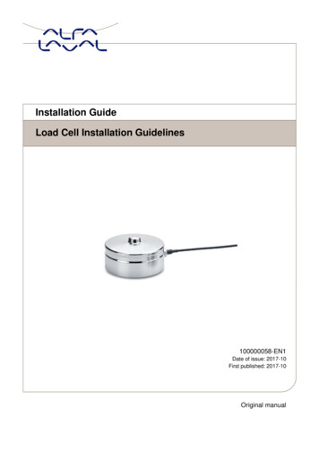
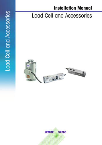
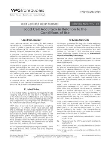
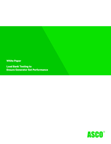
1.Purpose1.1. It is the purpose of this guideline to promote greaterunderstanding between manufacturers and users of loadcells by establishing uniform terminology, method ofspecification, and test procedures for load cells.1.2. A primary objective of the standard is theestablishment of simple and readily understandabledefinitions. As much as possible, terminology has beendefined in a manner such that the term can be expressedquantitatively and in a straightforward manner.1.3. It is also an objective of the standard to establish acommon term or title for each performance characteristicrelating to load measuring devices. Where several termspertaining to the same definition are in common usage,preference will be indicated by listing the definitionsunder the preferred term.3.Introduction to Load Cells3.1. A load cell is a device that is used to measure weightor force. W hen a force is applied to it in a specificmanner, a l oad cell produces an output signal that isproportional to the applied force. Strain gage load cellsare at the heart of the majority of weighing and forcemeasurement devices produced today. One end of a loadcell is typically supported on a rigid structure while theother end supports a load-receiving device throughwhich the load or force is applied. L oad cells can beused individually or in combinations in weighingdevices, as dictated by the geometry of the object to beweighed.3.2. Strain gage load cells are by far the most commonform of load cell commercially available today, and arebriefly described here. F igure 1 illustrates a t ypicalmetallic foil strain gage.1.4. All terms for which a definition has been provided,with the exception of “load” and “load cell”, are shownbold throughout to facilitate referencing the definitions.1.5. It will be noted that the term “accuracy” has beenused sparingly since its meaning has become too general.When applied to measuring devices, this term isconfusing since it is seldom known which specific errorsare included.2.Scope2.1. This standard provides recommended terminologyand definitions pertaining to load cells used forperforming accurate measurement of weight and force.Figure 1: Metallic foil strain gage2.1.1. Whenever possible the terminology anddefinitions have been established to apply as broadly aspossible to all load cells regardless of technologyemployed. However, the main focus has been on stressor strain sensing load cells and specifically strain gageload cells and terminology pertaining exclusively toother load cell types (mechanical, hydraulic, pneumatic,etc.) has not been included.This consists of a metallic foil etched into parallel gridlines forming a ci rcuit between the solder pads that areused to complete the circuit. T he foil is bonded to aninsulating backing material that, in turn, is bonded to thesurface of the load cell, as shown in Figure 2. A Straingage type load cell consists of a spring element that isselectively weakened to create regions of relatively highstrain; this is where the strain gages are applied.2.1.2. The terminology and definitions in thisdocument refer to load cells only. No attempt has beenmade to cover related instrument systems terminology.2.1.3. It is recognized that there is additionaltransducer terminology that could apply to load cells.However, the list of definitions in Appendix III haspurposely been limited to those terms frequently usedand necessary in the general use and application of suchdevices.Figure 2: Strain gage arrangement on a load cell
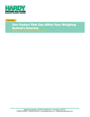
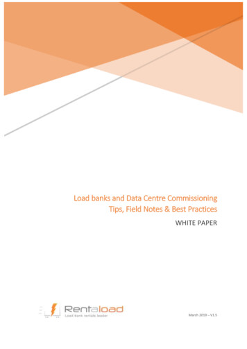
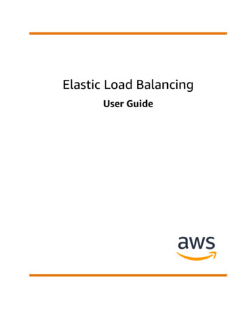
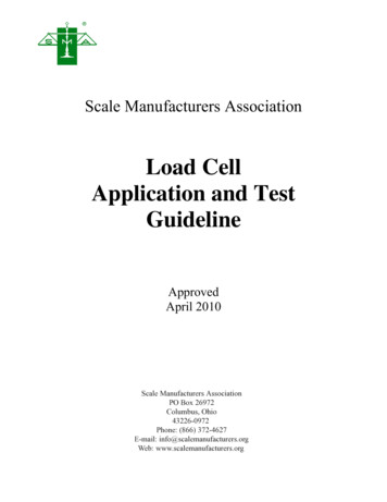
In Figure 2, two gages are illustrated on the top surfaceand two corresponding gages on the bottom surface arenot shown. I n this arrangement two gages measuretensile strains and two measure compressive strains asload is applied to the load cell (indicated by the letters Tand C respectively in Figure 2). The strain gages arewired together to form a Wheatstone bridge, asillustrated in Figure 3.Figure 4: Canister type load cellFigure 3: Wheatstone bridgeNote that several other resistors are typicallyincluded in the circuit, for example, a resistor may beadded to temperature compensate the cell’s performance,these are not shown for simplicity. A stable excitationvoltage is applied to opposite corners of the Wheatstonebridge, and a signal is measured across the others,points A and B in Figure 3. With no load applied to thecell, all gages have the same resistance and hence thereis no voltage difference between points A and B. Asload is applied to the cell, the resistance of the tensiongages increases, while that of the compression gagesdecreases. The bridge now becomes “unbalanced” and avoltage difference (signal) proportional to applied loadcan be measured across points A and B. E lectronicweight indicators are readily available which, at theirmost basic, supply the excitation voltage for the bridge,measure the output signal, and provide a digital displayof the applied load. Some load cells and indicators haveprovision for sense wires as shown in Figure 3 whichallow the indicator to measure and adjust for the actualexcitation voltage applied to the cell, this is particularlyimportant with long cable runs.3.3. Several mechanical configurations of load cell haveevolved for different applications; here is a b riefdescription of the most common:3.3.1. Figure 4 illustrates a t ension canister cell, andFigure 5 illustrates a typical S-beam, the arrows indicatethe direction of applied loading.Figure 5:S-beam load cellThese are often used in tank and hopper weighing, wherethe load cells are suspended from an overhead structureand the object to be weighed is hung from the underside.The S-beam is also widely used in the conversion ofmechanical scales to electro-mechanical; in this situationthe cell is used to sense the tension in the steelyard rodconnecting the lever system to the beam. Typicalcapacities range from 100 l b to 50,000 lb for tensioncanisters, and 25 lb to 20,000 lb for S beams.3.3.2. Figure 6 illustrates a co mpression canister cell;Figure 7 illustrates a low profile compression disk cell,while Figure 8 illustrates a r ocker column cell. T hesecells are cylindrical in shape and used in compression
applications. The relationship of the distance betweenthe bearing points of contact and the spherical radius ofthe bearing surface determine self-restoring alignmentcharacteristics of this design approach. Other load cellssuch as canister and S-beam geometries can also beadapted for use in a rocker configuration to improveaccuracy in certain scale designs.Figure 8: Rocker column load cellFigure 6: Canister load cellAll of these cells are used in vehicle scales. The rockercolumn is designed so that it will return to an uprightposition after the deck has been disturbed laterally,eliminating the need for check rods. T he canister anddisk cells are also used in tank and hopper scales.Typical capacities range from 500 l b to 500,000 lb forcompression canisters, 1,000 lb to 100,000 lb forcompression disks, and 1,000 lb to 200,000 lb for rockercolumns.3.3.3. Figures 9 and 10 illustrate two forms of doubleended shear beam.Figure 9: Double-ended shear beamFigure 7: Compression disk load cellThe cell illustrated in Figure 9 is supported at its centerwhile the load is suspended from the ends through linkshanging from the “ears”. This cell is typically used invehicle scales. F igure 10 illustrates a s imilar cellsupported at each end while the load is introduced at thecenter.
Single point cells differ from the other cells describedthus far in that it is moment insensitive, meaning that itreads the same regardless of where the load is applied tothe upper platform. Capacities typically range from 2 lbto 4,500 lb and can accommodate platform sizes up to 48inches square.3.4. Load Cell DeflectionFigure 10: Double-ended shear beamFor vehicle scale applications the load is typicallyintroduced through a link hanging at the center. T hiscell is also used for tank and hopper weighing, in whichcase the load is introduced at the center through a clamparrangement that also provides lift off protection.Double-ended shear beams typically range in capacityfrom 1,000 lb to 250,000 lb.3.3.4. Figure 11 illustrates a single ended beam that iswidely used in floor scales and tank and hopperweighing.All load cells are subject to stress due to the load appliedand are therefore subject to strain as described above inthe strain gage section. T here is a n ecessary deflectionassociated with a given strain. Load cell deflection atrated capacity can vary from a f ew thousandths of aninch up to a tenth of an inch or perhaps more. Theweighing system designer must consider a number offactors related to load cell deflection or stiffness. Thereare two factors involved in load cell stiffnessconsiderations:The spring equation or Hooke's law relates the forceexerted by a spring to the distance it is stretched by aspring constant, k, measured in force per length:Where F is the force of the applied gross load, k is thespring constant and δ is the cell displacement. Thefundamental resonant frequency of a spring/mass systemwith the load cell as spring and the gross load applied tothe spring as mass is given by:Figure 11: Single-ended beamThe load can be introduced through a rocker pin or balland cup arrangement. There are many configurations ofsingle ended beams, with capacities typically rangingfrom 10 lb to 50,000 lb.3.3.5. Figure 12 illustrates a single point load cell thatis widely used in small platform scales.LoadFigure 12: Single point load cellWhere f is the resonant frequency (Hz) and M is theapplied gross mass. Combining the two equations, weget the useful formula:Where g is the acceleration due to gravity in appropriateunits.The weighing system designer needs to consider thetradeoff involved in the inverse relationship betweenresonant frequency and deflection.A stiffer cell will provide a higher resonant frequencyfor the system. T his higher resonance will allowimproved better settling and filtering characteristics withpotentially shorter times to an accurate weight (for acheck weigher for example). A stiffer cell is, however,more difficult to protect from shock and overloadconditions.
4.Load Cell Specifications4.1.Load cells are available with various accuracylevels to suit an array of industrial and legal for trade(LFT) weighing applications. A LFT application is onewhere the load cell or scale is used in commercialtransactions to determine the charge for goods orservices rendered. The performance requirements forLFT load cells are well defined in standards that areadhered to within the weighing industry. There has beenconsiderable progress in recent years in rationalizing therequirements for LFT load cells across the World; hereis a d escription of two of the more widely acceptedstandards.4.1.1. Specifications, Tolerances, and Other TechnicalRequirements for Weighing and Measuring Devices(better known as Handbook 44) is the document used byWeights and Measures jurisdictions as the basis forexercising control over scales (and hence load cells) inthe USA and some other countries, notably in Centraland South America. H andbook 44 c lassifies weighingapplications into accuracy classes I, II, III, III L, and IIIIin descending order of accuracy requirements.Commercially available load cells are usually of class IIIor III L; retail and industrial applications generally fallinto class III, while vehicle, railroad track, and hopperscales fall into class III L. Load cells are furtherclassified by the maximum number of load cellverification intervals for which they are suitable, and asbeing suitable for single or multiple load cellapplications. T he tolerances applied to “multiple” cellsare looser because of the partial cancellation that can beexpected when two or more cells with normallydistributed errors are summed. The classification for aload cell is often presented in an abbreviated fashionwhere the maximum number of load cell verificationintervals is stated in units of 1,000, and “single” and“multiple” are abbreviated to S and M respectively.Thus, the classification for a cell could be stated as classIII L 6 M (load cell suitable for class III L applicationswith a maximum of 6,000 divisions, and employingmultiple cells). I n the USA there is a National TypeEvaluation Program (NTEP) which tests scales and loadcells for compliance with the provisions of Handbook44, and issues a Certificate of Conformance normallyreferred to as an NTEP certificate. T he majority ofstates in the USA require scales used in LFTapplications to have an NTEP certificate beforeinstallation.4.1.2. The Organisation Internationale De MetrologieLegale (OIML) is an internationally recognizedorganization that publishes recommendations for varioustypes of weighing equipment. These recommendationshave been adopted in whole or in part by the Weightsand Measures jurisdictions of many countries around theworld. F or load cells the recommendation document isOIML R 60, Metrological Regulation for Load Cells.This document classifies load cells into accuracy classesA, B, C, and D, where class C correspondsapproximately with Handbook 44’s class IIIapplications. Class C also encompasses Handbook 44’sclass III L applications since a separate class for these isnot recognized. O IML R 60 doe s not distinguishbetween cells for single and multiple applications. Atypical R 60 classification for a load cell is, for exampleC3, where the “3” refers to the maximum number ofload cell verification intervals in units of 1,000.Various testing agencies are authorized to test load cellsagainst the requirements of R 60 and issue OIMLcertificates of conformance.4.1.3Because the application of a load cell is notnecessarily known in advance, there is a n eed to alsospecify the minimum verification interval referred toas Vmin or vmin. Vmin is the term used to define thesmallest interval into which the load cell measuringrange can be divided. This value is important as it isused to determine the smallest increment size a s calemay have when using this load cell.4.2. The availability of widely used standards has led tothe presentation of performance specifications in a muchabbreviated fashion, for example, by saying that a loadcell is a 5,000 division class III multiple cell with aVmin 0.5lb . U nfortunately this is not verymeaningful to those who are not familiar with thesestandards, and makes it difficult to compare tospecifications for non LFT load cells. Appendix Iprovides guidelines for the comparison of some of themore important specifications load cells.4.3. Section 5 of the document Standard Load CellSpecifications provides a list of specifications andcorresponding units of measurement that manufacturersare recommended to provide with each load cell, in salesbrochures, and on detailed specification sheets.5.Test Procedures5.1 Scope5.1.1. This section of the guideline provides generalpurpose test procedures for qualifying load cells to aknown accuracy for the measurement of weight andforce.5.1.2. Effort has been made to use terminologyaccepted within the scale and force measurementindustries.5.1.3. These test procedures apply as broadly aspossible to all load cells as an aid to the end user. Theyare strictly for the benefit of the end user to gain usefulknowledge in the use and application of load cells and
are by no means to be interpreted as being required ofthe end user.appropriate modifications to the actual test conditionsmade.5.1.4. For legal for trade weighing applications,specific type evaluation documents have been set up byWeights and Measures authorities, the two best knownbeing NCWM Publication 14 a nd OIML R 60(References 4 & 5). While many of the same basicprinciples apply, these SMA procedures are not meant tosubstitute for Weights and Measures procedures andtolerances.5.3.3. Loading, Compression Load Cell – Particularattention should be paid to the condition of the loadingsurface regardless of the loading means. Base plates onwhich the load cell rests should provide a flat, smoothsurface free from rust, scratches or any foreign material.The load cell base should be inspected for the sameconditions. B ase plates of mild steel are recommendedalthough it is well to abide by the recommendations ofthe manufacturer where such recommendations aremade. G enerally, the upper portion of the load cell isprovided with a hardened convex surface. If other than aconvex loading surface is provided, a load adapter mustbe used. T he abutting bearing surface should have ahardness rating in accordance with the manufacturer’srecommendation.5.1.5. These procedures pertain to load cells only. Noattempt has been made to cover testing of completesystems using load cells as components.5.2. PurposeThe specific objectives of this section are:5.2.1. To provide the end user a good u nderstandingof load cell test procedures that can be used forquantitative determination of critical load cellperformance characteristics. The procedures are meantto provide for determining several performancecharacteristics from a single test, thus minimizing thenumber of procedures.5.2.2.Establishment of an understanding of theaccuracy of the most commonly used force generatingmeans.5.2.3. Encouragement of careful consideration of testconditions and environments under which evaluationsare performed.5.3. Environmental and Test ConditionsBefore adequate qualification or error assessment ofload cells or force transducers can be performed, carefulattention must be given to environmental and testconditions. Significant discrepancies between users andmanufacturers can result from inattention to such details.In light of this the following should be thoroughlyconsidered:5.3.1. Acceleration of Gravity – It is known that theacceleration of gravity varies by as much as 0.55% overthe surface of the earth. T he standard acceleration ofgravity to which NIST normalizes, is 9.806650 m/sec2.Most errors are expressed as a p ercentage of rated,applied, or full load so that absolute knowledge of thelocal acceleration due to gravity is not necessary.5.3.2. Standard Test Conditions Tests should beperformed under recommended standard testconditions. I f the ambient conditions (temperature,temperature gradients, humidity) differ from these, theeffects on resulting data should be considered and5.3.4. Loading, Tension Load Cell – To insure axialloading and to prevent adverse loading conditions,suitable flexures or equivalents should be used on eachend of the load cell. M anufacturers’ recommendationsshould be followed.5.3.5. Loading, Beam Load Cell – Many load cellsused in industry are bending or shear beam types. Onceagain, mount these on flat, smooth surfaces free fromrust, scratches or any foreign material. U se themanufacturer’s recommended torque and grade, for eachthreaded fastener.To ensure axial loading and to prevent adverse loadingconditions, suitable means of load introduction shouldbe used. M anufacturer’s recommendations should befollowed.5.3.6. Angularity, Concentricity and Orientation –Steps must be taken to insure that loads are appliedconcentric with and parallel to the primary axis of theload cell. Orient the load cell such that the effects of anyknown angular or eccentric loads will be minimized.5.3.6.1. With any type of loading, alignment is critical.Misalignment between a rigidly mounted reference loadcell, in a universal test machine for example, and a loadcell under test, can induce adverse loading conditions.Error can result in the reference load cell and/or theload cell under test. Various types of load transmissiondevices are shown in WELMEC 2.4, Guide for LoadCells (Reference 2), with the purpose of reducing theeffects of slight misalignment. Even with such devices,every effort must be made to insure proper alignment.5.3.6.2. An angled base or a deflecting (non-rigid) loadtransmission structure, bridging 2 or more load cells, cancause angular loading. R igidity in both the structurethat the load cell mounts upon and the load application
structure, in addition to concepts mentioned in 5.3.6, arebeneficial.5.3.6.3. Somemanufacturersquantitativelylistsensitivity to extraneous loads in their specificationsheets. ( See Section 8 of this SMA document.)Additional information can be found in an Institute ofMeasurement and Control document (Reference 3).5.3.7.Reference Standard - When a r eference loadcell is used, periodic verification of thestandard’s condition and calibration should bemade.5.3.7.1. It is important to note that the uncertainty ofone’s reference standard for force generation orcalibrated weights is critical to know. T he referencestandard should be at least 4 times better than theaccuracy being sought in the load cell under test.5.3.8. Electrical Stabilization – Allow a p owered upwarm up period for the load cell under test, theexcitation supply, and the readout instrumentation, asrecommended by the various manufacturers of theequipment used.5.3.9. Temperature Stabilization – When temperatureeffect tests are being performed, allow a sufficient timefor temperature stabilization of both the load cell andadjacent load apparatus. Monitor one or more points onthe load cell as well as ambient temperature. L argeload cells require longer soak times, typically 3 hoursafter the outside of the load cell is found to be within2.2 C of the final target temperature. Thermocouples onthe surface of a load cell should be potted or taped downwithin a small reservoir of thermal transfer compound.5.3.9.1. Particular attention should be paid to minimizeconductive loss through the envelope of temperaturecontrol by way of connecting apparatus (rods, cables,plates, etc.) or poor insulation. These losses can causetemperature gradients through the load cell, resulting inerror or instability. P lan for ample space around theload cell so that immediate connecting means are at thetarget temperature as well. W hen using a l oad plate,mount the plate on insulating material or on standoffsthat minimize conductive area.5.3.10. Barometric Pressure Effects - Where changesin barometric pressure may significantly affect zerobalance, such changes should be considered.5.3.11. Load Stability – A loading means should beused which will provide test loads sufficiently stable topermit readings within the precision required.5.3.12. Operator Capability – Accepted laboratorytechniques should be used by qualified operators, a goodunderstanding of metrology being necessary.5.4. Load Generating SystemsThe accuracy of test results obtained through any loadtest procedure is no better than the loading means,instrumentation, and operator skill and knowledge. Thecombined overall accuracy of the loading means andinstrumentation should be at least three times thatdesired for the performance characteristics beingmeasured. There are many loading devices available forload cell evaluation with various degrees of accuracy,each usually compared to some reference mass.5.4.1. Dead Weights – The most accurate means forgenerating forces is provided by the use of calibrateddead weights, supported by the load cell under test. Theknown accuracy of the test weights should be at least 4times better than the accuracy of the load cell under test.5.4.1.1. Dead Weight Testing Machines – Dead weighttesting machines are used with weights standardized bythe National Institute of Standards and Technology andother organizations.5.4.1.2. Mechanical or Hydraulic Loading andReference Standard – A frequently used method ofgenerating force is through the use of mechanical screwsor hydraulic presses. T he load cell under test is loadedin series with a reference standard, usually a traceableload cell. In so doing, the applied load is measured bythe reference standard and is therefore known to theaccuracy with which the reference standard has beencalibrated. A comparison of the output of the referencestandard and the load cell under test provides ameasurement of various performance characteristics ofthe test cell.5.4.1.3. Dead Weight Multiplying – Forces greater thanthose provided by pure dead weight loading can begenerated through the use of dead weights and levermultiplying systems.5.5. Instrumentation5.5.1. There are many forms of instrumentationdevices available to the user and manufacturer, too manyto cover adequately in this guideline. I nstrumentationshould be chosen with an accuracy at least 4 times betterthan that desired in the evaluation to be made. I t istypical that the displayed resolution of the instrument be10 times the accuracy of interest.5.5.2.Power Supply / Excitation Voltage – Usepower supplies with adequate stability and of amagnitude recommended by the manufacturer.
5.6. Overall System Accuracy5.6.1. The overall accuracy of the force generatingmeans and readout instrumentation combined should beat least 3 times better than that desired of the load cellunder test.5.6.2.For legal for trade applications, this one-thirderror in the “test process” (reference 4) appliesfor each tolerance step. O nce again, for legalfor trade applications, use the appropriatedocuments, references 4 and 5.5.7. Test ProceduresGenerally, the performance characteristics of a load cellare assessed by the following parameters: NON-LINEARITY HYSTERESIS NON-REPEATABILITY TEMPERATURE EFFECT ON RATEDOUTPUT TEMPERATURE EFFECT ON ZEROLOAD OUTPUT CREEP & MINIMUM DEAD LOADOUTPUT RETURNTests are designed to providedetermination of each characteristic.aquantitativeThe load cell’s zero load output will likely read somevalue slightly off true zero, though within themanufacturer’s zero balance specification. Dead load oftest apparatus (hooks, pans, platforms, etc.) will add tothis offset. This value is subtracted to obtain a spanvalue or the temperature effect on zero load output,for a couple of examples.It should never be necessary to zero a r eadout deviceduring any of the tests. V aluable data can be lost thisway. M anipulation of values to remove zero-loadreadings are generally performed during results analysis.5.7.1. Test Procedure for determination of:NON-LINEARITYHYSTERESIS5.7.1.1. Refer to Environmental and Test Conditions(section 5.3) to ensure that proper considerationhas been given to those items prior toperforming the following tests. S houldtemperature effect determinations (section5.7.2) be made later, standard temperatureshould here be considered as 20 C 2 C.5.7.1.2. Insert the load cell into the force generatingsystem and exercise by applying maximum load (Dmax)three times, returning to minimum load (Dmin) aftereach load application.5.7.1.3. Wait for the output to stabilize, not exceeding 5minutes.5.7.1.4. Measure the initial output.5.7.1.5. Apply ascending loads in increments to Dmax.Take readings after a short stabilization period for eachload increment without overshooting each intended load.Four or five load points are sufficient. It is common toapply test loads just under the load value where thetolerance value will increase.5.7.1.6. Remove the same test loads in a d escendingmanner, taking readings upon reaching each stabilizedload.5.7.1.7. Upon removal of the last test load, record theoutput at Dmin.5.7.1.8. Repeat 5.7.1.4. through 5.7.1.7. two moretimes.5.7.1.9. With the average readings from 3 runs, nonlinearity and hysteresis can be determined as illustratedin Figures 13, and 14.5.7.2. Test Procedure for determination of:TEMPERATURE EFFECT ON MINIMUMDEAD LOAD OUTPUTTEMPERATURE EFFECT ON RATEDOUTPUT5.7.2.1. Perform this test following the previous test(section 5.7.1.), without zeroing the readout device.5.7.2.2. Change to the “cold” temperature at the low endof the manufacturer’s recommended operating range, orat the low end of intended use, or at a t emperature ofspecial interest. For a load cell intended for outdooruses, a temperature of -10ºC is considered adequate.5.7.2.3. Exercise the load cell to Dmax three times,returning to Dmin after each load application.5.7.2.4. Wait for the output to stabilize, not exceeding 5minutes.5.7.2.5. Perform the sequence outlined in steps 5.7.1.4.through 5.7.1.7. three times.5.7.2.6. Change to the “hot” temperature at the high endof the manufacturer’s recommended operating range, orat the high end of intended use, or at a t emperature ofspecial interest. For a load cell intended for outdoor uses,a temperature of 40ºC is considered adequate.
5.7.2.7. Exercise the load cell to Dmax three times,returning to Dmin after each load application.5.7.2.8. Wait for the output to stabilize, not exceeding 5minutes.5.7.2.9. Perform the sequence outlined in steps 5.7.1.4.through 5.7.1.7. three times.5.7.2.10. Return to the standard test temperature used in5.7.1. and exercise as before.5.7.2.11. After stabilization of the output, not exceeding5 minutes, repeat steps 5.7.1.4. through 5.7.1.7.5.7.2.12. For each temperature, average the readingsfrom 3 runs for determination of load cell error, whichcan be graphed as shown in Figure 15. The zero errorline passes through both the average output at Dmin andthe average room temperature on-loading output at 75%of Dmax - Dmin
3.1. A load cell is a device that is used to measure weight or force. When a force is applied to it in a specific manner, a load cell produces an output signal that is proportional to the applied force. Strain gage load cells are at the heart of the majority of weighing and force measurement devices produced today. One end of a load