Transcription
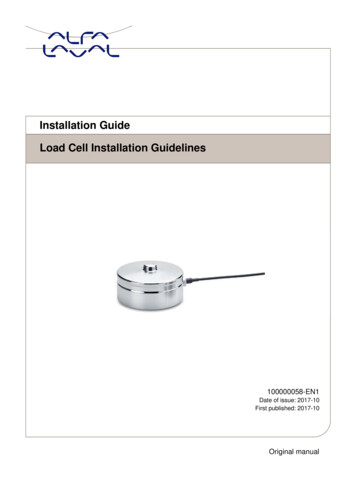
vInstallation GuideLoad Cell Installation Guidelines100000058-EN1Date of issue: 2017-10First published: 2017-10Original manual
Contents1) Introduction . 32) Electrical Installation . 33) Mechanical Installation – General Information . 54) Mechanical installation of compression load cells for tanks . 8General Installation of compression load cells . 8Installations for vessels with lugs/brackets . 11Installations requiring lift-off protection . 124.1 Gravimetric Level Measurement - Positioning of the load cells . 154.2 Recommendations - Process Connections . 165) Mechanical mounting of beam load cells . 175.1 General installation of beam load cells . 175.2 Installation of beam load cells for conveyer belts and belt scales . 186) Mechanical mounting of Alfa Laval single point load cells . 197) Calibration . 208) How to contact Alfa Laval Kolding A/S . 20Load Cell Installation Guide100000058-EN1Page 1
Page 2Load Cell Installation Guide100000058-EN1
1) IntroductionAn Alfa Laval load cell is a unique capacitive transducer that is used to measure weight or force.When the weight (force) is applied to the load cell, it causes a distance change inside the load cell,which a non-contacting capacitive sensor measures very accurately. This capacitive measurementresults in a digital value, which is proportional to the force applied to the load cell.The load cells may only be used for the weighing applications for which they were designed. Thedimensions of all mounting and structural components must be calculated to ensure sufficient overloadcapacity.Installation and repair work should only be carried out by qualified personnel.2) Electrical InstallationThe power needed for each weighing system is 24 VDC, min. 2A unless otherwise specified.Don't ever carry a load cell by the cable!For applications in hazardous ATEX (Ex) rated area, load cell modules and instrumentation must beinstalled outside the hazardous zone. Furthermore, only ATEX certified load cells, instrumentation andpower supply are allowed for use in ATEX applications.The load cells should be installed so that the load cell cable will not be cut or otherwise damagedduring installation or use.Always keep the open end of the load cell cable protected against humidity.If you want to extend the cable, we recommend that you buy a longer cable from Alfa Laval.Alternatively, you can use a male-female connector pair that is protected from moisture ingress.If welding is performed on the installation, remember to disconnect the load cells from theinstrumentation.Load Cell Installation Guide100000058-EN1Page 3
Please follow these instructions for mounting the BNC connector on the load cell cable (werecommend using the crimp tool from Weidmüller type HTG 58/59 or similar):1.2.3.4.5.6.7.The load cell cable is put through the metal tubeThe insulation is removed and the shield is folded out and backwardsThe Gold pin is crimped on the center wire (check tightness of crimp with a light pull)Load cell cable with gold pin is pushed into BNC connector until it is locked (a small “click”)The shield is folded around the neck of the BNC connectorThe metal tube is drawn over the shieldExcess shield is cut of and metal tube is crimped tightFor further information on electrical installation, please consult the documentation following theinstrumentation.Page 4Load Cell Installation Guide100000058-EN1
3) Mechanical Installation – General InformationThe mechanical installation of an Alfa Laval load cell is very simple and easy as sideload and overloadprotection devices are most often not necessary since the non-contacting capacitive measuringprinciple allows for high overloads and sideloads.When mounting the load cell, it is placed between the force introducing structure and the base, whichideally are two parallel surfaces.For highest accuracy, please ensure that the force is applied vertically on the loading surface (loadpoint) of the load cell. The force should not be applied to the load cell outside the loading surface (loadpoint).Load Cell Installation Guide100000058-EN1Page 5
Please notice that rigid process tubing will cause errors and should be considered when designing theinstallation:To prevent force shunts, all connections from the weighing system to the surrounding construction(pipes, cables, bellows) must be as flexible as possible.Page 6Load Cell Installation Guide100000058-EN1
Any component or part causing resistance to vertical movement of the load, the parts to be weighedand the load cells will induce accuracy errors.Determine if any vibration or influence on the weighing system is caused by other systems operatingclose by. If possible, do try to minimize the vibrations on the load cells in order to achieve the bestweighing performance.Load Cell Installation Guide100000058-EN1Page 7
4) Mechanical installation of compression load cells for tanksGeneral Installation of compression load cellsPreferably, the load cell is placed directly on an even and hard surface.In environments with rough or uneven surfaces it is recommended that the load cell is placed on abase plate to ensure a proper foundation.The following positioning of the load cells is recommended for vessels with 3 or 4 legs - always balancethe forces equally on the load cells if possible:For process installations with process tubing/piping, the process tubing/piping should have the highestpossible flexibility to vertical movements by having the longest possible free horizontal length.The error from the process piping is equal to the force that is required to deflect the piping 0.2 mm(equivalent to the deflection of the load cells at rated capacity). However, the stiffness of the processpiping may to a certain degree be calibrated out by changing the slope (calibration factor) of the output.Remember to tighten all process connections before calibration.We recommend flexible connections to optimize accuracy and the process piping should be balancedaround the vessel. Avoid rigid cabling to mixers and agitators. Where possible, agitators should bebalanced and positioned at the centre of the vessel.Page 8Load Cell Installation Guide100000058-EN1
When multiple pipes are connected to a weighing vessel, then the connections should preferably beflexible and made as symmetrical as possible.After mechanical installation, check if there is any contact between the tank and other structures as thisis the number one cause of inaccuracy in a weighing installation:Load Cell Installation Guide100000058-EN1Page 9
For installations where all the legs of the tank are supported by load cells, horizontal forces will onlycause minimal weighing errors as the load will be shifted from one load cell to another, but the sumof the load on the load cells will remain constant.Remember to allow some air around the loading point of the compression load cells to allow thestructure of the tank, silo or vessel to expand and contract during temperature changes (thermalexpansion) as shown below:Page 10Load Cell Installation Guide100000058-EN1
Installations for vessels with lugs/bracketsThis installation method is very similar to the installation with tank legs. Alfa Laval can provide thepositioning ring if required:Load Cell Installation Guide100000058-EN1Page 11
Installations requiring lift-off protectionIf the installation is placed outdoor subjected to wind loading, or seismic activity or indoor with a risk oftilting, a lift-off protection must be used.The lift-off protection can be used on one or both sides of each load cell depending on the size of the siloand the local conditions. Lift-off bolts must restrain the maximum upward movement.A clearance should be provided to prevent the bolts from mechanically interfering with the silo duringnormal use as this will cause weighing errors.Page 12Load Cell Installation Guide100000058-EN1
1-2mmTank legtOversized holeLift off protectionLoad cellbGroundwInstallations requiring lift-off protection (indoor)The following table is only to be used as a guideline for indoor installations(Dimensioning of the lift-off protection must be calculated individually for ad ExLoad Cell Installation Guide100000058-EN1Load cellNo. ofcapacitytank legs(ton)Top plate(t in 35020-50450Top 5Class 8.8M1265Class 8.8M16120Class 8.8M16120Class 8.8M20200Class 8.8M20200Class 8.8M24290Class 8.8M24290Class 8.8Page 13
Installations requiring lift-off protection (outdoor)The following table is only to be used as a guideline for outdoor installations (Dimensioning of the liftoff protection must be calculated individually for each installation!).If the height is greater ( ) than 2 times the diameter of the silo, special pre-cautions must be taken anddimensioning of the lift-off protection must be carefully calculated for the installation!W(mm)150150150150200200200200Page 14Load ExLoad cellNo. ofcapacitytank legs(ton)Top plate(t in 36020-50460Top 00Class 8.8M16120Class 8.8M24290Class 8.8M20200Class 8.8M30450Class 8.8M30450Class 8.8M42950Class 8.8M42950Class 8.8Load Cell Installation Guide100000058-EN1
4.1 Gravimetric Level Measurement - Positioning of the load cellsYou can achieve the highest accuracy by using load cells under all legs of the vessel. However, asimple and cost-effective solution for gravimetric level measurement is achieved by only using loadcells under some of the legs (supporting points).Using gravimetric level measurement, you can expect about 1-2% accuracy if the installation isperformed with a bit of care, and the vessel is mechanically stable.The following drawings show the positioning of the load cells for different no. of legs on the vesselwhen you don’t use load cells under all the legs:A further benefit of using load cells for level measurement is that you can always upgrade theaccuracy by installing load cells under all the legs.For installations where not all the legs of the vessel are supported by load cells, the process pipingshould have a high flexibility also to horizontal movements.Otherwise, the piping, especially if there are connections at the top of the tank, will be able to shift theload to or from the vessel leg(s) with the load cell(s) and thus cause weighing errors.One of the further advantages of using load cells for gravimetric level measurement is that the properoperation of the system may easily be confirmed by applying a known load on the system.For other advantages of using load cells for gravimetric level measurement, please visit our homepage(http://www.Alfa Laval.com/weighing-solutions/).Load Cell Installation Guide100000058-EN1Page 15
4.2 Recommendations - Process ConnectionsThis document describes our recommendations regarding connections of pipes and tubes for processweighing applications.Ideally, the tank should be able to move freely in the vertical direction so the process connections shouldhave the highest possible vertical flexibility.Therefore, flexible connections mounted horizontally to allow for vertical movements should be considered.For sanitary applications or where it is not feasible to use flexible connections, the following free horizontallength of the piping is recommended:Diameter/wall thicknessPiping up to max. 16 mm/1 mmPiping up to max. 25 mm/1-1,5mmPiping up to max. 50 mm/2 mmPiping diameter 50 mmRecommendation 500 500 mm (or 400 600 mm etc.) freehorizontal length with at least one 90 degreehorizontal bend 800 800 mm (or 400 1200 mm etc.) freehorizontal length with at least one 90 degreehorizontal bend 1000 1000 1000 mm (or 600 1200 1200mm etc.) free horizontal length with at least two 90degree horizontal bendsThe actual situation should be treated individuallyIt is always preferable to have the bends in three dimensions.When the above mentioned rules have been followed, the influence from the process connections can beremoved by a calibration.Theoretically, if a load cell has no deflection at all, the influence from process connections during loading ofthe weighing system will be zero. So the smaller the deflection of the load cell is, the smaller is the influencefrom process connections.As a general rule, the Alfa Laval capacitive load cells only have a deflection of about 0,10 mm at fullcapacity, contrary to other types of load cells which typically has a deflection of more than 0,20 mm at fullcapacity.When using load cells under all supporting points, horizontal forces will be compensated because thehorizontal forces will only shift the load between the load cells.We will be happy to give advice on process connections if drawings (2D/3D) are provided. The informationwill be treated as confidential.Page 16Load Cell Installation Guide100000058-EN1
5) Mechanical mounting of beam load cells5.1 General installation of beam load cellsWe recommend using a flexible mounting part when installing beam load cells in mechanical structuresthat are not perfectly aligned. This prevents torque on the load cells caused by the mechanicalmounting of the load cells when the mounting bolts are tightened:Load Cell Installation Guide100000058-EN1Page 17
5.2 Installation of beam load cells for conveyer belts and belt scalesWhen installing beam load cells for conveyers and belt scales, it is important that the load cells areinstalled in the direction along the movement of the product or items to be weighed:CORRECTNOT CORRECT!Page 18Load Cell Installation Guide100000058-EN1
6) Mechanical mounting of Alfa Laval single point load cellsRemember to use the four (4) cylinders supplied with the single point load cells.These cylinders will make sure that there is only contact with the load at the correct load points of theload cell. Also, the cylinders eliminate the need to specify the torque used for the mounting bolts.Load Cell Installation Guide100000058-EN1Page 19
7) CalibrationThe Alfa Laval digital load cells are supplied pre-calibrated i.e. the load cells transmit the weight(force) directly in grams, kilograms or tons.However, if the measurement is interfered by mechanical factors like heavy process piping, gearsetc. then it can be necessary to perform a calibration of the complete system.For more specific calibration guideline, please follow the calibration instruction for the suppliedinstrumentation.8) How to contact Alfa Laval Kolding A/SFor further information please feel free to contact:Alfa Laval Kolding A/S31, Albuen - DK 6000 Kolding - DenmarkRegistration number: 30938011Tel switchboard: 45 79 32 22 00 - Fax switchboard: 45 79 32 25 80www.toftejorg.com, www.alfalaval.dk - info.dk@alfalaval.comContact details for all countries are continually updated on our websites.Page 20Load Cell Installation Guide100000058-EN1
How to contact Alfa LavalContact details for all countries arecontinually updated on our website.Please visit www.alfalaval.com to access the information directly. Alfa Laval Corporate ABThis document and its contents is owned by Alfa Laval Corporate AB and protected by laws governing intellectual property and thereto related rights. It is the responsibility of the user of thisdocument to comply with all applicable intellectual property laws. Without limiting any rights related to this document, no part of this document may be copied, reproduced or transmitted in anyform or by any means (electronic, mechanical, photocopying, recording, or otherwise), or for any purpose, without the expressed permission of Alfa Laval Corporate AB. Alfa Laval Corporate ABwill enforce its rights related to this document to the fullest extent of the law, including the seeking of criminal prosecution.
Load Cell Installation Guide Page 3 100000058-EN1 1) Introduction An Alfa Laval load cell is a unique capacitive transducer that is used to measure weight or force. When the weight (force) is applied to the load cell, it causes a distance change inside the load cell, which a non-contacting capacitive sensor measures very accurately.