Transcription
A REVIEW OF API MPMS CHAPTER 14.3/AGA REPORT NO. 3 PART 2Edgar B. Bowles, Jr.Jacob L. ThorsonSouthwest Research Institute6220 Culebra RoadSan Antonio, TX 78238 USAIntroductionThis paper describes the current contents of the United States (U.S.) orifice flow metering standard American PetroleumInstitute (API) Manual of Petroleum Measurement Standards (MPMS) Chapter 14.3, “Orifice Metering of Natural Gas andOther Related Hydrocarbon Fluids,” Part 2, “Specification and Installation Requirements.”[1] This document is also known asAmerican Gas Association Report No. 3, Part 2.[2] As of the writing of this paper (i.e., May 2017), this standard was in itsfifth edition and was last revised in March 2016.API MPMS, Chapter 14.3, includes four parts: Part 1:Part 2:Part 3:Part 4:General Equations and Uncertainty GuidelinesSpecification and Installation RequirementsNatural Gas ApplicationsBackground, Development Implementation ProcedureThe focus of this paper is Part 2 of the standard.As a brief history of the development of API MPMS, Chapter 14.3, Part 2, research on orifice flow meters began in the U.S.around 1904. Thomas Weymouth published an ASME paper in 1912 describing the results of a series of flow experimentsdating to 1904 that he had performed on a flange tap orifice meter. Orifice meter research by what was known at the time asthe National Bureau of Standards (NBS) (now known as the National Institute of Standards and Technology (NIST)) andothers continued through the late 1920s. The first U.S. metering standard was produced by the American Gas Association in1930 AGA Report No. 1 (which later evolved into API MPMS, Chapter 14.3 or AGA Report No. 3) for orifice flow meters.This followed the publication of a preliminary report published in 1927 and revised in 1929.AGA Report No. 2 was published in 1935. Key enhancements to Report No. 2 were improved orifice coefficients based on alarger experimental dataset and the addition of supercompressibility factors for natural gas.AGA Report No. 3 was first published in 1955 and incorporated an even larger experimental dataset than did Report No. 2.Report No. 3 was first revised in 1969, and subsequently revised again in 1985, 1992, and 2000. The API first adoptedAGA Report No. 3 as a standard in 1975, and the American National Standards Institute (ANSI) first recognized thedocument as a national standard in 1977.Annex A describes much of the critical research related to the development of Part 2 of API MPMS, Chapter 14.3 and citesover 200 separate research studies performed on orifice flow meters between 1922 and 1999.
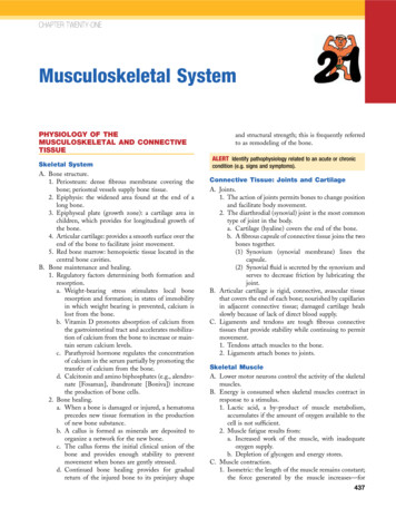
Scope of the StandardThe scope of API MPMS, Chapter 14.3, Part 2 currently includes the following:1.2.3.4.5.6. Construction and Installation RequirementsNormative ReferencesTerms, Definitions, and SymbolsOrifice Plate SpecificationsMeter Tube SpecificationsInstallation RequirementsAnnexesA Research Projects and Tests Conducted Between 1922 and 1999B Orifice Meter Inspection GuidelinesC Specific Installation Calibration TestD Flow Conditioner Performance TestE Maximum Allowable Orifice Plate Differential PressureThe following sections describe the principal contents of API MPMS, Chapter 14.3, Part 2. Note that all section, figure, andtable numbers are from the fifth edition of API MPMS, Chapter 14.3, Part 2. These numbers are not the same as in theprevious versions of this standard.Construction and Installation Requirements (Section 1.2)This section notes that Part 2 includes the mechanical tolerances for the flow meter assembly required to ensure accurate flowmeasurement and the potential for measurement error associated with not maintaining the meter within the specifiedtolerances. This section also includes a “grandfather” clause, which essentially gives the flow meter operator/owner thediscretion to decide whether or not to upgrade a given flow meter to the most current specifications whenever a new revisionto Part 2 is published. If the operator chooses not to upgrade the meter to the latest specifications, additional flowmeasurement bias errors may result possibly because of inadequate flow conditioning and upstream straight pipe length.This section also provides cautionary guidance on diameter ratio (i.e., the ratio of the orifice bore diameter to the meter tubediameter, βr) limits, and maintenance and upkeep of the flow meter to help ensure accurate flow measurement. (Diameterratio is also sometimes referred to as beta ratio.) Specifically, this section states that the standard is based on beta ratios of0.10 to 0.75, with the best results between 0.2 and 0.6 with orifice bore diameters greater than 0.45-inches. These are nothard limits, but diameter ratios and bore diameters outside of these limits may require special considerations.Normative References (Section 2)This section would list other standards that are necessary for the application of this standard, but currently none are listed.Terms, Definitions, and Symbols (Section 3)This section provides definitions for all of the parameters used in the equations, figures, and tables referenced in Part 2. Thissection also provides definitions for the key terms referenced in Part 2, such as orifice plate, meter tube, diameter ratio, andflow conditioner, among others.Orifice Plate Specifications (Section 4)This section provides dimensional tolerances for the key components of an orifice flow meter assembly. This includestolerances for the following: Orifice plate facesOrifice plate bore edgesOrifice plate bore diameter (dm) and roundness (dr)Orifice plate bore thickness (e)Orifice plate thickness (E)Orifice plate bevel angle (θ)
Figure 1 shows the symbols for the orifice plate dimensions that were defined in Section 3. This figure is similar to the figureincluded in subsection 4.1 of the standard. These symbols and nomenclature are used throughout the rest of the report.Figure 1. Symbols for Orifice Plate DimensionsThe flatness of the orifice plate is a critical parameter that influences the accuracy of the flow measurement. Allowabletolerances for the plate flatness are included in subsection 4.2, which describes the requirements for orifice plate faces. Thisalso includes restrictions and recommendations on the plate roughness, flatness, cleanliness, and other factors. One examplemethod of measuring this flatness is shown in Figure 2, which is similar to Figure 2a of Part 2.Figure 2. Orifice Plate Departure from Flatness(Measured at the edge of orifice bore and within inside pipe diameter)Subsection 4.3 describes methods of inspecting the edge of the orifice bore, which can critically affect measurementaccuracy. The roundness of the orifice bore is described and defined in subsection 4.4, and Table 1 includes tolerances forthe orifice bore roundness for different ranges of bore diameters. Subsection 4.4 also describes the methodology ofaccurately measuring the orifice plate bore diameter.The next subsection describes the thickness of the orifice plate bore as defined in Section 3. Subsection 4.5 describes thegeometry of the orifice plate bore and applies special considerations to this portion of the orifice plate. The standard thenprovides equations to determine the maximum and minimum orifice plate bore diameter thickness. The upper and lowerlimits on the bore thickness depend on both the bore diameter and the pipe diameter. The minimum bore thickness is plottedin Figure 3. The maximum bore thickness is plotted for two different inside pipe diameters in Figure 4. This subsection alsoestablishes the requirement for a bevel (described later) when the orifice plate bore thickness, e, is smaller than the orificeplate thickness, E.
Figure 3. Relationship between Minimum Bore Thickness and Bore DiameterFigure 4. Relationship between Maximum Bore Thickness and Beta Ratio for Two Pipe SizesNext, subsection 4.6 describes the thickness of the orifice plate itself when using Type 304 or 316 stainless steel orifice platesand operating temperatures less than 150 F. The minimum, maximum, and recommended values for orifice plate thickness,E, and allowable range of differential pressure across the orifice plate are provided in Table 3. Note that the maximumallowable differential pressure is limited to 1,000 inches of water column, which is the limit of the coefficient of dischargedatabase. The maximum allowable differential pressure for the recommended orifice plate thicknesses shown in Table 3 arefor a maximum operating temperature of 150ºF. Additional guidance regarding allowable differential pressure across theorifice plate is provided in Annex E of Part 2. An equation is provided in subsection 4.6.2 that allows the reader to estimatethe permanent pressure loss across an orifice plate as a function of beta ratio. This equation is plotted in Figure 5.Figure 5. Relationship between Beta Ratio and Permanent Pressure LossIf required, the orifice plate bevel is described in subsection 4.7. The allowable tolerance for the orifice plate bevel angle, θ,(i.e., the angle between the bevel and the downstream face of the orifice plate) is 45º 15º. If a bevel is required, itsminimum dimension, E minus e, measured along the axis of the bore, shall not be less than 0.0625 inch.
Meter Tube Specifications (Section 5)The meter tube is defined as the straight length of pipe upstream of the orifice plate (of the same diameter), including theflow straightener/conditioner, if used; the orifice plate holder; and the similar downstream pipe beyond the orifice plate. Theupstream section of the meter tube is defined as the length of straight pipe extending from the upstream face of the orificeplate to the nearest upstream change in the cross-sectional area (not including flange fittings allowed by this standard) orchange in axis of the pipe centerline. Guidance is given regarding avoiding upstream and downstream flow disturbances inthe meter tube, especially regarding the location of the connections and the gaskets relative to the orifice plate.In subsection 5.1.1, allowable tolerances are provided for the meter tube surface roughness. Guidance is also provided onwhere to measure surface roughness along the meter tube. Meter tube surfaces that are too hydrodynamically “smooth” or“rough” will result in a flow measurement bias error. Allowable tolerances for meter tube surface irregularities, such asgrooves, gouges, scoring, or ridges resulting from seams, welding distortion, etc. are also provided. It also requires that themeter tube be kept clean and free from accumulation of dirt, ice, grit, grease, oil, free liquid, and other extraneous material. Ifthese restrictions are not followed, flow measurement bias errors may result.Procedures are provided for measuring the meter tube diameter, Dm, in subsection 5.1.2. This includes guidance on howmany measurements should be taken, where they should be taken, and where the user should take check measurements forverification. Figure 6 shows an example application of the temperature correction that is provided in this subsection asapplied to a nominal 16-inch, schedule XS, carbon steel meter tube.Figure 6. Predicted Inner Diameter of a 16-inch, Schedule XS, Carbon Steel Pipe as Temperature VariesSubsection 5.1.3 provides tolerances for both meter tube diameter and roundness - both upstream and downstream of theorifice plate. Table 1 and Table 2Error! Reference source not found. are taken from Tables 4 and 5 of the standard,respectively. They both provide examples of the meter tube internal diameter roundness tolerances. Abrupt changes to theinside meter tube surface, such as shoulders, offsets, ridges, welding seams, etc., are generally disallowed.Position1-inch Upstream PlateWithin one Dm% Deviation from Mean DmMeter Tube Internal Diameter Measurements (in)ABCDMean, 2.0655N/A0.024% 0.092% 0.116% 0.193%N/ATable 1. Example Meter Tube Internal Diameter Roundness Tolerances within the First Mean Tube DiameterUpstream of the Orifice PlatePosition1-inch Upstream PlateWithin one DmUpstream Check MeasurementMeter Tube Internal Diameter Measurements (in)ABCDMean, 2.0655N/A2.06212.06202.06132.0601N/ATable 2. Example Meter Tube Internal Diameter Roundness Tolerances All Upstream Meter Tube IndividualInternal Diameter Measurements
Recommendations are included regarding orifice plate gasket or sealing device tolerances in subsection 5.1.4. These includethe specific prohibition of protrusions into the pipe bore by gaskets or other sealing devices. This subsection also discussesthe recess resulting from a gasket or sealing device and describes the effect of this recess on uncertainty for various recessgeometries.Subsections 5.2, 5.3, and 5.4 describe the various orifice configurations and pressure tap locations, respectively. Orificeflanges and orifice fittings, along with the associated inspection considerations, are discussed. Generally, it is recommendedthat these fittings adhere to the tolerances provided earlier in the standard. Guidance is provided on the proper location andconfiguration (e.g., geometry) of pressure taps adjacent to the orifice plate. For instance, Figure 7 shows the allowablevariations in pressure tap hole location for flange taps and is similar to the plot shown in Figure 3 in the standard. Subsection5.4 also provides equations and guidance for avoiding resonance in the pressure sensing lines, which can cause measurementissues and other issues.Figure 7. Allowable Variations in Pressure Tap Hole LocationSubsection 5.5 extensively discusses flow conditioners and their application to orifice flow measurement. A flow conditioneris a device placed upstream of the orifice plate that attempts to correct or eliminate flow field distortions created by theupstream piping configuration. Flow conditioners fall in one of two categories flow straighteners and isolating
AGA Report No. 3 as a standard in 1975, and the American National Standards Institute (ANSI) first recognized the document as a national standard in 1977. Annex A describes much of the critical research related to the development of Part 2 of API MPMS, Chapter 14.3 and cites over 200 separate research studies performed on orifice flow meters between 1922 and 1999. Scope of the Standard The .
![API Ballot: [Ballot ID] – API 510 & API 570, Deferrals, Rev05](/img/5/api510andapi570deferralsrev5.jpg)