Transcription
22 The Flame Ionization DetectorGeneral InformationFID pneumaticsSpecial considerationsConditions that prevent the detectorfrom operatingDetector shutdownJetsAutomatic reignition—Lit offsetProcedure: Changing the auto-reignite setpointMaintaining a Flame IonizationDetectorCorrecting FID hardware problemsReplacing or cleaning the jetProcedure: Removing and inspecting the jetProcedure: Cleaning the jetProcedure: Installing the jetOperating the FIDCleaning the collectorProcedure: Removing the collectorProcedure: Cleaning the collectorProcedure: Reassembling thedetectorProcedure: Replacing the FID ignitionwireColumns and TrapsThe Nickel Catalyst TubeGas pressuresGas flowsOperating with EPCProcedure: Using the FIDTemperatureElectrometerData ratesProcedure: Using fast peaksRepacking the catalystCheckout Conditions andChromatogramFID checkout conditionsTypical FID checkout chromatogram514Return to Contents
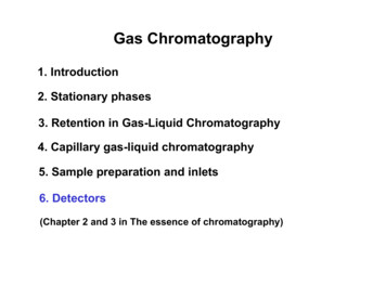
The Flame Ionization DetectorGeneral InformationThe flame ionization detector passes sample and carrier gas from the columnthrough a hydrogen-air flame. The hydrogen-air flame alone creates few ions,but when an organic compound is burned there is an increase in ions produced.A polarizing voltage attracts these ions to a collector located near the flame. Thecurrent produced is proportional to the amount of sample being burned. Thiscurrent is sensed by an electrometer, converted to digital form, and sent to anoutput device.FID pneumaticsFigure 73 illustrates the pneumatics design for the rsAir inPSPressurecontrol loopsH2 inPSMakeup inPSRestrictorsFigure 73 Schematic of a flame ionization detector515Return to Contents
General InformationThe Flame Ionization DetectorSpecial considerationsSpecial considerationsConditions that prevent the detector from operating Temperature set below 150 CAir or hydrogen flow set at Off or set at 0.0Ignition failureDetector shutdownIf a critical detector gas is shut down due to a pneumatics or ignition failure,your detector shuts down. This turns off everything except the detectortemperature and makeup gas flow.516Return to Contents
General InformationThe Flame Ionization DetectorJetsJetsThere are two types of FID available. The capillary optimized FID is only used withcapillary columns, and the adaptable FID fits packed columns and can be adapted tofit capillary columns.Capillary optimized fittingAdaptable fittingTable 59 Jets for the Capillary-Optimized FIDJet typePart no.Jet tip idCapillaryG1531-805600.29 mm (0.011-inch)High-temperature(use with simulated distillation)G1531-806200.47 mm (0.018-inch)Table 60 Jets for the Adaptable FIDJet typePart no.Jet tip idCapillary19244-805600.29 mm (0.011-inch)Packed18710-201190.47 mm (0.018-inch)Packed wide-bore(use with high-bleed (use with simulated distillation)19244-806200.47 mm (0.018-inch)Your detector is shipped with a capillary column jet. If you are doing simulateddistillation or high-temperature runs, you must change the jet. Instructionsappear in ”Replacing or cleaning the jet”.517Return to Contents
General InformationThe Flame Ionization DetectorAutomatic reignition—Lit offsetAutomatic reignition—Lit offsetLit offset is the expected difference between the FID output with the flamelit and the output with the flame off. If the output falls below this value, the FIDwill attempt to reignite twice. If the output does not increase by at least thisvalue, the detector shuts down all functions except temperature and makeup gasflow.The default setting for Lit offset is 2.0 picoamps. This is a good workingvalue for all but very clean gases and systems. You may want to change thissetpoint if: Your detector is attempting to reignite when the flame is still on, thusproducing a shutdown.Your detector is not trying to reignite when the flame is out.Procedure: Changing the auto-reignite setpoint1. [Press [Config][Front Det] or [Config][Back Det].Lit offset2. Scroll to Lit offset and enter a number.The default is 2.0 pA.Enter 0 to disable the automatic reignite function.The setpoint range is 0 to 99.9 pA.518Return to Contents
General InformationThe Flame Ionization DetectorElectrometerElectrometerThe Configure Detector control table contains an On/Off setpoint for theElectrometer. You do not need to turn the electrometer on and off whenoperating your FID. The only time you need to turn off the electrometer is whencleaning the detector.CautionDo not turn off the electrometer during a run. It will cancel detector Output.Data ratesAnalog output for the FID can be presented at either of two speeds. The fasterspeed allows minimum peak widths of 0.004 minutes, while the standard speedallows peak widths of 0.01 minutes.Procedure: Using fast peaksIf you are using the fast peaks feature, your integrator must be fast enough to processthe data coming from the GC. It is recommended that your integrator bandwidth be atleast 15 Hz. To use fast peaks:1. Press [Config][Signal 1] or [Config][Signal 2]2. Press [On]Digital output to the ChemStation is available at eleven speeds ranging from0.1 Hz to 200 Hz, capable of handling peaks from 0.001 to 2 minutes wide. Consult”Signal Handling”.The fast peaks feature does not apply to digital output.519Return to Contents
Operating the FIDThe Flame Ionization DetectorOperating the FIDUse the information in Table 61 when selecting temperatures and flows. Choosea minimum source pressure from Figure 74.Table 61 Recommended Temperature and Flow Rates—FIDGasFlow range(mL/min)Suggested flow(mL/min)Carrier gas(hydrogen, helium, nitrogen)Packed columnsCapillary columns10 to 601 to 5Detector gasesHydrogen24 to 60*40Air200 to 600*450Column plus capillary makeupRecommended: nitrogenAlternate: helium10 to 6050Detector temperature 150 C, flame will not light, prevents condensation damageDetector temperature should be approximately 20 C greater than highest oven ramptemperature depending on the column type.Lit offset [Config][Front Det] or [Config][Back Det]If the detector output (when the flame is on) minus the detector output (when the flameis off) falls below this value, the FID attempts to reignite twice. If output does notincrease by at least this value, the detector shuts down.2.0 pA is the recommended setting.0.0 pA disables the autoreignite function.*The hydrogen-to-air ratio should be between 8% and 12% to keep the flame lit.520Return to Contents
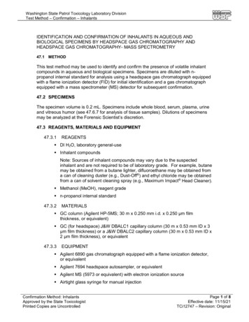
Operating the FIDThe Flame Ionization DetectorGas pressuresGas pressuresChoose a flow, find a pressure. Set source pressure 10 psi (70 kPa) n3020100Pressure 70482.660413.770482.6700600500FLOW(mL/min) 400Air3002001000Pressure (psig)kPa1069.020137.930206.840275.850344.7Figure 74 Typical pressure/flow relationships for FID gases(at 25 C and 1 atmosphere of pressure)521Return to Contents
Operating the FIDThe Flame Ionization DetectorOperating with EPCOperating with EPCPress [Front Det] or [Back Det].Temperature, CHydrogen flow, mL/minAIr flow, mL/minTurn off for packed columns.For capillary columns, seemakeup gas flow mode below.Makeup gas typePress [On] to ignite flameDisplays output value.Makeup gas flow mode:If column dimensions are specified, the control table will also includeone of these:To change makeup mode, scroll to Mode: and press [Mode/Type].Make a selection and enter the appropriate flow values.To view makeup gas or change Lit offset, press[Config][Front Det] or [Config][Back Det]:To change makeup gas type,press [Mode/Type]:It is not necessary to turn the electrometeron or off unless you are performing amaintenance procedure.Select the appropriate gas.Figure 75 FID control table522Return to Contents
Operating the FIDThe Flame Ionization DetectorOperating with EPCProcedure: Using the FIDVerify that all detector gases are connected, a column is installed, the correct jetis installed, and the system is free of leaks. Check the oven temperature, inlettemperature, and column flow. Use Figure 75 as a guide when operating the FID.WARNINGVerify that a column is installed or the FID column fitting is plugged beforeturning on the air or hydrogen. An explosion may occur if air and hydrogen areallowed to leak into the oven.1. Press [Front Det] or [Back Det] to open the FID control table.2. Set the detector temperature. The temperature must be greater than 150 Cfor the flame to light.3. Change the hydrogen flow rate, if desired, and press [Off].4. Change the air flow rate, if desired, and press [Off].5. If you are using packed columns, turn off the makeup gas and proceed to Step 7.Short-cutprocedure:(assumescorrect setpointsare stored)1.Open detectorcontrol table.2.Turn temperature On.3. Turn makeupgas On, ifneeded.4.Press[Det Control].5.Press [On].6. If you are using capillary columns:a. Verify that makeup gas type is the same as that plumbed to yourinstrument (next to Mkup line of control table). Change the gas type, ifnecessary.b. If your capillary column is defined and connected to an EPC inlet, choose anew flow mode, if desired, and set the makeup gas flow or combined flow.c. If your capillary column is not defined or connected to a nonEPC inlet, entera makeup gas flow. Only constant flow is available in this case.7. Scroll to Flame and press [On]. This turns on the air and hydrogen andinitiates the ignition sequence. The signal typically increases to 5 to 20 pAafter ignition. Verify that the flame is lit by holding a cold, shiny surface, suchas a mirror or chrome-plated wrench, over the collector exit. Steadycondensation indicates that the flame is lit.523Return to Contents
Checkout Conditions and ChromatogramThe Flame Ionization DetectorFID checkout conditionsCheckout Conditions and ChromatogramThis section contains a typical examples of a test sample chromatogram. It maybe used as a general guide to instrument performance.Note that injection volumes listed with operating conditions do not necessarilyindicate total absolute volume injected. Volume given is simply the graduation(plunger position) read from a standard 10 µL syringe. For a heated inlet, actualsample volume injected will also include an additional 0.4-0.7 µL, the volume ofsample volatilized from inside the syringe needle. For the dedicated, on-columninlet (unheated), the syringe plunger position more accurately reflects the trueinjected volume.Also note that the following procedure and results are intended only to provideevidence of a properly functioning inlet and/or detector system; they are notnecessarily suitable to test a given system against its specification limits.FID checkout conditionsColumn and sampleTypeHP-5 30m x 0.32mm x 0.25µm PN 19091J-413SampleFID Checkout 18710-60170Injection volume1 µLInletTemperature250 C Purged/Packed or Split/SplitlessOven Track Cool On-Column40 C PTV (see below)Inlet pressure25 psi (Constant pressure, helium)Split/SplitlessModeSplitlessPurge flow60 mL/minPurge time0.75 min524Return to Contents
Checkout Conditions and ChromatogramThe Flame Ionization DetectorFID checkout conditionsInlet, continuedPTVModeSplitlessInlet temperature40 CInitial time0.1 minRate 1720 C/minFinal temp 1350 CFinal time 12 minRate 2100 C/minFinal temp 2250 CFinal time 20 minInlet pressure25 psi (Constant pressure)Purge time0.75 minPurge flow60 mL/minDetectorTemperature300 CH2 flow30 mL/minAir flow400 mL/minMakeup flow (N2)25 mL/minOffsetShould be 20 pAOvenInitial temp40 CInitial time0 minRate 125 C/minFinal temp90 CFinal time0 minRate 215 C/minFinal temp170 CFinal time2 min525Return to Contents
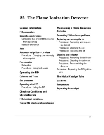
Checkout Conditions and ChromatogramThe Flame Ionization DetectorTypical FID checkout chromatogramTypical FID checkout chromatogram6.0416.9071.0677.766Your retention times will differ, but the peaks should be symmetric as in thisexample.526Return to Contents
Maintaining a Flame Ionization DetectorThe Flame Ionization DetectorMaintaining a Flame Ionization DetectorWARNINGFlame ionization detectors use hydrogen gas as fuel. If hydrogen flow is on andno column is connected to the detector inlet fitting, hydrogen gas can flow intothe oven and create an explosion hazard. Detector fittings must have either acolumn or a cap connected at all times.Detector top assemblyUpper collector insulationCopper washerIgnition wire assemblyCollectorCollector bottom assemblyLower collector insulationCollector housingElectrometerBase spanner nutCable connector toPC boardThermal strapJetHeater/sensorassemblyDetector weldmentInsulationColumn connection527Return to Contents
Maintaining a Flame Ionization DetectorThe Flame Ionization DetectorCorrecting FID hardware problemsCorrecting FID hardware problemsThe flame goes out or will not light WARNINGCheck the column flow rate. It may be too high. Decrease the flow rate orpressure. Switch to a more restrictive column (longer or with a smaller id).If you must use a large id column, turn off the carrier flow long enough toallow the FID to light. Check for partially or completely plugged jet.Check that the right type of jet is installed for the column you are using. Jettypes are listed on page 517.Injecting large volumes of aromatic solvent can cause the flame to go out.Switch to a nonaromatic solvent.The lit offset value may be too low or too high. Adjust the value.Flame ionization detectors use hydrogen gas as fuel. If hydrogen flow is on andno column is connected to the detector inlet fitting, hydrogen gas can flow intothe oven and create an explosion hazard. Detector fittings must have either acolumn or a cap connected at all times.Replacing or cleaning the jetJets require periodic cleaning or replacement. Even with normal use, depositsdevelop in the jet (usually white silica from column bleed or black, carbonaceoussoot). These deposits reduce sensitivity and cause chromatographic noise andspikes. Although you can clean the jet, it is usually more practical to replace dirtyjets with new ones. If you do clean the jet, be very careful not to damage it.You may also need to change the jet when you change columns or analyses. Forexample, packed columns use different jets than capillary columns. You mustinstall the proper jet before changing the column.To change a jet, you must first remove the FID collector assembly. The procedure isdivided into three parts: removing and inspecting the jet, cleaning the jet(optional), and installing the jet.528Return to Contents
Maintaining a Flame Ionization DetectorThe Flame Ionization DetectorReplacing or cleaning the jetProcedure: Removing and inspecting the jetMaterials needed: Gloves to protect hands if detector is hotT-20 Torx screwdriver1/4-inch nut driverForceps (or tweezers)1. Complete the following preliminary steps: Cool the detector to room temperature. When the detector is cool, turn it off and turn off the gases at the GCkeyboard. Turn off the electrometer; press [Config] [Front Det] or [Config] [BackDet] to access the control table. Cool the inlet and then turn off the inlet gas. Cool the oven, remove the column, and plug the column connection. See”Columns and Traps” . Open the GC detector cover to access the FID.529Return to Contents
Maintaining a Flame Ionization DetectorThe Flame Ionization DetectorReplacing or cleaning the jet2. Put the gloves on if the detector is hot. Remove the three screws holding thecollector bottom assembly in place. Lift off the assembly. The insulator canremain in the collector bottom.GC detector coverCollector bottomassemblyLocation of jet in detector3. Using the nut driver, loosen the jet, and pull it straight out. You may need touse the forceps to grasp the jet.Location of jetElectrometer spring4. Inspect the jet sealing surface for scratches. You should see a ring aroundthe sealing surface; any other scratches, however, are unacceptable.Sealing surface530Return to Contents
Maintaining a Flame Ionization DetectorThe Flame Ionization DetectorReplacing or cleaning the jet5. Inspect the jet tube to make sure it is not bent or crimped. Inspect the jet forcontamination or pieces of broken column by holding it up to a light andlooking through it. If no contamination is present, the tube will be clear.Bent tube531Return to Contents
Maintaining a Flame Ionization DetectorThe Flame Ionization DetectorReplacing or cleaning the jetProcedure: Cleaning the jetIt is often more convenient to replace dirty jets with new ones than to clean them,especially jets that have been badly contaminated.If you choose to clean a jet, be careful when using a cleaning wire. Be sure notto scratch the jet internally, because doing so will ruin it. You may want to skipcleaning the jet with a wire and use the aqueous bath only.Materials needed: 1.Small ultrasonic cleaning bathAqueous detergentGC-grade methanol in a Teflon wash bottleFlame detector cleaning kit (part no. 9301-0985)Dry, filtered, compressed air or nitrogenForceps or tweezersRun a cleaning wire through the top of the jet. Run it back and forth a fewtimes until it moves smoothly. Be careful not to scratch the jet.2. Aqueous cleaning procedure:a. Fill the ultrasonic cleaning bath with aqueous detergent and place the jetin the bath. Sonicate for 5 minutes.b. Use a jet reamer to clean the inside of the jet.c. Sonicate again for 5 minutes.From this point on, handle the parts only with forceps (or tweezers)!d. Remove the jet from the bath and rinse it thoroughly with hot tap waterand then with a small amount of methanol.e. Blow the jet dry with a burst of compressed air or nitrogen and thenplace the jet on a paper towel to air dry.532Return to Contents
Maintaining a Flame Ionization DetectorThe Flame Ionization DetectorReplacing or cleaning the jetProcedure: Installing the jetCautionDo not over-tighten the jet! Over-tightening may permanently deform anddamage the jet, the detector base, or both.CautionHandle the clean or new jet only with forceps!Materials needed: Gloves to protect hands if detector is hot Forceps 1/4-inch hex driver T-20 Torx screwdriverSee page 517 for tables of jet types.1. Insert the jet and tighten with the hex driver until it is snug.533Return to Contents
Maintaining a Flame Ionization DetectorThe Flame Ionization DetectorReplacing or cleaning the jet2. Replace the collector assembly. Tighten the three screws securing thecollector assembly.Collector bottomassembly3. Reattach the column to the detector. You can now restore normal operatingconditions.534Return to Contents
Maintaining a Flame Ionization DetectorThe Flame Ionization DetectorCleaning the collectorCleaning the collectorThe collector requires occasional cleaning to remove deposits (usually whitesilica from column bleed, or black, carbonaceous soot). Deposits reducesensitivity and cause chromatographic noise and spikes.The cleaning procedure presented here suggests you use an ultrasonic bath toclean the collector and other parts of the detector. However, if your collector isnot too dirty, it may be sufficient to scrub it with a nylon brush and then use aburst of compressed air or nitrogen to blow stray particles away.This procedure is divided into three steps: removing the collector, cleaning thecollector, and reassembling the detector.535Return to Contents
Maintaining a Flame Ionization DetectorThe Flame Ionization DetectorCleaning the collectorProcedure: Removing the collectorMaterials needed: 1.T-20 Torx screwdriver1/4-inch nut driverForceps or tweezersGloves if the detector is hotComplete the following preliminary steps: Cool the detector to room temperature. When the detector is cool, turn off the temperature zone and the gasesat the GC keyboard. Turn off the electrometer; the electrometer control is in the Config Dettable. Press [Config] [Front Det] or [Config] [Back Det] to access thecontrol table. Open the GC detector cover to access the FID.2. Put on the gloves if the detector is hot. Loosen the knurled brass nut. Lift thetop assembly straight up. The upper Teflon insulator might stick to thebottom of the assembly. Remove the insulator.Detector topassemblyKnurledbrass nut536Return to Contents
Maintaining a Flame Ionization DetectorThe Flame Ionization DetectorCleaning the collector3. Lift out the collector. The upper insulator may be attached to the collector.You may need to use the tweezers to grasp the collector.Upper Teflon insulatorCollector4. Remove the three screws that hold the collector bottom assembly in place.Lift off the assembly. Remove the lower insulator from the bottom assembly.You may need to use the forceps to grab it.Collector bottomassembly with insulationinside (not visible in figure)537Return to Contents
Maintaining a Flame Ionization DetectorThe Flame Ionization DetectorCleaning the collectorProcedure: Cleaning the collectorMaterials needed: Small ultrasonic cleaning bath Aqueous detergent GC-grade methanol in a Teflon wash bottle Flame detector cleaning kit (part no. 9301-0985) Dry, filtered, compressed air or nitrogen Forceps or tweezersCleaning procedure:1. Fill the ultrasonic cleaning bath with aqueous detergent, and place the twoinsulators and the collector in the bath. Sonicate for 5 minutes.2. Use the nylon brushes to clean each piece.3. Sonicate again for 5 minutes.From this point on, handle the parts only with forceps or tweezers!4. Remove the pieces from the bath and rinse them thoroughly with hot tapwater and then with a small amount of methanol.5. Place the pieces on a paper towel to air dry.538Return to Contents
Maintaining a Flame Ionization DetectorThe Flame Ionization DetectorCleaning the collectorProcedure: Reassembling the detectorCautionHandle the clean collector and insulators only with forceps (or tweezers)!Materials needed: Forceps or tweezers T-20 Torx screwdriver1. Insert the lower insulator into the lower collector assembly. Install the lowercollector assembly and tighten the three screws.2. Replace the collector and install the upper Teflon insulator.Upper insulatorCollector539Return to Contents
Maintaining a Flame Ionization DetectorThe Flame Ionization DetectorCleaning the collector3. Install the upper collector assembly and tighten the knurled nut finger-tight.Knurled brass nut4. Close the GC detector cover. You can now restore normal operatingconditions.540Return to Contents
Maintaining a Flame Ionization DetectorThe Flame Ionization DetectorCleaning the collectorProcedure: Replacing the FID ignition wireMaterials needed: 5/16-inch wrenchT-20 Torx screwdriverESD wrist strapNew ignition wire assembly (part no. G1531-60680)1. Complete the following preliminary steps: Allow the detector to cool to room temperature. When the detector iscool, turn off the GC. Lift the GC detector cover to access the FID. Remove the electronics top cover.2. Remove the two screws securing the right side cover and remove the cover.Electronicstop coverScrews securing coverRight side cover541Return to Contents
Maintaining a Flame Ionization DetectorThe Flame Ionization DetectorCleaning the collector3. Using the wrench, loosen the ignition wire from the detector top assembly.Disconnect the wire completely. Do not lose the small copper washerbetween the top assembly and the ignition wire connection.Nut attaching ignitionwire to detector topassembly4. The other end of the ignition cable is connected to the detector PC board.Use the figure below to locate the PCB. Make sure to put on the ESD wriststrap at this time and connect it to a proper ground.PC board for rear detectorPC board for frontdetector542Return to Contents
Maintaining a Flame Ionization DetectorThe Flame Ionization DetectorCleaning the collector5. To disconnect the cable connection, squeeze the lock and gently pull theconnector free. Attach the new ignitor cable by squeezing the lock and slidingthe connector into the slot.PC boardCable connectionConnector on ignitorassembly cableLock6. Place the copper washer on the other end of the ignition cable. Attach theother end of the ignition cable to the detector top assembly, and finger-tightenthe screw to snugness. Then use the screwdriver to tighten the screw firmly.Detector topassemblyCopper washerIgnition wire assembly7. Replace the right side cover and the two screws. Replace the electronics topcover.8. Turn on the GC and restore normal operating conditions.543Return to Contents
The Nickel Catalyst TubeThe Flame Ionization DetectorGas flowsThe Nickel Catalyst TubeThe Nickel Catalyst Tube accessory, G2747A, is used for trace analysis of CO andCO2 with a flame ionization detector. The gas sample is separated on the columnand passed over the hot catalyst in the presence of hydrogen, which convertsthe CO and CO2 peaks to CH4.SampleCarrier gasGas sample valveHydrogenColumnAirNickel catalystFIDGas flowsFor a standard FID installation:GasFlow rate, mL/minCarrier (helium)30FID hydrogen30 (see Caution)FID air400544Return to Contents
The Nickel Catalyst TubeThe Flame Ionization DetectorTemperatureFor a TCD/FID in-series installation:CautionGasFlow rate, mL/minCarrier (helium)30TCD switching flow25FID hydrogen45 (see Caution)FID air500Hydrogen flow is pressure-controlled, where an FID provides a knownresistance. The nickel catalyst tube increases flow resistance, so that thecalibration is no longer valid. You must measure hydrogen flow with a bubble orsimilar meter. See ”Procedure: Measuring gas flows with a bubble meter”.The nickel catalyst can be damaged by exposure to air.TemperatureThe nickel catalyst tube is usually mounted in the back inlet position andcontrolled by the back inlet temperature setpoint. For most analyses, set thesetemperatures: Nickel catalyst tube375 CFID400 CRepacking the catalystThe nickel catalyst can be damaged by exposure to air or by impurities in thesamples or gases. If performance is significantly degraded, repack the catalysttube.WARNINGHydrogen (H2) is flammable and is an explosion hazard when mixed with air inan enclosed space (for example, the oven). In any application using H2, turn offthe supply at its source before working on the instrument.545Return to Contents
The Nickel Catalyst TubeThe Flame Ionization DetectorRepacking the catalystWARNINGBoth nickel oxide and some forms of silicon oxide are considered carcinogensfor humans. Perform all work in a fume hood and wear cotton gloves at all times.Remove any spills with an HEPA-type vacuum cleaner, avoiding any action thatraises dust. Alert your company’s Safety group if a spill occurs.WARNINGDue to the possibility of dermatitis, wash the arms and hands with soap andwater after use. Long sleeves are recommended during any use and spill cleanup.If long sleeves are not worn, long gloves are an acceptable substitute.CautionBe sure to read the Material Safety Data Sheet (MSDS) provided with the catalystbefore performing this procedure.1. Turn off the back inlet thermal zone. Turn off all other heaters. When thecatalyst tube has cooled to room temperature, turn off the power to the GCand disconnect the power cord. Bleed down the residual hydrogen andcarrier gas pressures.2. Remove the three screws holding the cover plate on top of the catalyst tube.Remove the plate and the insulation around the NCT.3. From inside the oven, loosen the two screws holding the insulation cup.Remove the cup and insulation.546Return to Contents
The Nickel Catalyst TubeThe Flame Ionization DetectorRepacking the catalyst4. Use two wrenches to disconnect the H2 mix weldment from the bottom ofthe catalyst assembly. Be careful NOT to place stress on the 1/16-inch tube.Stress can damage the weldment.ReducerPacked catalyst assemblyH2 mix weldmentPackedarea5. Use two wrenches to remove the reducer on the top of the catalyst assembly.6. Gently lift the catalyst assembly out of the injection area. Both ends of thecatalyst tube are now accessible.7. Use a hooked instrument to remove the glass wool plug from the bottom ofthe tube. Make sure you get all of it.8. Empty the old catalyst from the tube (you may have to break it out with apointed tool). Make sure you get it all out.9. Use a thin rod to push out the top glass wool plug from the tube.10. Clean the inside of the tube thoroughly with methanol. Do not use any sharpmetal tools on the inside of the tube. A cotton swab carefully used will ensurecleanliness. Dry the tube.547Return to Contents
The Nickel Catalyst TubeThe Flame Ionization DetectorRepacking the catalyst11. The previous figure shows the dimensions for repacking the tube correctly.If any catalyst is outside the heated zone, severe tailing of CO will result.Prepare a simple depth gauge using a wooden cotton swab or any other handyrod or tubing. Use tape or paint to mark the stick at 46 mm from the bluntend and at 22 mm from the blunt end.12. Roll up a piece of glass wool about the size of a large pea. Push this into thetube from the 1/4-inch end and seat it firmly. Measure the depth of this glasswool with the depth gauge—it should be 46 mm from the end of the tube. Ifnecessary, add more glass wool. A slight compression of the glass woolduring the measurement works best.13. Turn the catalyst assembly upside down and add catalyst slowly. Tap gentlyto help seat it. When the catalyst is 22 mm from the end, stop adding catalyst.Do NOT crush the catalyst when packing or measuring the depth.14. Add a single glass wool plug to fill the remaining part of the tube to within 5mm of the end. This plug should be gently compressed during installation.CautionBefore installing the catalyst assembly into the oven, carefully wipe it to removeany catalyst dust.15. Reassembly is the reverse of steps 1 through 6. Make sure that the insulationis carefully repacked around the tube before you reinstall the injector coverplate and the insulation cup.16. Leak test the new installation.WARNINGHydrogen (H2) is flammable and is an explosion hazard when mixed w
Operating the FID The Flame Ionization Detector Operating with EPC Procedure: Using the FID Verify that all detector gases are connected, a column is installed, the correct jet is installed, and the system is free of leaks. Check the oven temperature, inlet temperature, and column flow. Use Figure 75 as a guide when operating the FID.