Transcription
ROSEMOUNT ANALYTICALNGA2000FLAME IONIZATION DETECTOR 2ANALYZER MODULE748412-C
NOTICEThe information contained in this document is subject to change without notice.This manual is based on the production version of the Flame Ionization Detector 2 Analyzer Module.Hardware and/or software changes may have occurred since this printing.Rosemount Analytical's NGA 2000 system of Modular Gas Analyzers and Controllers are patented,under U.S. Patent 5.787.015.Teflon is a registered trademark of E.I. duPont de Nemours and Co., Inc.Kynar is a registered trademark of Pennwalt, Inc.Manual Part Number 748412-COctober 2000Printed in U.S.A.Rosemount Analytical Inc.4125 East La Palma AvenueAnaheim, California 92807-1802
CONTENTSPREFACEPurpose/Safety Summary.P1Glossary.P4Specifications - General .P7Specifications - Gas Requirements .P8Specifications - Physical.P9Customer Service, Technical Assistance and Field Service .P10Returning Parts to the Factory.P10Training.P10Documentation .P11Compliances .P11Quick Startup Procedure .P13SECTION 1. INTRODUCTION1.1 Overview.11.2 Typical Applications.21.3 Theory of Technology .21.4 Gas Safety Features.51.5 Fuel Gas Option .5748412-COctober 2000Flame Ionization Detector 2 Analyzer ModuleRosemount Analytical NGA 2000i
CONTENTSSECTION 2. INSTALLATION2.1 Unpacking . 72.2 Assembly . 72.3 Location . 72.4 Gases. 82.4.1 Connections . 92.4.2 Gas Specifications. 92.5 Electrical Connections . 122.6 Installation Guidelines . 13SECTION 3. STARTUP AND OPERATION3.1 Overview . 153.2 Displays . 153.2.1 Run Mode Display . 153.2.2 Menu Displays. 163.4 Optimization procedure . 243.5 Binding . 253.6 Calibration. 253.7 Calibration details . 283.8 Routine Operation. 293.9 Shut down procedure . 303.10 Safety System. 303.11 Alarm indications. 323.12 Configuration storage. 33iiFlame Ionization Detector 2 Analyzer ModuleRosemount Analytical NGA 2000748412-COctober 2000
CONTENTSSECTION 4. MAINTENANCE AND TROUBLESHOOTING4.1 General .354.2 Fuses.374.3 Burner Block Removal And Installation .384.4 Burner Startup And Troubleshooting .394.5 Maintenance schedule.42SECTION 5. REPLACEMENT PARTS5.1 Replacement Parts .43APPENDIX A. GAS SAFETY FEATURESA.1 Gas Safety Features .A1APPENDIX B. ANALYZER SETUP CHECKLISTB.1 Analyzer Setup Checklist .B1B.1.1 System Setup .B1B.1.2 Analyzer Module Setup.B1B.2 Auxiliary module setup .B3B.3 Computer interface setup .B3748412-COctober 2000Flame Ionization Detector 2 Analyzer ModuleRosemount Analytical NGA 2000iii
CONTENTSAPPENDIX C. USER INTERFACE HELPC.1 Instructions . C1C.2 Menu Items. C1APPENDIX D. FID2 IDENTIFICATION MATRIXGeneral Precautions For Handling and Storing High Pressure Gas CylindersWarrantyField Service and Repair FacilitiesivFlame Ionization Detector 2 Analyzer ModuleRosemount Analytical NGA 2000748412-COctober 2000
CONTENTSFIGURESP-1. FID2 Front Panel.P141-1. FID 2 Analyzer Module .11-2. Flame Ionization Detection Technology.21-3. FID 2 Analyzer Flow Diagram.32-1. FID 2 Outline and Mounting Dimensions .92-2. FID 2 Rear Panel.102-3. FID 2 Front Panel .123-1. Run Mode Display .153-2. Main Menu.163-3. Basic Controls Menu .173-4. Expert Controls Menu.173-5. Analyzer Module Setup Menu .183-6. Typical Help Menu.183-7. Analyzer Diagnostics Menu .193-8. Self Test Results Menu .203-9. Light Flame Menu.213-10. Typical Curves of Module Response vs. Pressure Setting onSample Pressure Regulator .223-11. Typical Curves of Module Response vs. Pressure Setting onFuel Pressure Regulator .233-12. Typical Curves of Module Response vs. Pressure Setting onAir Pressure Regulator .233-13. Typical Calibration Gas List Menu .253-14. Zero and Span Calibration Menu.263-15. Calibration Parameters Menu .263-16. ZERO/SPAN DIAGNOSTIC DATA .263-17. Analyzer Manufacturing Data Menu .293-18. Store/Restore User Settings Menu .333-19. Store Historical Data Menu.344-1. Locations Of Major Components Of The FID2 .354-2. Removal Of FID2 Cover .364-3. Main Power Fuse.364-4. Fuse Locations On Module Board .374-5. Physical Measurement Parameters Menu.394-6. FID 2 – Exploded View .404-7. Burner Block – Exploded View .414-8. Burner .42748412-COctober 2000Flame Ionization Detector 2 Analyzer ModuleRosemount Analytical NGA 2000v
CONTENTSTABLES1-1.1-2.2-1.3-1.A-1.A-2.viGas Flow Rates . 6Analyzer Characteristics Relative to Fuel Gas . 6Gas Supply Pressures . 11FID 2 Analyzer Module Alarms . 32Typical Flow Rates With Premixed Fuel . A1Analyzer Characteristics For Different Fuels . A1Flame Ionization Detector 2 Analyzer ModuleRosemount Analytical NGA 2000748412-COctober 2000
CONTENTSPURPOSE/SAFETY SUMMARYThe purpose of this manual is to provide information concerning the components, functions,installation and maintenance of this particular NGA 2000 module.Some sections may describe equipment not used in your configuration. The user shouldbecome thoroughly familiar with the operation of this module before operating it. Read thisinstruction manual completely.To avoid explosion, loss of life, personal injury and damage to this equipmentand on-site property, all personnel authorized to install, operate and service thisequipment should be thoroughly familiar with and strictly follow the instructionsin this manual. Save these instructions.If this equipment is used in a manner not specified in these instructions,protective systems may be impaired.DANGER is used to indicate the presence of a hazard which will cause severe personalinjury, death, or substantial property damage if the warning is ignored.WARNING is used to indicate the presence of a hazard which can cause severe personalinjury, death, or substantial property damage if the warning is ignored.CAUTION is used to indicate the presence of a hazard which will or can cause minorpersonal injury or property damage if the warning is ignored.NOTE is used to indicate installation, operation or maintenance information which isimportant but not hazard-related.WARNING: ELECTRICAL SHOCK HAZARDOperate this equipment only when covers are secured. Servicing requiresaccess to live parts which can cause death or serious injury. Refer servicing toqualified personnel. For safety and proper performance, this module must beconnected to a properly grounded three-wire source of electrical power.748412-COctober 2000Flame Ionization Detector 2 Analyzer ModuleRosemount Analytical NGA 2000vii
PREFACEWARNING: POSSIBLE EXPLOSION HAZARDThis equipment is used in the analysis of sample gases which may beflammable, and the burner fuel used in the ionization process IS flammable. Asystem of intrinsically safe electronics and an explosion proof tower are used toprevent any ignition of a flammable gas leak. For this to be effective, the moduleMUST be placed in a well-ventilated area, with unobstructed air flow around it.DO NOT place it within another enclosure without assuring this ventilation.DO NOT obstruct the vent holes on the top and sides of the module.DO NOT place the FID module within another enclosure unless the latter has aguaranteed air circulation such as to dilute a worst case fuel or sample leakbelow 25% of the LEL. Doing so will negate the safety features and may result inan explosion, serious injury, property damage and death.WARNING: FLAMMABLE SAMPLESConsult the factory if flammable samples will be measured.WARNING: PARTS INTEGRITYTampering with or unauthorized substitution of components may adverselyaffect safety of this product. Use only factory-approved components for repair.WARNING: POSSIBLE EXPLOSION HAZARDEnsure that all gas connections are made as labeled and are leak free. Impropergas connections could result in explosion and death.WARNING: STATIC ELECTRICITYCircuit boards in this instrument are static-sensitive. Take all static precautionswhen handling the circuit boards.P2Flame Ionization Detector 2 Analyzer ModuleRosemount Analytical NGA 2000748412-COctober 2000
PREFACEWARNING: POSSIBLE EXPLOSION HAZARDProtection against explosion depends upon a special fuel flow restrictor in thefuel inlet fitting. DO NOT REMOVE THE FUEL INLET RESTRICTOR. Use thecorrect fuel flow restrictor for the fuel being used. Do not use 100% hydrogenfuel in a 40% H2/60% He configured FID module. Replace with factory suppliedfitting only.CAUTION: PRESSURIZED GASThis module requires calibration with a known standard gas. See GeneralPrecautions for Handling and Storing High Pressure Gas Cylinders at the rear ofthis manual.CAUTION: OVERBALANCE HAZARDThis Analyzer Module may tip instrument over if it is pulled out too far and thePlatform is not properly supported.CAUTION: CONTROLLED ENVIRONMENTThis equipment is for use in a controlled environment.Refer to thespecifications (page P7) in this manual for environmental conditions.CAUTION: HOT OVEN COMPONENTSThe oven and sample manifold are controlled to 80 C. Allow the analyzer to cooldown before touching any of these components.NOTEThis Analyzer Module is completely leak-tested at the factory for gas leakage. Theuser is responsible for testing for leakage at the inlet and outlet fittings on the rearpanel (with a test procedure chosen by the user). The user is also responsible forleak-testing periodically and if any internal pneumatic components are adjusted orreplaced. See leak test instructions on page 2-5.748412-COctober 2000Flame Ionization Detector 2 Analyzer ModuleRosemount Analytical NGA 2000P3
PREFACEGLOSSARYAnalyzer ModuleThe module that contains all sensor/detector components for development of a PrimaryVariable signal; includes all signal conditioning and temperature control circuitry.BackplaneThe interconnect circuit board which the Controller Board, Power Supply, Analyzer Modulepower and network cables, I/O Modules and Expansion Modules plug into.Control ModuleThe Operator Interface plus the Controller Board.Controller BoardThe computer board that serves as the Network Manager and operates the Display andKeypad.DiluentThe material used to dilute another material. In air, nitrogen is the diluent for the oxygen weneed to breathe.Distribution AssemblyThe Backplane and the card cages that hold I/O and Expansion Modules.Expansion ModuleA circuit board that plugs into the Backplane from the front of the Platform and performsspecial features not related to I/O functions.Flame IonizationA technique for measuring hydrocarbon gases. A flame is used to ionize the carbon atoms,and the charge thus generated is measured.Gas ChromatographyA technique of separating gas stream components using absorption media, allowing thedetector to measure individual species within the stream.P4Flame Ionization Detector 2 Analyzer ModuleRosemount Analytical NGA 2000748412-COctober 2000
PREFACEHydrocarbonA chemical containing only hydrogen and carbon atoms. Methane, propane and octane arehydrocarbons.HydrocarbonsOrganic molecules containing just carbon and hydrogen. Methane, propane and oils areexample of hydrocarbons.I/O ModuleA circuit board that plugs into the Backplane from the rear of the Platform. Has a connectorterminal for communication with external data acquisition devices and provides aninput/output function.IonizationGeneration of electrically charged particles from a neutral material. In the FID, the flamecauses hydrocarbon molecules to split into such charged ions.LEDLight Emitting Diode – a solid state indicator light.Operator InterfaceThe Display and Keyboard.PlatformAny workable collection of the following: Controller Board, Power Supply, DistributionAssembly, Enclosure and Operator Interface.Power SupplyAny of a variety of components that provides conditioned power to other NGA 2000components, from the Power Supply Board that plugs into the front of the Backplane in astand-alone instrument to several larger ones that can power larger collections of modulesand components.Primary VariableThe measured species concentration value from an Analyzer Module.748412-COctober 2000Flame Ionization Detector 2 Analyzer ModuleRosemount Analytical NGA 2000P5
PREFACEPurgeA safety system that uses an air flow to keep any fuel gas leak under the lower explosivelimit (LEL).Sample ConditioningThe process of altering the state of the sample gas so as to make it suitable for an analyzer.This includes removing condensable water, changing the pressure, and filtering.Secondary VariableData placed on the network by a module regarding current status, e.g., sample flow, sourcevoltage and other diagnostic information.SoftkeysThe five function keys located below the front panel display; they assume the functiondisplayed directly above each on the display, a function dictated by software.SpeciesA particular gas within a mixture. Oxygen is a species in air.SubnodeA subsection of the analyzer devoted to measuring one of the species for which it is set up.Analyzers with multiple subnodes can measure multiple gases.SystemAny collection of Analyzer Module(s), Platform(s), I/O Module(s) and Expansion Module(s).P6Flame Ionization Detector 2 Analyzer ModuleRosemount Analytical NGA 2000748412-COctober 2000
PREFACESPECIFICATIONS - GENERALMEASUREMENT SPECIESTotal hydrocarbonsMINIMUM DETECTABLE LEVELlow range: 0 to 4 ppm CH4, through 0 to 1% CH4high range:: 0 to 50 ppm CH4, through 0 to 5% CH4 1% of fullscale at a constant temperature, sample flowand fuel, burner air and sample pressure0.04 ppm H2/He fuel – methane equivalentNOISE 1% of fullscale, peak to peakLINEARITY 1% of fullscale for H2/He fuel and H2 fuelH2/HE FUELREPEATABILITYOPERATING TEMPERATURE 1 second for bypass flow rate of 500 cc/min (for asample change at the rear panel connector of theinstrument) 1% of fullscale/24 hours at constant temperature,hydrocarbon concentration of supply gases, sample flowand fuel, burner air and sample pressure 1% of fullscale/24 hours at constant temperature,hydrocarbon concentration of supply gases, sample flowand fuel, burner air and sample pressure 2% of fullscale for any temperature change of 10 Cand rate of change less than 10 C/hour41 F to 104 F (5 C to 40 C)OPERATING HUMIDITY 95% relative humidity, non-condensingPOWER REQUIREMENTS 24 VDC 5%, 120 W max. direct to analyzer module;Ripple and Noise: 100 mV peak to peakLine and Load Regulations: 1%RESPONSE TIMEZERO DRIFTSPAN DRIFTEFFECT OF TEMPERATURE748412-COctober 2000Flame Ionization Detector 2 Analyzer ModuleRosemount Analytical NGA 2000P7
PREFACESPECIFICATIONS - GAS REQUIREMENTSBURNER AIRHydrocarbon free grade airFLOW RATE350 to 400 ml/minTHC 0.1 ppm CH4SUPPLY PRESSURE1725 to 3450 hPa-gauge (25 to 50 psig)FUEL GAS (STANDARD)Premixed 40% hydrogen and 60% heliumFLOW RATE110 to 110 ml/min.THC 0.5 ppm CH4SUPPLY PRESSURE3101 to 3450 hPa-gauge (45 to 50 psig)WARNING: POSSIBLE EXPLOSION HAZARDDO NOT USE PURE HYDROGEN FUEL. An explosion resulting in severepersonal injury or death could occur. Also, each Analyzer Module isfactory-configured for mixed, and cannot use the fuel for which it was notconfigured unless field reconfiguration is done.SAMPLENon-flammable (below 100% of LEL)FLOW RATE0.5 to 2.0 L/min.SUPPLY PRESSURE483 to 1035 hPa-gauge (7 to 15 psig)PARTICULATES32 F to 248 F (0 C to 120 C), 20 C variance/24 hours, 10 C variance/hourFiltered to 2 micronsDEWPOINT 45 CTEMPERATUREP8Flame Ionization Detector 2 Analyzer ModuleRosemount Analytical NGA 2000748412-COctober 2000
PREFACESPECIFICATIONS - PHYSICALMATERIALS IN CONTACT WITHSAMPLEStainless steel, Teflon, glass-filled Teflon, VitonDIMENSIONSSee Figure 2-5, Outline and Mounting DimensionsWEIGHT10.43 kg (23 lbs.)MOUNTINGHorizontalCASE CLASSIFICATIONGeneral Purpose for installation in weatherprotected areaMAX. SEPARATION FROMPLATFORM1600 m (1 mile)SPECIFICATIONS - GAS CONNECTIONSSAMPLE IN1/4 inch O.D. tube fittingBURNER AIR IN1/4 inch O.D. tube fittingFUEL IN1/4 inch O.D. tube fittingBYPASS OUT1/4 inch O.D. tube fittingBURNER EXHAUSTOUT3/8 inch O.D. tube slip-fit connection, tygon or equivalent(this connection shall slope downward 6 minimum fromhorizontal)THE BURNER EXHAUST AND BYPASS OUTAND TO A NON-CLASSIFIED LOCATION.SHALL BE VENTED TO ATMOSPHERIC PRESSURESee the Preface Section of the Platform manual for specifications regarding Platform relatedcomponents.748412-COctober 2000Flame Ionization Detector 2 Analyzer ModuleRosemount Analytical NGA 2000P9
PREFACECUSTOMER SERVICE, TECHNICAL ASSISTANCE AND FIELD SERVICEFor order administration, replacement Parts, application assistance, on-site or factory repair,service or maintenance contract information, contact:Rosemount Analytical Inc.Process Analytical DivisionCustomer Service Center1-800-433-6076RETURNING PARTS TO THE FACTORYBefore returning parts, contact the Customer Service Center and request a ReturnedMaterials Authorization (RMA) number. Please have the following information when you call:Model Number, Serial Number, and Purchase Order Number or Sales Order Number.Prior authorization by the factory must be obtained before returned materials will beaccepted. Unauthorized returns will be returned to the sender, freight collect.When returning any product or component that has been exposed to a toxic, corrosive orother hazardous material or used in such a hazardous environment, the user must attach anappropriate Material Safety Data Sheet (M.S.D.S.) or a written certification that the materialhas been decontaminated, disinfected and/or detoxified.Return to:Rosemount Analytical Inc.4125 East La Palma AvenueAnaheim, California 92807-1802USATRAININGA comprehensive Factory Training Program of operator and service classes is available.For a copy of the Current Operator and Service Training Schedule contact the TechnicalServices Department at:Rosemount Analytical Inc.Phone: 1-714-986-7600FAX: 1-714-577-8006P10Flame Ionization Detector 2 Analyzer ModuleRosemount Analytical NGA 2000748412-COctober 2000
PREFACEDOCUMENTATIONThe following Flame Ionization Detector 2 Analyzer Module instruction materials areavailable. Contact Customer Service or the local representative to order.748412 Instruction Manual (this document)COMPLIANCESThis product may carry approvals from several certifying agencies, like The CanadianStandards Association (CSA), which is also an OSHA accredited Nationally RecognizedTesting Laboratory (NRTL), and LCIE - a French Notified Body.The certification marks appear on the product name-rating plate. NRTL /C0081II 2 GLCIE 98 ATEX 6004 XEEx d ib IIB ( H2) T60 C Ta 40 CDate of Manufacture:Rosemount Analytical has satisfied all obligations from the European Legislation toharmonize the product requirement in Europe.This product complies with the standard level of NAMUR EMCRecommendations (1993).NAMURThis product satisfies all obligations of all relevant standards of the EMC framework inAustralia and New Zealand.N96748412-COctober 2000Flame Ionization Detector 2 Analyzer ModuleRosemount Analytical NGA 2000P11
PREFACENOTESP12Flame Ionization Detector 2 Analyzer ModuleRosemount Analytical NGA 2000748412-COctober 2000
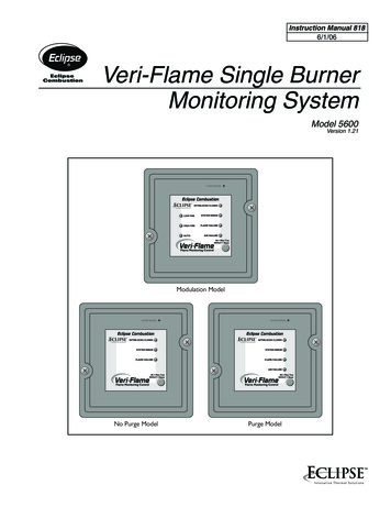
PREFACEQUICK STARTUP PROCEDUREThe purpose of this reference guide is to provide a easy to follow, step by step procedurethrough initial start up and ignition of the FID2 Analyzer Module. This procedure assumesthat the customer has already made all necessary electrical and gas connections andestablished the proper network connections.1. Turn on power to the instrument. The #1 LED (POWER) will illuminate. The #3 LED(BLOCK) will begin flashing.2. If sample gas has been connected and the sample pressure to the analyzer is sufficientto provide an accurate reading, the #4 LED (SAMPLE) will be illumninated.3. Allow the analyzer module to warm up and the burner block temperature to reach theproper minimum ignition temperature (50 C). When the burner block temperaturereaches the minimum ignition temperature, the #5 LED (IGNITE OK) will come on.4. The instrument is now ready to be lit. Lighting the burner can be conducted in one oftwo methods: a) manual ignition from the front panel of the Analyzer Module or b)autoignite from the Platform.FID 2FUEL OVERRIDEIGNITE POWERFLAMEBLOCKSAMPLE IGNITE FUEL/AIROK321LON2LON1T 6A250 V24VFIGURE P-1. FID2 FRONT PANEL748412-COctober 2000Flame Ionization Detector 2 Analyzer ModuleRosemount Analytical NGA 2000P13
PREFACEa. To light the instrument from the Analyzer Module, hold the "FUELOVERRIDE/IGNITE" switch (located to the left of the indicator lights) in the up(FUEL OVERRIDE) position for 30 seconds. Immediately move the switch to thedown (IGNITE) position. The "IGNITE" mode is automatically set to stay on for apreset time period and does not require the switch to be held down. If the lightingprocedure was successful, the #2 LED (FLAME) will begin flashing as the flametemperature rises to the correct operating temperature. Once this LED becomessolidly lit, the flame has reached operating temperature.b. To light the instrument from the Platform using the autoignite mode, simply pressthe "light" softkey shown in the "Light Flame" menu of the Platform. The AnalyzerModule will begin to go through an automated sequence of enrichment andignition similar to the manual mode described in step 5. If the burner fails to lighton the first try, the Analyzer Module will perform 2 more tries before terminatingthe autoignite sequence. If the Analyzer Module fails to light after 3 attempts, anerror message will be displayed showing the cause of the fault.5. If the burner fails to light, check all gas connections for proper gas composition andpressure, block temperature, and outlets for obstructions. Repeat step 4.6. If the flame is lit, the #2 LED will begin flashing. Once the flame temperature hasreached the correct operating temperature, the LED will remain on solid.7. If the fuel and air pressures and ratios are within proper operating parameters tosupport a continuous flame operation, the #6 LED (FUEL/AIR) will illuminate. This lightwill not be on before or during flame ignition.8. Once the burner block temperature reaches the control temperature of 80 C, the #3LED will stay on solid.9. If the instrument has been successfully lit, the temperatures are up to proper operatinglevels, and the fuel, air, and sample gases are properly adjusted to support the flameand achieve reliable results, all 6 indicator lights will be lit solid.The unit is now ready for calibration or burner optimization.P14Flame Ionization Detector 2 Analyzer ModuleRosemount Analytical NGA 2000748412-COctober 2000
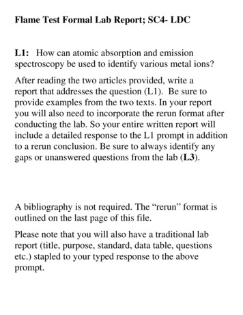
INTRODUCTION11.1 OVERVIEWThis manual describes the Flame Ionization Detector (FID2) Analyzer Module of RosemountAnalytical's NGA 2000 Series of gas analysis components. See Figure 1-1.The FID2 Analyzer Module is designed to use a flame ionization technique to measure thetotal concentration of hydrocarbon (including certain oxygenated hydrocarbons)components within the sample stream.The entire FID2 Analyzer Module is designed as a module with electrical connections at itsfront, and gas connections made from the rear. All electronics relative to sample control andsignal cond
This manual is based on the production version of the Flame Ionization Detector 2 Analyzer Module. Hardware and/or software changes may have occurred since this printing. Rosemount Analytical's NGA 2000 system of Modular Gas Analyzers and Controllers are patented,