Transcription
Valco Instruments Co. Inc.Microvolume ThermalConductivity DetectorInstruction Manualtcd2.p65Rev 4/12Printed in USANorth America, South America, and Australia/Oceania contact:Europe, Asia, and Africa contact:Valco Instruments Co. Inc.VICI AG International800 · 367 · 8424 sales713 · 688 · 9345 tech713 · 688 · 8106 faxvalco@vici.comSchenkon, SwitzerlandInt 41 · 41 · 925 · 6200 phoneInt 41 · 41 · 925 · 6201 faxinfo@vici.ch
This page intentionally left blank for printing purposes
Table of ContentsIntroductionDescription and Operating Principle . 1Safety Notes and Information . 2Components of the Detector System . 3Description of Controls and Connectors . 4System RequirementsComponents Not Included with the Detector System . 7System Purity . 7Recommended Carrier Gas Purifiers . 7Carrier Gas Selection . 7GC Column Selection . 8InstallationGeneral Precautions . 9Mounting the Detector on the GC . 9Gas Connections . 10Column Connection . 12Electrical Connections . 13Initial Power-Up . 15TroubleshootingTroubleshooting Chart . 17Heater Fault Determination . 17Detector Fault Determination . 18MaintenanceBake Out Procedure . 19Disassembly and Cleaning . 19Warranty . 20Detector Performance Log . 21
This page intentionally left blank for printing purposes
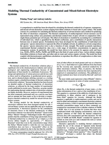
1IntroductionDescription and Operating PrincipleThe Thermal Conductivity Detector (TCD) has been one of the most popularGC detectors since the 1950’s, second perhaps only to the Flame IonizationDetector (FID). The principal of operation is based on the relative change inthe thermal conductivity of the gas passing across the detector filament ascomponents elute from the column. Heat is lost continuously by the filamentthrough the carrier gas to the cell wall of the detector. By measuring theamount of current required to maintain a constant filament temperature asgases of varying thermal conductivities cross the filament, a chromatographic signal is produced. This process is nondestructive of the sample andis concentration dependent.The Valco Microvolume TCD is unique in its implementation. Since changesin conductivity are measured only by the change in current required to keepthe filament at a constant temperature, each of the two filaments can beoperated independently without referencing these changes to a matchedfilament with reference gas. This constant temperature provides longerfilament life and safeguards it from the extremely high temperatures andoxidation which can occur with high concentrations of oxidative or corrosivecomponents. Optional signal referencing is provided to minimize backgroundvariables such as column bleed and temperature ETBFLOWINLETFigure 1: Unique dual filament designCell volume has been minimized to accommodate capillary columnchromatography and optimize the sensitivity of the detector at low flowrates. (Carrier flow rates of 1 - 10 mL/min are recommended for best sensitivity.) Thermal stability is maintained in the detector cell to within 0.010 Cdrift, giving the detector a stable, noise-free signal.The Model TCD2 is a stand-alone system which can be easily added toany chromatograph. It consists of a detector and a control module whichincorporates the electrometer and temperature controls. The detector cellincludes two separate filaments, capable of independent or referenced(differential) operation. Output signal is provided as 0-1 and 0-10 voltattenuated for chart recorders and 0-1 and 0-10 volts unattenuated forintegrators and data systems.
Introduction2Safety Notes and InformationSymbolsHOT SURFACEThe surface of the detector body may be hot while inoperation (possibly in excess of 250 C). Observe caution.ATTENTIONRefer to the manual.PROTECTIVE EARTHThis internal connection provides protection against electricshock from mains voltages and should not be removed.Installation CategoryThis equipment has been designed for installation category (overvoltagecategory) II, pollution degree 2. It has been approved for use only in heavyindustrial environments and may not be used in the residential, commercial,or light-industrial environment.SafetyThis instrument has been designed and tested in accordance with theproduct safety standard, EN61010. It has left the factory in a safecondition. This instruction manual contains important information andwarnings which must be followed by the user to insure safe operation and toretain the instrument in a safe condition. The case, chassis, and measuringterminals are connected to the protective earth contact of the mains inlet.The instrument operates with a three-conductor power cord having a protective earthing conductor and a plug with an earthing contact. The mains(line) plug shall only be inserted in a socket outlet provided with a protectiveearth contact. The protective action must not be negated by the use of anextension cord without a protective conductor. Use only with an approvedmains supply cord having a rating of 2A, 250V, or greater. Do not use thisequipment in a manner not specified herein.MaintenanceThe exterior of the instrument should be cleaned regularly with a dustingbrush. If necessary, the casing can be cleaned with a moistened cloth(99% water 1% mild detergent). Spirit or petroleum ether can be usedto remove greasy dirt. Any other cleaning agents can attack the plasticand painted surfaces.Under no circumstances should the cleaning fluid get into the instrument.Petroleum ether is flammable, and care should be taken in its use.The detector must be returned to the factory when filament replacement isrequired. Call VICI Tech Support for return authorization.
Introduction3Components of the Detector SystemsComponents of the detector system are listed in Tables 1 and 2. Check thecontents of the packages to verify that everything is present. Contact thefactory if anything is missing or damaged. (NOTE: damaged shipmentsmust remain with the original packaging for freight company inspection.)DescriptionQuantityProduct numberDetector cell, Nickel-Iron filament1TCD2-NIFEDController unit with power cord1TCD2-C2I-240101/16' zero dead volume union2ZU1CFused silica adapter for 0.53 mm ID x 0.8 mm OD capillary column2FS1R.81/16" zero dead volume nut2ZN11/16" zero dead volume ferrule2ZF1Includes:Cable, outputTable 1: Components of the TCD2-NIFE systemDescriptionQuantityProduct numberDetector cell, Tungsten-Rhenium filament1TCD2-WREController unit with power cord1TCD2-C2I-240101/16' zero dead volume union2ZU1CFused silica adapter for 0.53 mm ID x 0.8 mm OD capillary column2FS1R.81/16" zero dead volume nut2ZN11/16" zero dead volume ferrule2ZF1Includes:Cable, outputTable 2: Components of the TCD2-WRE systemSpecificationsMains (line):115/230 V 50/60 Hz, 175 VAFuse:2 A, time-delay, 5 x 20 mmPressure:6.9 kPa (1 psi) operating, 6.9 MPa (1000 psi) max.workingMaximum temperature300 CHeater power:60 W max., 48 V, PWMOutput impedance:100 Ω
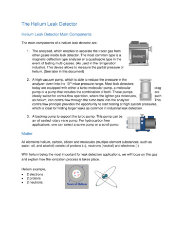
Introduction4Description of Controls and ConnectorsControls and connectors are indicated in Figures 2 and 4.MAINS switch (rear panel)Controls mains (line) voltage to the controller unit. When this switch ison ( ), the unit is operational except for the detector filaments (see nextparagraph) and the detector heater will operate if connected.FILAMENT switch and indicatorControls power to the detector filaments; when the switch is on, currentpasses through the filaments. The indicator will light even if the detectoris not connected to the controller.DETECTOR TEMPERATURE control and indicatorSets the temperature ( C) of the detector heater block. The indicator issteadily on when maximum power is being applied to the heater, steadilyoff when no power is applied, and regularly blinking on/off when the settemperature has been established.Note that due to the fail-safe mechanism designed into the temperaturecontroller, the heater will not operate if mains power is applied before theheater is connected or if the detector is too cold ( 0 C). If the heater isdisconnected with mains on, the unit must first be turned off to restorecontrol of the heater; if the unit is operated in a very cold environment,the detector should first be gently warmed without power applied.The fail-safe mechanism will also act under any condition resulting from lossof control (e.g., over-heating, RTD failure, etc.). If proper procedures havebeen followed and the controller will not heat the detector, there is causeto suspect that the fail-safe mechanism has been activated. Consult thefactory or an authorized representative. Note that the maximum temperaturefor operation of the TCD2 is 300 C.FILAMENT TEMPERATURE switchSeparate 10-turn knobs control Filaments A and B. The value displayedcorresponds to temperatures indicated in Figure 3 for nickel/iron filaments.COARSE ZERO controlOnce filament temperature has been applied, the Coarse Zero knob makescoarse adjustments of the zeroing voltage supplied for establishing thebaseline zero on both the strip chart output and the integrator outputs.FINE ZERO controlOnce coarse adjustments have been made, the Fine Zero control is used tomake fine adjustments in the output signals.ATTENUATION controlThe Attenuation control determines the attenuation of the signal for the chartoutput.RECORDER switchThe Recorder switch selects which signal is directed to the chart output.The choices are A, B, or A - B (or A minus B, which is conventionaldifferential operation with the B channel representing the reference.)The selected output signal is displayed in the LCD display.
Introduction5Figure 2: Front panel controls400350ACTUAL TEMPERATURE IN C3002502001501005000123456789FILAMENT TEMPERATURE KNOB SETTINGFigure 3: Actual filament temperature vs. filament temperature knob settings10
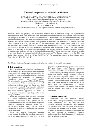
Introduction6MAINS POWER connectorFor connection to 115/230 VAC source.CHART OUTPUT connectorNormally connected to a strip chart recorder. This output has an attenuatedrange of 0-1 volt and 0 - 10 volts, with the signal scaled by the attenuationfactor set on the front panel. The output also has an internal signal reference(-) at zero volts. For best noise performance, the shield (earth) and signalreference (-) should not be connected together.UNATTENUATED OUTPUT connectorNormally connected to a data acquisition system or other recording means.For convenience, full-scale 0 - 1V and 0 - 10V outputs are provided, with aninternal signal reference (-) at zero volts. For best noise performance, theshield (earth) and signal reference (-) should not be connected together.DETECTOR connectorFor connection to the detector control and heating system.NOTE: These terminals are for connection only toequipment having no accessible live parts.MAINS POWERCONNECTORValco Instruments Co. Inc.MAINSMODEL TCD2-CT2.0A250V115/230175VA MAX.UNATTENUATEDOUTPUTCONNECTORSMAINS SWITCHOUTPUTSACHARTBA-BDETECTORCHART OUTPUTCONNECTORMODEL NO.SERIAL NO.Made in USA byValco Instruments Co. Inc.DETECTORCONNECTORFigure 4: Rear panel connectors
7System RequirementsComponents Not Included with the Detector System Carrier gas (99.999% purity is recommended) Ultra high purity grade gas pressure regulator with stainless steeldiaphragm (recommended) Any special adapters required for connection to the gas regulator Flow measuring device Flow regulating deviceSystem PuritySince detection of low concentrations depends in part on the purity of thecarrier, the purest carrier available must be used in order to achieve thelowest possible detection limit. To maintain carrier purity, extra care must betaken to assure that the delivery system is clean and free of leaks. Usestainless steel tubing (cleaned to removed manufacturing solvents) insteadof nylon or PTFE tubing, which can diffuse contaminants into the carrier.Recommended Carrier Gas PurifiersThe Valco Helium Purifer (product number HP2) and Nitrogen Purifer (productnumber NP2), which utilize a rare earth gettering alloy to effectively removecontaminants, are recommended for ppm level analysis of permanent gases.For other applications, economical and convenient VICI Mat/Sen purifiers areappropriate. Order the P300-1 for nitrogen, P200-1 for hydrogen, or theP100-1 for helium and other inert carrier gases.Carrier Gas SelectionThe detector’s response to a component is based upon the differencebetween the thermal conductivities of the component and the carrier gas: thegreater the difference, the greater the response. The table below showsthermal conductivities for a variety of light rbon monoxideWaterArgonCarbon dioxide45.936.911.88.66.66.46.46.24.54.54.2As an example, note in the table that the thermal conductivity of hydrogen is46 and helium is 37, while nitrogen is only 6 and argon is even lower at 4.Since the largest difference in thermal conductivity yields the best response,detection of small amounts of hydrogen is better done with argon or nitrogencarrier than with helium.
System Requirements8However, while nitrogen as a carrier yields excellent response to hydrogen,the response to oxygen and carbon dioxide is diminished compared to thelevels that could be achieved with helium or hydrogen. Argon would yieldpoor response to carbon dioxide and water, but would be adequate for othercomponents.There is no absolute “best choice” of carrier gas. For any situation, the choicemust take into account all of the parameters involved: columncharacteristics, components of interest and their concentrations, safetyconsiderations, carrier cost, etc.GC Column SelectionCell volume has been minimized to accommodate capillary, megabore, andmicropacked columns, and to optimize the sensitivity of the detector at lowflow rates. However, standard packed columns may also be used if sensitivity is not an issue.2 13 16"5 5 8"1 1 4"1 1 2"1"3"6"Figure 5: Detector assembly mounting dimensions
9InstallationThe detector is usually mounted on top of the GC column oven. The powercord for the controller is 1.8 m (6') long; the detector cable and the signaloutput cables (attenuated and unattenuated) are 1.2 m (4') long.General Precautions Do not turn the unit on until the carrier gas is flowing through the detector. Do not shut off or disconnect the carrier gas when the detector is hot,even if the unit is turned off. Turn off the power switch on the back of thecontroller and allow the detector to cool down naturally before disconnecting or shutting off the carrier gas. Position the controller unit where the mains switch on the rear panel canbe reached easily.Mounting the Detector on the GCVertical MountingCHANNELAVENTThe detector has no particular orientationrequirements, but it should have adequatethermal isolation from the column oven andinjection port. Most GCs have an existingopening which will allow the TCD2 to sitvertically on top of the column oven with thecolumn inlet extending into the oven. If youare replacing an existing detector, you canusually just remove it and set the TCD2 in itsplace. If not, use a drill or chassis punch todrill a hole of the proper size, and set thedetector in position.CHANNELAINLET(gold ferrule)CHANNELBVENTCHANNELBINLET(stainless ferrule)Figure 6: Detector connectionsWhile trying to match base plate mounting holes to every GC on the marketis impractical, we have located the mounting holes so that at least two ofthem will coincide with existing holes on the GC. (Refer to Figure 5.)Orient the detector to allow for easy cable and gas connections. The inletlines installed into the detector must enter the column oven and permitcolumn connection. Temperature loss between the column outlet and thedetector should be minimized to prevent possible condensation of thesample.CAUTION: Do not mount the detector near the columnoven cool-down vents.Horizontal MountingSome older GCs have access to the column oven through the side of theGC. This does not present a problem as far as operation of the TCD2 isconcerned. Drill a hole at the appropriate location, orient the detector forconvenient connection, and mark the position of the mounting holes. Drill themounting holes and secure the detector to the side of the GC with four sheetmetal screws (not supplied).
Installation10Gas ConnectionsRemember these three points discussed earlier: (1) all surfaces that contactthe gas stream must be glass or stainless steel; (2) do not use copper tubingor brass fittings; and (3) all tubes must be thoroughly cleaned and bakedbefore use. The installation instructions below assume that the detectorcarrier will be supplied from a nearby cylinder. If your installation is different,you may need to modify the instructions appropriately. Consult the VICIcatalog or vici.com for any fittings and tubing required.The figures below illustrates gas connections for a typical TCD2 detectorsystem, in referenced and unreferenced modes. Since the distance from thecarrier supply to the GC varies from installation to installation, we do notsupply tubing to go from that point to the GC.CHANNELBVENTCHANNELAVENTDETECTORCHANNEL AINLET(gold ferrule)CHANNEL BINLET(stainless TORCARRIER GAS(99.999% purity)GAS CHROMATOGRAPHFigure 7: Referenced mode (A - B)CHANNELBVENTCHANNELAVENTDETECTORCHANNEL AINLET(gold ferrule)CHANNEL BINLET(stainless ferrule)PURIFIERTEE(ZT1)CARRIER GAS(99.999% GAS CHROMATOGRAPHFigure 8: Unreferenced mode
Installation11Installing and Purging the Gas Regulator1. Make sure the on/off valve on the helium cylinder is completely closed.Screw the CGA fitting nut of the regulator into the helium cylinder. Gobeyond finger-tight, but do not tighten the nut all the way – some leakageis required for the purging operation.2. Turn the output pressure regulating knob completely counterclockwise.3. Open the cylinder on/off valve slightly and quickly close it again.4. Adjust the tightness of the regulator connecting nut to allow a pressurereduction of 690 kPa/sec (100 psi/sec). With a new bottle, the gaugeshould start out at about 14 MPa (2000 psi).5. When the pressure drops into the 1.4 - 3.4 MPa (200 - 500 psi) range,open the cylinder on/off valve slightly and quickly close it again.6. Repeat Step 5 eight or ten times to be certain that all the air is purged.On the final purge, tighten the regulator connecting nut very securely asthe pressure approaches the 2.1 - 3.4 MPa (300 - 500 psi) range.7. Open the cylinder valve to pressurize the regulator once again, then closeit and observe the high pressure gauge needle for 15 minutes. If it doesn’tmove, there is no critical leak on the high pressure side of the regulator.CAUTION: Never use leak detecting fluids on any part ofthis system.Installing and Purging a PurifierEZR211. If the pressure regulator has a 1/8" male cone-type outlet port, installthe Valco 1/8" external to 1/16" internal reducer (EZR21); if it has a 1/4"male cone-type outlet port, install the Valco 1/4" external to 1/16" internalreducer (EZR41). For other regulator outlet fittings, a wide variety of Valcoadapters are available.2. Remove the cap from the inlet tube of the Valco helium purifier and insertthe tube fitting into the 1/16" reducer port. (Keep the outlet tube capped.)Use a 1/4" wrench to turn the nut one-quarter turn past the point where theferrule first starts to grab the tubing. Do not remove the fitting. Whenmade up properly, it should be leak-tight.3. Turn the output pressure regulating knob clockwise until the gaugeregisters 345 KPA (50 psi).4. Allow five minutes for equilibration, then turn the regulating knob all theway counterclockwise.5. Observe the needle of the output pressure gauge for 15 minutes. Therewill be a slight initial drop, but if it doesn’t move after that, consider thatall the connections are tight.6. If necessary, use an electronic leak detector to locate any leaks. If aleak detector is not available, tighten all the fittings (including the outputpressure guage), and repressurize the system for another test.7. Upcap the outlet tube of the purifier and purge the system for 15 to 30minutes at 60 - 80 mL/min to eliminate air from the purifier getter material.
Installation12Column ConnectionTo prevent detector contamination, we strongly recommend disconnecting the column from the detector duringcolumn bakeout procedures.Referenced modeIn the referenced mode, the column is connected to the Channel A inlet, andthe carrier gas stream is split and used as a reference in channel B. The gasflow rate from both channels must be the same (flow balanced). This modeof operation provides the best baseline stability and the least backgroundnoise.Unreferenced modeIn the unreferenced mode, Channels A and B are used independently. Onecolumn connects to the Channel A inlet, and the other to Channel B. Thecarrier gas must be the same for both channels.It is also possible to use only one channel with the other capped off, as longas the filament temperature control knob of the unused channel is set tozero.The unreferenced mode has certain limitations: there is a possibility ofdetector cross-talk (interference) if compound concentrations exceed 1%,and baseline drift and background noise are greater than with the referencedmode.To make column connection as convenient as possible, each TCD isshipped with two Valco 1/16" unions (Product No. ZU1C) complete withnuts and ferrules (Product Nos. ZN1 and ZF1). Also included are two fusedsilica adapters (FSR1.8) for use with .53 mm ID wide bore capillary columns(.8 mm OD). Refer to the information below to determine the correct Valcofitting for use with other columns.Column Connection FittingsPacked ColumnsA 1/16" packed column requires only the ZU1C which comes with the TCD.For 1/8" columns, order a ZRU21.ZU1CUsed with 1/16" columnZRU21Used with 1/8" column
Installation13Packed Columns with Swagelok -type Female NutThe connection of these columns is similar to that for standard packedcolumns, but requires a union which adapts the female nut to the Valcofitting.EZU1Used with 1/16" columnEZRU21Used with 1/8" columnCapillary ColumnsConnection of these columns requires the use of the ZU1C with the appropriate fused silica adapter. For a .53 mm ID x .8 mm OD column, use theFSR1.8 supplied with the TCD. For other sizes, use this table to determinethe proper adapter:Column size.32 mm ID x .5 mm OD.25 mm ID x .4 mm OD .2 mm IDAdapter requiredFS1R.5FS1R.4FS1R.2ZU1C with fused silica adapterTesting for LeaksIt is critical for the system to be leak-tight, and an additional check at thispoint can save many headaches later on. To test for leaks:1. Insure that both outlets are capped.2. Pressurize the entire system with helium to 138 kPa (20 psi).3. If the system does not hold pressure, check all the fittings with anelectronic helium leak detector. DO NOT use leak detecting liquids.Electrical ConnectionsBefore connecting the detector cable to the controlmodule, make sure that the control module power cord isunplugged.1. The heater and filament connections from the detector to the rear panel ofthe controller are made up in one cable. After making sure that the controlmodule power cord is not plugged in, connect this detector cable to theconnector on the control module. The cable connector should be firmlyseated by turning the coupling ring clockwise until the detent is felt.For best detector performance, the cable and connectorshould not be allowed to move while measurements arebeing made. If the cable is disconnected, exercise careto keep the connecting pins in each connector clean.
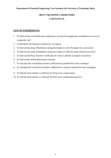
Installation142. Connect the data output(s). The A / B / A - B outputs are used with anintegrator or PC-based data acquisition system; the chart output is for astrip chart recorder. Polarities and full scale range are indicated in thefigure below. (Set the recorder/DAQ for the same voltage scale.)3. Connect the main power cord.Valco Instruments Co. Inc.MAINSMODEL TCD2-CT2.0A250V115/230175VA MAX.220VOUTPUTSACHARTRED ( 10V)BLACK ( )WHITE ( 1V)RED ( 10V)BLACK ( )WHITE ( 1V)ATTENUATED STRIPCHART OUTPUTMODEL NO.BSERIALA-BNO.Valco Instruments Co. Inc.CABLES FOR A, B,and A BCHANNELACHANNELBINLETAINLETBFigure 9: Electrical connectionsDETECTOR
Installation15Initial Power-UpSince the TCD is a concentration-dependent detector, the lower the flowrate through the detector, the higher the sensitivity. Column diameter willdetermine the optimum column flow rate.The microvolume TCD is designed for the lower flow rates typical for capillarycolumns, and achieves best sensitivity at rates below 10 ml/min. Since thefilaments are maintained at constant temperature, the detector can beoperated at extremely low flow rates (less than 0.5 ml/min) without damageto the filaments.A - B referenced modeFlow Rate Settings1. Measure the column flow at the detector’s Channel A out. The optimumflow rate is in the range of 4 - 20 mL/min, with the actual rate dependenton the type of column used.2. Measure the reference gas flow at Channel B out. It should be as close aspossible to the GC column flow. Use a fixed flow restrictor or a goodquality flow controller to match the the carrier gas and reference gas flows.3. Once the flows have been established, make sure the filament switch andthe main power switch are in the OFF position, and plug the power cordinto an AC main outlet.Initial Conditioning4. Turn on the control module main power switch and set the detectortemperature to 220 C.5. Turn on the filament power switch and set both filament temperature knobsat 8.0.6. Condition the detector by allowing it to bake at these settings for at least12 hours.Temperature Settings7. After the initial bakeout period, set the detector temperature at 100 C or atthe column temperature plus 30 , whichever is higher.8. Set the filament temperatures at least 50 and as much as 100 higherthan the detector temperature. Refer to Figure 3 on page 5, whichoutlines the relationship between the filament temperature knob settingsand the actual filament temperature.Detector sensitivity increases as the temperature differential between thedetector and the filaments increases, but filament life decreases as itstemperature increases. Thus, the detector temperature should be set aslow as possible, determined by the boiling point of the highest boilingcomponent of the sample.9. Once all temperatures are set, allow plenty of time for the system toequilibrate, evidenced by a stable baseline. Typical equilibration time forgoing from a cold start-up to 130 C detector temperature is approximatelyfive hours. Detector temperature changes take much longer to equilibratethan do filament temperature changes.
Installation16The test chromatogram accompanying your TCD was obtained under thefollowing conditions:Sample: 100 ppm blend in Helium balanceSample volume:250 µlColumn:10' x 1/16" x 0.040" molecular sieve 5Å micropackedColumn flow:6 mL/minReference flow:6 mL/minColumn temperature: 65 CDetector temperature: 100 CFilament temperature: 230 C (a setting of 5.0)Carrier gas:HeliumBalancing the Channels using LCD DisplayThe LCD display indicates the signal level from the recorder/chart output.10. Set the recorder switch to A, and use the coarse and fine controls forChannel A to adjust the signal level to about 300 mv.11. Set the recorder switch to B and repeat the same process to adjust thesignal level to about 200 mv.12. Set the recorder switch to A-B. The display should read about 100 mv. Ifthe signal levels drifts below zero, readjust the A & B channels.The detector is now ready for analytical use.Balancing the Channels using Recorder/Chart Output10. Use the zero (or shunt) setting on the recorder to set the true zero on the recorder.11. Set the Recorder switch to A, and use the coarse and fine zero controlsfor Channel A to bring the recorder pen on scale and to a positionapproximately 1-2 cm above zero.12. Set the Recorder switch to B, and repeat the same process, bringing thepen to a position half as far above zero as the pen for Channel A.13. Set the Recorder switch to A - B, and observe the recorder pen position.It should be above the true zero position, but below the position forChannel A. If the pen drifts below zero, readjust the A and B channels.The detector is no
The Thermal Conductivity Detector (TCD) has been one of the most popular GC detectors since the 1950's, second perhaps only to the Flame Ionization Detector (FID). The principal of operation is based on the relative change in the thermal conductivity of the gas passing across the detector filament as components elute from the column.