Transcription
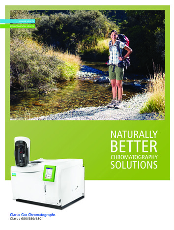
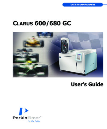
GAS CHROMATOGRAPHYCLARUS 600/680 GCUser’s Guide
Clarus 600/680 GCUser’s Guide
Release HistoryPart NumberReleasePublication Date09936780CFebruary 2010Any comments about the documentation for this product should be addressed to:User AssistancePerkinElmer, Inc.710 Bridgeport AvenueShelton, Connecticut 06484-4794U.S.A.Or emailed to: info@perkinelmer.comNoticesThe information contained in this document is subject to change without notice.Except as specifically set forth in its terms and conditions of sale, PerkinElmer makes nowarranty of any kind with regard to this document, including, but not limited to, the impliedwarranties of merchantability and fitness for a particular purpose.PerkinElmer shall not be liable for errors contained herein for incidental consequential damages inconnection with furnishing, performance or use of this material.Copyright InformationThis document contains proprietary information that is protected by copyright.All rights are reserved. No part of this publication may be reproduced in any form whatsoever ortranslated into any language without the prior, written permission of PerkinElmer, Inc.Copyright 2010 PerkinElmer, Inc.TrademarksRegistered names, trademarks, etc. used in this document, even when not specifically marked as such,are protected by law.PerkinElmer is a registered trademark of PerkinElmer, Inc.ii
2Table of ContentsIntroduction . 1-1About This Manual . 1-3Conventions Used in this Manual . 1-4Notes, cautions and warnings . 1-4Warning Signs on the Instrument. 1-5Screen Abbreviations . 1-6Glossary of Clarus GC Terms . 1-7Autosampler Terms . 1-7Instrument-Specific Terms. 1-8Glossary of Chromatographic Terms . 1-10Touch Screen Navigation . 2-1Chapter Overview . 2-3Touch Screen . 2-4Tabs. 2-6Non-Configured Devices . 2-6Non-installed Devices . 2-7Run Button . 2-8Stop Menu. 2-11Signal Button . 2-11Heated Zones . 2-13Navigation Bar . 2-16Injectors . 2-17Program Buttons . 2-18Display Text. 2-18PSS. 2-18Packed (Pkd) . 2-24POC. 2-28Capillary (Cap) Injector . 2-29Oven . 2-30Aux Zone . 2-31Detectors . 2-32FID . 2-32TCD . 2-36ECD . 2-37PID . 2-39NPD . 2-40FPD . 2-41Timed Events . 2-42iii
Events Tab . 2-42Timed Events Table . 2-43Using the Active Method . 3-1Overview . 3-3Editing the Active Method . 3-4Getting Ready to Edit the Active Method. 3-5Setting Up Oven and Inlet Temperature Programs . 3-6Configuring the Equilibration Time (Init) . 3-7Setting a Coolant Timeout Value. 3-7Setting a Coolant Cut-In Temperature . 3-8Setting Up an Isothermal Program. 3-8Setting Up a One-Ramp Temperature Program . 3-10Holding an Oven Temperature . 3-11Setting Injector Temperatures . 3-14Displaying Injector Temperature Screens. 3-14Turning Injector Heaters On or Off . 3-16Changing Injector Temperatures . 3-16Oven Temperature Programming Mode . 3-17Inlet Temperature Programming Mode . 3-18Setting Up a One-Ramp Injector Program . 3-19Viewing/Setting Carrier Gas Pressure/Flow/Velocity . 3-21Setting Carrier Gas Pressure . 3-23Setting Carrier Gas Flow using PPC. 3-25Viewing/Setting Carrier Gas Velocity . 3-27Setting the Septum Purge Mode and Offset . 3-29Setting Up Valves . 3-37Setting the Split Mode Using PPC . 3-37Set up the Splitless Mode for a CAP or PSS Injector . 3-41Splitless Injection with Pressure Pulse (Flow Pulse, Velocity Pulse) Technique . 3-41Contolling the Autosampler . 3-51Autosampler Trays and Carousel. 3-51Autosampler Touch Screen. 3-53Start Button . 3-54Stop Button . 3-55About Waste and Wash Vials . 3-62Multi-Program Mode . 3-62About Sample Vials . 3-63Using a TCD with the Autosampler . 3-63Available Syringes . 3-64Setting Up the Detectors . 4-1Overview . 4-3iv
2FID Overview . 4-5Setting Up an FID . 4-6Automatically Ignite the Flame . 4-11Manually Ignite the Flame . 4-13Using the FID in Corrosive Environments . 4-15Setting up an ECD . 4-17United States Government Regulations for ECDs . 4-17Special Instructions for ECD Cell Purchasers . 4-18United Kingdom Regulations . 4-20ECD Overview. 4-20ECD Set Up . 4-22Setting up a TCD . 4-28TCD Setup . 4-29TCD Setup Summary . 4-29Using a TCD with the Autosampler or GSV . 4-35Setting up a PID . 4-36PID Overview . 4-36PID Setup . 4-37Setting Up a NPD. 4-43NPD Overview. 4-44Setting Up a NPD . 4-45NPD Bead Activation Procedure . 4-48Setting up an FPD . 4-55FPD Overview . 4-55Setting Up the FPD . 4-57FPD Setup Summary . 4-57Configure the Linearizer and Signal Filter . 4-57Set the FPD Temperature. 4-61Detector Temperatures . 4-72Setting the Range . 4-74Setting the FID, PID, or NPD Range . 4-74Changing the FID, PID, or NPD Range During a Run . 4-75Setting the TCD Current (Filament Current) . 4-78Changing TCD Polarity During a Run. 4-80Routing Detector Output . 4-83Rerouting Output . 4-83Attenuating Detector Signals Going to a Recorder . 4-87Optimizing a Detector Signal to an Integrator for Maximum Sample Dynamic Range 4-89Matching Detector Signals with Your Integrator . 4-90Autozeroing a Detector . 4-93Using the Method Editor . 5-1v
Method Editor . 5-3Method Edit Mode . 5-5Oven Settings . 5-7Managing Methods . 5-9File Menu . 5-9Using the Tools Menu . 6-1Tools Menu . 6-3Method Editor . 6-4Event Log . 6-5Maintenance . 6-6Configuration . 6-10Injectors (Deconfiguring and Configuring Injectors) . 6-10Oven . 6-18Detectors . 6-20Run/AutoSampler . 6-26Setup . 6-28Pneumatics . 6-33Connecting the PPC Modules . 6-35Reference Settings . 6-48Relays . 6-48Zeroing and Calibrating the PPC Modules . 6-49Zeroing the PPC Gas Modules. 6-49Setting the Reference Temperature and Pressure . 6-53Calibrating the Carrier Gas Modules . 6-54Calibrating the Detector Gas Modules. 6-57Calibrating the Oven Temperature. 6-60Calibrate the Reference Thermometer . 6-60Place the Thermometer Probe in the Oven . 6-61Equilibrate the Oven Temperature . 6-62Enter the Required Offset Value . 6-65Remove the Thermometer Probe . 6-65Utilities. 6-66Column Flow Calculator. 6-67Split Flow Calculations Screen . 6-71Column Length Calculator. 6-73Background Compensation . 6-74Stopwatch . 6-76Program (Max Oven Program Rates). 6-77Release . 6-78Logout . 6-79About . 6-80vi
2Setting up a Typical Analysis . 7-1System Status Screen . 7-4Injector Settings . 7-6Packed Column (PKD) Injector . 7-6Programmed Split/Splitless (PSS) Injector . 7-8Detector Settings . 7-11Flame Ionization Detector (FID) . 7-11Detector . 7-16Thermal Conductivity Detector (TCD). 7-16Autosampler . 7-22Indexvii
viii
Introduction1
Introduction1-2
Clarus 600/680 GC User’s GuideAbout This ManualThis guide is divided into following chapters:Chapter 1 IntroductionThis chapter contains a brief introduction to the Clarus GC, the conventions andwarnings used in the manual.Chapter 2 Touch Screen NavigationThis chapter contains information that introduces you to the look and feel of thetouch screen. It shows you how to turn on the GC, check the status, and performfundamental operations such as changing parameters, selecting options, using thetools menus, etc.Chapter 3 Active MethodThis chapter contains step by step explanation of the active method. Detailedinformation on setting up the autosampler is contained in this chapter.Chapter 4 Setting Up the DetectorsThis chapter contains detailed information on setting up the detectors.Chapter 5 Using the Method EditorThis chapter describes how to modify, save and use the method editor.Chapter 6 Using the Tools MenuThe chapter contains detailed information on the tools menu section of the touchscreen.Chapter 7 Setting Up a Typical AnalysisThis chapter describes how to run a typical analysis on the Clarus GC using themost common configuration.1-3
IntroductionConventions Used in this ManualNormal text is used to provide information and instructions.Bold text refers to text that is displayed on the screen.All eight-digit numbers are PerkinElmer part numbers unless stated otherwise.Notes, cautions and warningsThree terms, in the following standard formats, are also used to highlight specialcircumstances and warnings.NOTE: A note indicates additional, significant information that is provided with someprocedures.CAUTIONWe use the term CAUTION to inform you about situations thatcould result in serious damage to the instrument or otherequipment. Details about these circumstances are in a box like thisone.We use the term WARNING to inform you about situations thatcould result in personal injury to yourself or other persons. Detailsabout these circumstances are in a box like this one.WARNING1-4
Clarus 600/680 GC User’s GuideWarning Signs on the InstrumentFor detailed safety information see the Safety Practices chapter in the Clarus600/680 GC Customer Hardware and Service Guide (P/N 09936781).Caution, hot surface.Caution, risk of electric shock.Caution, laser radiation hazard.Caution (refer to accompanying documents).1-5
IntroductionScreen AbbreviationsAUX – Auxiliary zoneCap – capillary split/splitless injectorCmptr – computerCtrl – syringe control parametersECD – Electron Capture DetectorFID – Flame Ionization DetectorFPD – Flame Photometric DetectorGen – generateInj/Vial – injections per vialInt – integratorkPa – kilopascalsNPD – Nitrogen Phosphorus DetectorPID – Photoionization DetectorPkd – packed injectorPOC – Programmed On-Column InjectorPPC – programmed pneumatic controlPre – # of preinjection syringe washesPsi or psig – pounds per square inch (gauge)PSS – Programmed Split/Splitless Capillary InjectorTCD – Thermal Conductivity Detector1-6
Clarus 600/680 GC User’s GuideGlossary of Clarus GC TermsThe glossary of Clarus GC terms are divided into two types: Autosampler Terms Instrument-Specific TermsAutosampler TermsTermDescriptionWashesWashing the syringe.Pre-WashThe number of prewashes of sample to prime the syringe(no pumping).Pre-InjectThe number of pre-injection syringe washes with a solvent.Post-InjectThe number of post injection syringe washes with asolvent.PumpsThe number of times the syringe draws up sample andevacuates it before acquiring the volume. This is done toeliminate bubbles.ModeThe style of injection.FastFast speed of the syringe during sample injection. This isused to eliminate discrimination in the needle.NormalNormal speed of the syringe during sample injection.SlowSlow speed of the syringe during sample injection in orderto inject directly into a wide-bore capillary column, in hotinjection port.1-7
IntroductionInstrument-Specific Terms1-8TermDescriptionAttenuationThe amplification of the detector output signal.BackgroundcompensationA routine that automatically subtracts a stored calibratedbaseline profile from the signal generated during a GC run.BallisticallyChanging the oven temperature as quickly as possible toreach a set point.Soft CoolingSoft-cooling is a technique whereby, the cooling rate of theGC oven is initially limited by controlling (throttling) the intakeof the ambient (cold) air used to cool the oven.DetectorbackgroundThe detector output signal when no components are beingeluted.EquilibrationThe delay time after the method set points have beenreached before the system becomes READY.FlameoutDetects if the flame is on to prevent injection into anonfunctioning system and subsequent loss of sample.IsothermalmethodA method in which the oven temperature remains constantthroughout a GC run.MethodA collection of parameters that control the GC.Negative-timeeventA timed event that you set to occur before the instrumentbecomes READY.
Clarus 600/680 GC User’s GuideTermDescriptionParameterAn independent variable used to specify a condition to bemet.PPC Programmable Pneumatic ControlPre-runThe time after equilibration during which negative-time eventsare executed.PreVent PPC version only. Sample management system.RangeFor a Flame Ionization Detector, range means sensitivity ofthe detector output signal.ReadyIndicates that all method parameters have reached their setpoints and that you can start your analysis.RunThe time from sample injection to the end of the oventemperature program.Sleep modeThe GC can be set to a predefined method for gas savings.TemperatureprogramPPC version only. A program that specifies the rate of oventemperature increase from one plateau to the next, and thetime the oven temperature is held constant at a plateau.Timed EventsEvents that take place before or during a GC run as specifiedin a timed events table.ZoneA heated area in the GC oven, injector, or detector.1-9
IntroductionGlossary of Chromatographic Terms*Adsorption – A process that occurs at the surface of a liquid or solid as a result ofthe attractive forces between the adsorbent and the solute. These forces may bephysical or weakly chemical.Analysis – The complete investigation of a sample by gas chromatographicseparation including identification of the sample components and quantitativemeasurements.Anode – The positively charged electrode in any electrical circuit to whichcharged particles and ions are attracted.Band Broadening – A process that occurs in the GC whereby the peak width fora component increases the longer the component travels through the column.Baseline – The detector signal to a recorder or integrator when only the carriergas is passing through the detector.Baseline drift – Any regular change occurring in the baseline signal from thedetector, usually resulting from column temperature and/or gas flow changes.Blank run – A run without the sample being injected.Bleed – The evaporation of the stationary phase from a column.Capillary column (wall coated open tubular column) – A small-internal-diametercolumn whose inside wall is coated with a liquid phase.Carrier gas – The mobile phase of the separation system. An inert gas whichtransports the sample from the injector through the column to the detector. Thisgas is usually helium, hydrogen, or nitrogen.Column conditioning – A process for producing a stable column by heating thecolumn with carrier gas flowing to remove volatile impurities from the stationaryphase.Detectors – Hardware that responds to sample components producing anelectrical signal that can be measured to quantitate the amount of eachcomponent present.Flow programming – The stored PPC program is interpreted as real columnmass flow settings or capillary column flow settings from which the inlet*Reference: Denney, R.C. A Dictionary of Chromatography.1-10
Clarus 600/680 GC User’s Guidepressure is calculated. This
Except as specifically set forth in its terms and conditions of sale, PerkinElmer makes no warranty of any kind with regard to this document, including, but not limited to, the implied
