Transcription
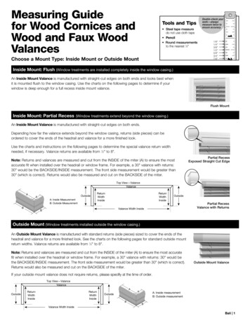
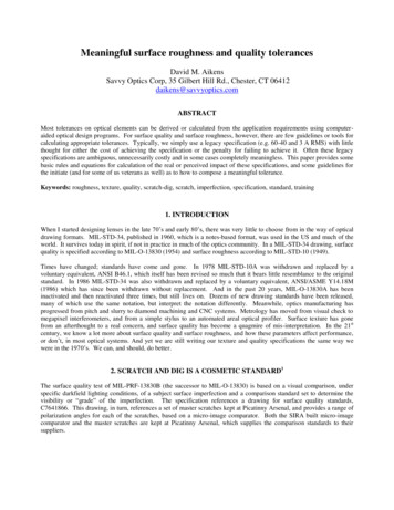
NPFLEX-LAProduction Interface3D Lead AngleMeasurementNon-Contact OpticalProfilingApplication Note #549Quantitative 3D DataQuantitatively Measuring Surface Texture andShaft Lead of Dynamic Sealing SystemsThe average automobile has over eighty dynamic seals thatcan fail at any given time.1 Failures attributed to leakingseals cost the transportation and power industry many tensof millions of dollars a year in warranty costs, recalls andfines. Advances in seal/shaft design and materials haveextended the service life and reliability of vehicles andengineered systems. However, traditional measurementtechniques are unable to keep pace with today’s smoothershafts and more rigorously controlled seal interfaces.Tighter specifications demand a more robust, gage-capablemetrology solution that can quantitatively measure leadangles to the tolerances outlined in industry specifications,such as ISO 6194-1:2009 and RMA OS-1-1 rev. 2004,thereby improving production quality and yield. Thisapplication note details a metrology solution that addressesthese issues and provides manufacturers a way to measurelead angle both quantitatively and repeatably with completeconfidence in the results.Shaft Surface TextureShaft surface texture and machine lead are critical tomaintain minimal fluid leakage and friction for rotarydynamic seal applications.2 For optimum performanceelastomeric radial lip seals require a precise shaft surfacetexture and zero machine lead angle. When initially run, theprimary lip of a new seal contacts the shaft and begins towear. If the surface texture of the shaft is too rough theseal is quickly worn away, leading to a leak. Conversely, ifthe shaft is too smooth, the seal will not bed correctly, andagain will cause failures. Ideally, the shaft surface textureneeds to be such that the lip wear is sufficient to allowa small quantity of fluid (typically of the order of 0.25umthick) to enter the shaft-seal interface. At this point thelip wear stops and the sealing system is deemed to be inequilibrium. It should be noted that the lip seal actually runson a fluid film.Of equal importance is the absence of machine lead, alsoknown as “shaft lead,” “lead angle,” or simply “lead.” Thereare two lead paradigms that need consideration, namelymacro and micro lead.3 Macro lead is an axial periodicstructure that is singularly or multiply circumferential, whilemicro-lead is generally used to describe high-frequencyfeatures on the shaft, either periodic or non-periodic, whichare tilted with respect to the workpiece.The introduction of lead angle on a shaft is inherent in allshaft manufacturing processes. Two of the many factorsthat contribute to the overall lead angle of a shaft are the
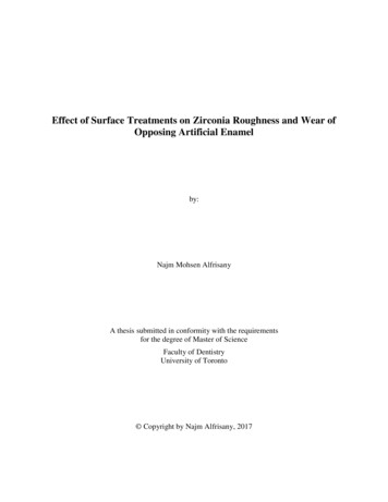
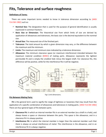
feed rate of the cutting tool for a turned shaft, and the partorientation during turning of either the workpiece or grindingdisc. Fine helical shaped grooves are thus inadvertentlymachined into the shaft during the manufacturing process.In actual operation, as the shaft rotates this helical patternleads to a “wicking” of the lubricant through the shaft-sealinterface. A left hand (LH) lead is defined as that whichmoves the application oil in the direction of the source,causing the seal to dry out, while a right hand (RH) leadpulls lubricant away from the seal, causing the seal to leak.The issue of measuring lead angle is not new to theautomotive and precision manufacturing industries. Overthe past decades, investigations have been performed tounderstand the shaft surface texture and lead requirements.The International Standards Organization (ISO) recommendsin their document ISO 6194-1:2009 that the seal contactsurface shall normally be free of machining leads.4 Similarly,the Rubber Manufacturers Association of North America(RMA) RMA OS-1-1 rev. 2004 specifies a lead angle ofzero degrees 0.05 degrees for shaft lead.5 Both of thesestandards also list shaft surface roughness parametersthat are coupled with the lead angle specification. Table 1provides a summary of both the RMA OS-1-1- rev. 2004and ISO 6194-1:2009 specifications for lead angle andsurface roughness.flatten and don’t track lead, nor should un-waxed dentalfloss due to its tendency to wrap around the shaft as itrotates. The shaft is center balanced so that the string/weight assembly can translate along the shaft. Movementalong the shaft can be measured using an optical eyepiecewith a vernier scale or precision calipers. The shaft isrotated in both the clockwise and counter clockwisedirections, and if the thread translates in both directionsit signifies the presence of a lead angle. This lead angleis then determined via the formula: Arc Tan A Threadadvance per shaft revolution/shaft circumference.The String MethodWhile the string method is relatively cheap to implement,it is not particularly reliable since it is influenced by thegeometric accuracy of the shaft, lubricant type, surfacefinish, and the actual string used in the testing. In addition,some authors have reported a dead-band or lack ofresponse when measuring 0.03 degrees of shaft lead.6Shafts with lead of less than 0.05 degrees often have sucha dead band, which leads to the broad designation of “nolead” as being from 0.05 degrees RH to 0.05 degrees LH.Furthermore, many parts, such as those with yokes orgeared ends, must have non-cylindrical components cut offfor proper measurement, causing the string method to bea destructive test, and thus not allowing the test of partsto be put into actual operation. Also, certain surfaces havelarge lead angles where the string moves quickly to the endof the shaft, and thus may not have sufficient resolutionto measure the lead. A final limitation of the method isthat since the string must translate a significant distanceto achieve good accuracy, localizing measurements in thecritical seal contact areas is not possible.For determining shaft lead angle, RMA OS-1-1 rev. 2004outlines a methodology for measuring the angle via theuse of a string and weight. The string method suspendsa 30g weight from a length of 0.23mm diameter quiltingthread draped across the shaft under investigation in sucha way that the thread-weight assembly makes an arc ofcontact with the shaft surface ranging between 220 and240 degrees. Nylon lines should not be used because theyThe general sentiment throughout the precisionmanufacturing sector is that while the string methodwas acceptable at the time the RMA OS-1-1 rev. 2004standard was developed, it is deemed unviable for today’sautomotive, aerospace and general precision machiningindustries due to the increased constraints placed onmachined parts and the increased difficulty in acquiring100% cotton quilting thread.In addition to defining the requirements, the RMA standarddiscusses possible methods for measuring the parameters,namely the string method for lead and a stylus profiler forsurface texture:Table 1. Shaft surface texture/lead specificationsISO 6194-1: 2009RMA OS-1-1 rev. 2004Shaft LeadFree of machining lead. i.e. zero lead angle 0 0.05 degreesSurface TextureRa 0.2µm to 0.5µmRz 1.2µm to 3µmRa 0.02 to 0.43µmRz 1.65 to 2.90µmRpm 0.5 to 1.25µmStylus Instrument Parameters0.25mm (0.01in) cutoff5µm 90 diamond stylusDigital 50% Gaussian phase-corrected filter2
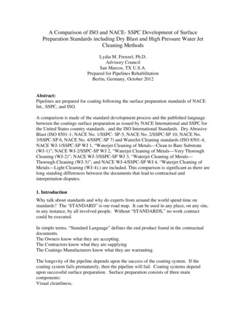
String MethodFigure 1b. Shaft is rotated both clockwise and counterclockwiseto inspect string traverse.Figure 1a. Typical string method assembly with testshaft mounted.Figure 1c. Distance of string traveled is measured with verneers.Stylus MetrologyTraditionally, shaft surface texture has been measured witha stylus, or contact profilometer. While stylus profilometersare indeed useful, there are limitations in measuring surfaceparameters, such as Ra, Rz and Rpm. It is important tounderstand that these 2D R-parameters were createdin the 1930s and have remained relatively unchangedthough surface finishing techniques have greatly advanced.While parameters such as Ra remain useful as a generalguideline of surface texture, 2D parameters typicallyprove too general to describe the surface’s functionalnature. For example, a surface with sharp spikes, deeppits, or general isotropy may all yield the same averageroughness value. Ra makes no distinction between peaksand valleys, nor does it provide information about the spatialstructure of the surface. In addition to the ambiguity thataccompanies measurement of Ra, Rz and Rpm, the stylustool itself can contribute to error in the measurement.The stylus is generally placed on the part and translatedacross the sample surface. Shaft alignment is critical, asthe stylus orientation with respect to the shaft will affectthe measured roughness. Even if the stylus scan beginswith the stylus translating parallel to the shaft, the tip cansometimes catch in a groove and translate off-axis.These 2D R-parameter limitations are well knownthroughout the precision manufacturing industry.To overcome this, the ISO has developed a setof comprehensive 3D surface parameters, calledabFigure 2. Surface textures can vary widely while their Ra values aresimilar (a) when using a 2D contact stylus technique (b).S-parameters, for quantitative 3D metrology. Thesestandards are under final balloting and are expected officiallyto be adopted in the near future.Stylus-based metrology has also been employed recentlyto measure lead angle.1 While this is an elegant solutionand a significant advance over the string method, it isgenerally acknowledged that this metrology is confined todetermining macro lead angle only and is limited in its abilityto measure quantitatively micro lead angle. Where macrolead can manifest as a leak that can be detected withinminutes of operation, micro lead results in a slow leak overa period of days or weeks. In reality, it is the combination ofboth macro and micro lead angle that correctly determinethe overall functional properties of the shaft.3
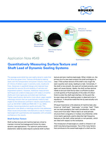
White Light InterferometryAs early as 2002, the Dana Corporation initiated a programto understand if optical-based 3D profilometry could beemployed to quantitatively measure surface texture andlead angle.6 The conclusions indicated that white lightinterferometry is the appropriate technology to bring aquantitative capability to the market.White light interferometry, also known as optical profiling,is a well-established technique for non-contact, 3D surfaceroughness and topography measurements. The method’sunique combination of resolution, speed and repeatabilityhas proven ideal for R&D, process development and qualitycontrol in industries ranging from automotive and aerospaceto ophthalmology and orthopedics as well as semiconductorand data storage. Specifically, the automotive industryis using optical profiling for in-situ cylinder boremeasurements, as well as for the characterization of metals,polymers, sensors and more in R&D and QA/QC.An optical profiler is a specialized microscope that utilizesthe properties of light to achieve topography measurementsof surfaces with feature heights from nanometers to severalmillimeters. In an optical profiler, light approaching thesample is split and directed partly at the sample and partlyat a high-quality reference surface. The light reflected fromthese two surfaces is then recombined. Where the sampleis near focus, the light interacts to form a pattern of brightand dark lines that track the surface shape. The microscopeis scanned vertically with respect to the surface such thateach point of the test surface passes through focus. Thelocation of maximum contrast in the bright and dark linesCameraindicates the best focus position for each pixel, and a full 3Dsurface map is generated.The Bruker NPFLEX-LA 3D Surface MetrologySystem for Lead AngleBruker developed the NPFLEX-LA with participation fromseveral industry partners who were interested in a singlecomprehensive system to measure key properties of sealingsurfaces. During the design and verification process, avariety of parts were measured on multiple systems toassess repeatability, reproducibility, linearity, and system-tosystem correlation.Self-Referencing MetrologyDeveloping a quantitative metrology tool that must measurethe lead angle of a shaft to 0 0.05 while allowing formultiple operators and multiple locations dictates that thesystem must be self referencing in some fashion. Theengineers at Bruker’s Nano Surfaces Division have designedthe NPFLEX-LA to be able to measure the lead angleregardless of part alignment.The system is designed such that an operator loads ashaft in a three jaw chuck, defines the measurement areaalong both the length and circumference of the shaft, andspecifies the required number of locations to measure,typically 250 for a plunge ground shaft. At each location,the system measures a best fit to true cylinder and leadangle with respect to the CCD camera. The system alsosimultaneously conducts a Fourier transform of the data todetermine an angular power spectral density of the angleof the marks on the shaft, again with reference to a CCDcamera. These two calculations are subtracted from eachother at every measurement point, to eliminate any off-axisvariation associated with the mounting of the part. Theresult is a lead angle and surface roughness measurementvalue at every point specified in the measurement set-up.A Technique Ideal for Lead Angle rorObjectiveBeam SplitterSampleFigure 3. Standard schematic of an optical interferometer.4A single NPFLEX-LA measurement field of view rangesfrom 0.5mm x 0.5mm up to about 3mm x 3mm. Thisprovides very high lateral resolution, but data is acquiredfrom only a small surface area. Many fields of view areaveraged to produce a single result, reducing the effect oflocal machining variations that can skew both the roughnessand lead angle values. The operator can choose whethersuch measurements should be spread evenly over the entireshaft or only localized near the seal contact region. Typically,250 measurements take approximately 30 minutes tocomplete. Fewer individual scans may be used to increasethroughput, such as for highly uniform surfaces, but for thisresearch 250 measurements were used throughout.Plunge grinding is one of the most common productionprocesses for precision shafts. A series of plunge groundshafts was obtained with designed lead angles from
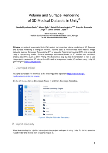
0.5 right hand (RH) to 0.5 left hand (LH) in increments of0.1 degrees for testing. Two additional shafts with 0.05RH and LH leads were also obtained. Shaft diameter wasapproximately 3 inches (76.2mm) and average roughnessapproximately 600nm (23 microinches). Shafts were testedfor lead angle as well as roughness. Results reportedwere the lead angle of the shafts in degrees, and the 3Droughness parameters Sa, Sz, and Spm, which are theequivalents of the 2D roughness parameters Ra, Rz, andRpm. The primary advantage of the 3D parameters is theirinsensitivity to part alignment. Since they calculate overan entire field of view, there is no worry that a single tracewill affect the calculation by not being aligned along theshaft direction. Also, by using an entire field of view, theseparameters are far less sensitive to local part variations.Additional parameters are calculated by the NPFLEX-LA andmay be reported as needed, such as the spatial frequencyof the machining marks, the amplitude of the machiningmarks, and more.Next, system reproducibility was studied. In this test, asingle operator was asked to load and unload the shaftbetween 10 measurement sequences. The starting locationof measurements was not controlled in any way betweenruns to represent an operator randomly approaching thesystem with a part to be tested. In this case, the onesigma standard deviation of lead angle across the runswas 0.02 degrees. This seems mainly driven by variabilityThe first test performed was to determine systemrepeatability. Shafts were mounted on the NPFLEX-LAand the measurement sequence run 30 times withoutremoving or replacing the part. For these shafts, the onesigma standard deviation of the lead angle results wasless 0.005 degrees. The one-sigma standard deviationfor Sa was less than 1.4 nm (0.05 microinches) whilefor Sz and Spm it was 25nm (0.97 microinch) and 18nm(0.72 microinches) respectively.Figure 4. Test shaft mounted on NPFLEX-LA.0.60.70.50.60.50.40.40.30.30.2Sa (um)Lead Angle (deg)Lead Angle and Sa Repeatability0.20.10.10013579 11 13 15 17 19 21 23 25 27 29Measurement NumberChart 1. NPFLEX-LA shows a lead angle static repeatability result better than 0.005 degrees. The green-triangle line represents global leadangle results from 30 measurements. The blue-diamond dataset is the average roughness (Sa) over these same 30 measurements.5
Finally, lead angle results were compared across threedifferent systems. Due to minor imperfections in the opticsused to image samples and the high sensitivity requiredfor lead angle results, all systems are calibrated againstknown lead angle samples so that they will obtain the mostaccurate results possible. Three systems were calibratedthis way and parts of 0.4RH, 0.4LH and 0.05RH lead weremeasured three times each on the three systems, usingseveral different operators. The maximum deviation ofresults between systems was 0.08 degrees for the 0.4degree RH part and was 0.04 degrees for the other twoparts. One sigma standard deviation of results between thesystems ranged from 0.02 to 0.04 degrees. Sa agreed towithin 30nm across all systems with a standard deviation of7nm. Thus, even measuring parts across different systems,using different operators, and not controlling where theparts were measured, agreement between systems isquite good.References1. J. Seewig and T. Hercke. “2nd Generation Lead Measurement.” XIX IMEKOWorld Congress, Sept 2009.2. S.R. Modeling. “Rotary Lip Seals,” Wear 207 (1997) pp. 92-99.3. J. Seewig, T. Hercke. “Lead Characterization by an Objective EvaluationMethod,” Wear 266 (2009) pp. 530-33.4. ISO 6194: 2009 (E). Rotary Shaft Lip-Type Seals Incorporating ElastomericSealing Elements.5. RMA OS-1-1. Rev. 2004. Oil Seal Technical Bulletin Shaft Requirements forRotary Lip Seals6. M. Shuster, D. Combs, J. Pillar, D. Burke, and D. Cohen. “Development ofthe Methodology for 3-D Characterization of Oil Seal Shaft Surfaces.” SAE2002 World Congress.AuthorsDonald K. Cohen, Michigan Metrology (doncohen@michmet.com)Stanley Smith (stanobles@aol.com)Erik L. Novak, Bruker Nano Surfaces Division, Stylus and Optical Metrology(erik.novak@bruker-nano.com)Andrew T. Masters, Bruker Nano Surfaces sBruker’s NPFLEX-LA measurement system providescomprehensive quantification of critical shaft parameters.This non-contact measurement system can handleshafts from 38 to 203mm (1.5 to 8 inches) diameter andreports lead angle and all critical roughness parametersBruker Nano Surfaces DivisionTucson, AZ · USA 1.520.741.1044 ext. 3/800.366.9956 ext.3productinfo@bruker-nano.com6www.bruker.com 2011 Bruker Corporation. All rights reserved. NPFLEX-LA and Vision are trademarks of Bruker Corporation. AN549, Rev. A0.of the part itself, because when the starting position wasroughly controlled, standard deviation dropped to between0.005 and 0.008 degrees, depending on the specific partmeasured. The one sigma standard deviation of Sa, Sz, andSpm were 1.2nm (0.05 microinches), 76nm (3 microinches)and 38nm (1.5 microinches) respectively.Bruker Nano Surfaces Division is continually improving its products and reserves the right to change specifications without notice.Figure 5. NPFLEX-LA is designed such that operators do not have tobe concerned with perfect part level or wobble during mounting.for each measurement. Unlike the string method, whereincreasing lead means fewer shaft rotations and lessresolution, measurement accuracy is not affected by theamount of lead present. Also, the NPFLEX-LA has beenproven to accurately measure leads on ground shafts withlead of 0.05 degrees and less, where the string methodenc
a stylus, or contact profilometer. While stylus profilometers are indeed useful, there are limitations in measuring surface . An optical profiler is a specialized microscope that utilizes the properties of light to achieve topography measurements . T