Transcription
Application NoteIssue DateHot Water System – BoilerJuly 19, 2010Hot Water System—Boiler ControllerApplication NoteApplication Note - Hot Water System-Boiler Controller .4Introduction . 4Related Documentation. 7Control Strategies. 8System Start Determination . 8System Pump Control . 8System Pump Types . 8Lead Pump Identity Determination. 9System Pump Sequencing:. 9System Water Flow Proof . 10Temperature Control . 11Process Variable Determination. 11Setpoint Determination. 11Controlled Devices . 12On/Off Boiler Sequencing . 14Modulating Boiler Sequencing . 15On/Off Boiler with Mixing Valve Sequencing. 16Boiler Pump Operation. 17Boiler Water Flow Proof . 17Isolation Valve Operation . 18Isolation Valve Status. 18Combustion Damper Operation . 18Combustion Damper Status . 19Emergency Power Off . 19Boiler Status. 19Boiler Alarm Status . 20PID Tuning . 20Integral Time . 20Proportional Band . 20FX Builder Application Wizard Concepts . 21Installing the HWS-BLR application Package . 21 2010 Johnson Controls, Inc.Code No. LIT-12011624www.johnsoncontrols.com
Selecting the Boiler System Application Template. 23Configuring the HWS-BLR Application. 24Configuring the Control Strategy. 24Adjusting Setpoints . 27Adjusting Parameters. 28PID Parameters. 29Viewing the Configuration Summary. 30Selecting the User Interface(s) and Supervisor Interface . 31Selecting the Target Device . 31Selecting the Target Device . 32Configuring the Hardware I/Os. 33Generating the Application Files and Documentation . 35Viewing Generated Application and Documentation Files . 36Reviewing an Exported Application File. 36FX CommPro Concepts. 38User Interface Concepts. 38Medium User Interface. 38Medium User Interface Capabilities . 39Medium User Interface Navigation . 39Config Folder. 40Boiler Folders . 40HW System Folder . 43Main Pumps Folder . 43Setpoints Folder . 44Parameters Folder . 45PID Parameters Folder . 45Runtime Folder. 46MUI Status LEDs. 46Accessing a Folder in the MUI . 46Changing a Configuration Setting, Setpoint, or Parameter in the MUI. 46LCD2x4 User Interface. 47LCD2x4 User Interface Capabilities . 47LCD2x4 User Interface Navigation. 48Config Page . 49Boiler Pages. 50HW System Page. 54Main Pumps Page. 55Setpoints Page. 56Parameters Page . 57PID Parameters Page . 58Runtime Page . 59FX Setup Page. 602 Hot Water System—Boiler Controller Application Note
Events Page. 60Graphical Status Icons . 60Accessing a Page in the LCD2x4 UI . 60Changing a Configuration Setting, Setpoint, or Parameter in the LCD2x4 UI. 61Supervisor Interface . 62Hot Water System—Boiler Controller Application Note3
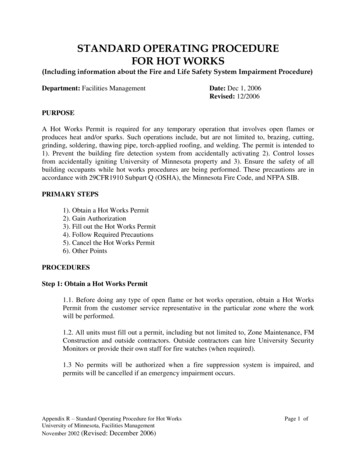
Hot Water System-BoilerController Application NoteIntroductionThis application note introduces the standard Hot Water System-Boiler(HWS-BLR) application template, provides procedures to configure theapplication using FX Builder’s Application Wizard, and explains how tocommission the system using the Integral and Medium User Interface andFX CommPro.The HWS-BLR application template consists of a single applicationsoftware file, which includes multiple configuration options and controlstrategies for controlling many different types of Boiler Systems. Use FXBuilder’s Application Wizard to select the specific configuration optionsand control strategies for your specific heating system controlrequirements.The allowable HWS-BLR configuration options appear in Table 1. Othercontrol strategy and configuration selection options appear in Table 15 –Table 17.4 Hot Water System—Boiler Controller Application Note
Table 1: HWS-BLR Control Strategy and Configuration OptionsConfiguration SettingsAllowable OptionsSystem TypeOn/Off BoilerModulating BoilerOn/Off Boiler with Mixing ValveQuantityOneTwoThreeFourBoiler Sequence TypeFirst-In Last-OutEqual RuntimeEqual StartupBoiler Pump ControlNoYesBoiler Pump StatusNoYesBoiler Pump Alarm SetupAutomatic ResetManual ResetIsolation Valve ControlNoYesIsolation Valve StatusNoYesCombustion Damper ControlNoneOneOne Per BoilerHot Water Control VariableNoYesHW Control VariableReturn TempSupply TempPump TypeNoneConstant VolumeVariable VolumeBypass Differential Pressure ControlPump QuantityNoneOneTwoLead Pump Selection StrategyEqual RuntimeManual Lead SelectPump StatusNoYesPump Alarm SetupAutomatic ResetManual ResetContinued on next page . . .Hot Water System—Boiler Controller Application Note5
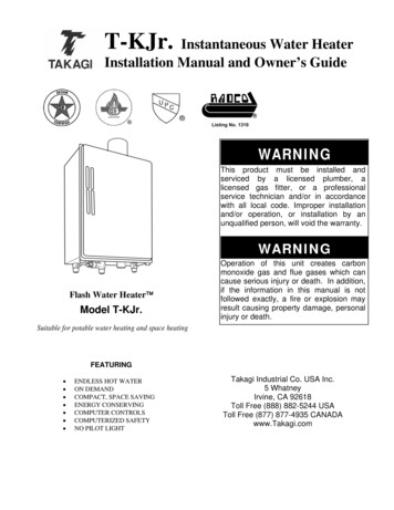
Configuration Settings (Cont.)Allowable OptionsLead Pump SelectionPump1Pump2Emergency Power Off StatusNoYesBoiler Status SetupNoYesBoiler Alarm SetupNoYesFigure 1: Facility Explorer Boiler Application Architecture6 Hot Water System—Boiler Controller Application Note
Related DocumentationTable 2: Related DocumentationFor Information OnSee DocumentLIT or Part NumberFX06 Overview InformationFX06 Field ControllerProduct BulletinLIT-12011165FX06 Technical InformationFX06 Field ControllerTechnical BulletinLIT-12011166FX07 Overview InformationFX07 Field ControllerProduct BulletinLIT-12011268FX07 Technical InformationFX07 Field ControllerTechnical BulletinLIT-12011269FX14 Overview InformationFX14 Field ControllerProduct BulletinLIT-12011163FX14 Technical InformationFX14 Field ControllerTechnical BulletinLIT-12011164FX15 Overview InformationFX15 Field ControllerProduct BulletinLIT-12011082FX15 Technical InformationFX15 Controller TechnicalBulletinLIT-12011107FX16 Overview InformationFX16 Master ControllerProduct BulletinLIT-12011084FX16 Technical InformationFX16 Master ControllerTechnical BulletinLIT-12011108Network Room ModuleOverview InformationNetwork Room ModuleProduct BulletinLIT-12011257Network Room ModuleTechnical InformationNetwork Room ModuleTechnical BulletinLIT-12011258Using the ApplicationWizardFX Tools SoftwarePackage – FX BuilderUser’s GuideLIT-12011154Downloading andCommissioningFX Tools SoftwarePackage – FX CommProN2 User’s GuideLIT-12011152FX Tools SoftwarePackage – FX CommProBACnet User GuideLIT-12011240Hot Water System—Boiler Controller Application Note7
Control StrategiesThe HWS-BLR application is configurable, allowing you to choosecontrol options as needed for your specific application requirements.System Start DeterminationThe HWS-BLR enables the system when the outside air temperature fallsbelow the System Enable setpoint. Alternatively, the HWS-BLRapplication enables the system from a network command, with thenetwork command having priority.When the system is enabled, the HWS-BLR application operates thesystem pumps and boilers according to their control sequence.System Pump ControlSystem pumps control the hot water supply flow to the system loop.System Pump TypesThe HWS-BLR application supports the following three types of systempump types: Constant Volume: when you select this option, the HWS-BLRapplication provides binary (on/off) outputs to start/stop up to twosystem pumps. Variable Volume: when you select this option, the HWS-BLRapplication provides binary (on/off) and analog (modulating) outputsto start/stop up to two system pumps and to proportionally modulatetheir corresponding variable speed drives to satisfy the supply waterdifferential pressure setpoint. Bypass Differential Pressure Control: when you select this option,the HWS-BLR application provides binary (on/off) outputs tostart/stop up to two system pumps and an analog (modulating) outputto proportionally modulate a bypass valve to satisfy the supply waterdifferential pressure setpoint. None: when you select this option, the HWS-BLR application doesnot provide any outputs for system pump control.8 Hot Water System—Boiler Controller Application Note
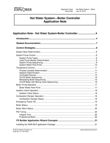
Lead Pump Identity DeterminationThe HWS-BLR application supports one or two system pumps. When twopumps are selected, the HWS-BLR application provides the following twooptions to determine the lead pump identity: Equal Runtime: when you select this option, the HWS-BLRapplication identifies the pump with the lowest runtime as the leadpump. Manual: when you select this option, the HWS-BLR applicationidentifies the pump which is manually selected (via a configurationparameter) as the lead pump.System Pump SequencingThe actual sequencing of system pumps depend on the system pump type(constant volume, variable volume, or bypass differential control) youselect.System Pump Operation—Constant VolumeWhen the system is enabled, the HWS-BLR application starts the leadsystem pump, and it remains energized until the system is disabled. Thesecond pump is not started during this cycle unless a pump status alarm isgenerated. See section System Water Flow Proof for more details.System Pump Operation—Variable VolumeWhen the system is enabled, the HWS-BLR application starts the leadsystem pump, and it remains energized until the system is disabled. TheHWS-BLR application uses a Proportional plus Integral plus Derivative(PID) controller (comparing the actual value of the system water pressureto its setpoint) to determine: the speed of the lead pump’s variable speed drive whether or not to add the second pump the speed of the second pump’s variable speed driveAs the PID controller output rises between 0 and 50%, the HWS-BLRapplication increases the speed of the lead pump from minimum to fullspeed. When the PID controller output reaches 50%, the HWS-BLRapplication starts the second pump. As the PID controller output risesbetween 50 and 100%, the HWS-BLR application increases the speed ofthe second pump from minimum to full speed. See Figure 2 and Figure 3.Hot Water System—Boiler Controller Application Note9
Figure 2: System Pump Operation Example 1Figure 3: System Pump Operation Example 2System Pump Operation—Bypass Differential ControlWhen the system is enabled, the HWS-BLR application starts the leadpump, and it remains energized until the system is disabled. TheHWS-BLR application uses a PID controller (comparing the actual valueof the system water pressure to its setpoint) to determine the proper bypassvalve position to achieve the pressure setpoint.System Water Flow ProofThe HWS-BLR application supports an optional feature to monitor theactual status of the system pumps. When you select this option, theHWS-BLR application provides one binary input for each system pump tomonitor its actual status (as determined by an external flow switch). TheHWS-BLR application compares the actual system pump status to itscommand and operates according to the states shown in Table 3.10 Hot Water System—Boiler Controller Application Note
Table 3: No Water FlowStateDescriptionNormalThe HWS-BLR application enters this state when the pump behaviormatches the pump command.The HWS-BLR application enters this state because there is no proofof water flow and the unit requires manual intervention to restart. Inthis state, the lead system pump remains energized, and if more thanone system pump is selected, then the application starts the secondpump. An alarm output is generated in this state.The HWS-BLR application enters this state because there is no proofof water flow and the unit does not require manual intervention torestart. In this state, the lead system pump remains energized, and ifmore than one system pump is selected, then the application starts thesecond pump. An alarm output is generated in this state.ManualReset FaultSelf ResetFaultTemperature ControlThe HWS-BLR application sequences the boilers to control the processvariable to satisfy a setpoint.Process Variable DeterminationThe HWS-BLR application supports the following two options for theboiler staging process variable: Return Water Temperature: when you select this option, theHWS-BLR application uses the return water temperature as its controlprocess variable. Note: this option is not applicable in a mixing valveapplication. Supply Water Temperature: when you select this option, theHWS-BLR application uses the supply water temperature as its controlprocess variable.Setpoint DeterminationThe HWS-BLR application supports the following two options for theboiler staging setpoint: Fixed Setpoint: when you select this option, the HWS-BLRapplication stages the boilers to satisfy a constant setpoint. Thissetpoint is a user-adjustable parameter. Reset Setpoint: when you select this option, the HWS-BLRapplication calculates the boiler staging setpoint using an outside airreset schedule. The reset calculation parameters (Figure 4) areuser-adjustable.Hot Water System—Boiler Controller Application Note11
Figure 4: Hot Water Temperature Reset by Outside Air TemperatureControlled DevicesThe HWS-BLR application supports the following three types ofcontrolled devices: On/Off Boiler: when you select this option, the HWS-BLRapplication provides binary (on/off) outputs to start/stop up to fourboilers (or boiler stages). The application uses the output of a PIDcontroller (comparing the actual value of the hot water temperature toits setpoint) to add/remove boiler stages according to the boiler stagingtype. Modulating Boiler: when you select this option the HWS-BLRapplication provides binary (on/off) and analog outputs to start/stopand modulate up to four boilers (or boiler stages). The application usesthe output of a PID controller (comparing the actual value of the hotwater temperature to its setpoint) to modulate the boiler output fromminimum output to 100%. The application adds or removes stages ofboilers as needed, according to the boiler staging type. On/Off Boiler with Mixing Valve: when you select this option, theHWS-BLR application provides binary (on/off) outputs to start/stop upto four boilers (or boiler stages) and one analog output toproportionally modulate a mixing valve. The application uses theoutput of a PID controller (comparing the actual value of the boilerloop water temperature to its setpoint) to add/remove boiler stagesaccording to the boiler staging type. The output of a second PIDcontroller (comparing the actual value of the hot water supplytemperature to its setpoint) is used to modulate the mixing valve.The HWS-BLR application supports the following three methods forsequencing the boiler stages.12 Hot Water System—Boiler Controller Application Note
First On/Last Off: when you select this option, Boiler 1 is always thelead boiler. The HWS-BLR application turns additional boilers stageson/off based on first on/last off sequencing. See Table 4 and Table 5.Table 4: First On/Last Off Operation (Increasing PID Output)Stage0%PID Output Increasing100%Stage 1OffOnOnOnOnStage 2OffOffOnOnOnStage 3OffOffOffOnOnStage 4OffOffOffOffOnTable 5: First On/Last Off Operation (Decreasing PID Output)Stage100%PID Output DecreasingStage 1OnOnOnOnOffStage 2OnOnOnOffOffStage 3OnOnOffOffOffStage 4OnOffOffOffOff 0%Equal Runtime: when you select this option, the HWS-BLRapplication turns boilers on/off based on their runtime. For example,the HWS-BLR application starts the boiler with the least amount ofruntime first (becomes lead), and when an additional boiler is needed,the application adds the boiler with the next least amount of runtime.When boilers are de-staged, the HWS-BLR application removes theboiler with the most runtime first. See Table 6 and Table 7.Table 6: Equal Runtime Operation (Increasing PID Output)StageRuntime0%PID Output Increasing100%Stage 190OffOffOffOnStage 240OffOnOnOnOnStage 365OffOffOffOnOnStage 455OffOffOnOnOnOffTable 7: Equal Runtime Operation (Decreasing PID Output)StageRuntime100%PID Output Decreasing0%Stage 195OnOnOnOffOffStage 2110OnOffOffOffOffStage 399OnOnOffOffOffStage 480OnOnOnONOffHot Water System—Boiler Controller Application Note13
Equal Starts: when you select this option, the HWS-BLR applicationturns stages on/off based on their number of starts. For example, theHWS-BLR application starts the boiler with the least number of startsfirst (it becomes lead), and when an additional boiler is needed, theapplication adds the boiler with the next least number of starts. Duringde-staging, the application removes the boiler with the most starts first.In the event of a tie in the number of starts, the HWS-BLR applicationuses equal runtime to break the tie. See Table 8 and Table 9.Table 8: Equal Starts Operation (Increasing PID Output)StageStarts0%PID Output Increasing100%Stage 17OffOffOffOnOnStage 26OffOffOnOnOnStage 35OffOnOnOnOnStage 48OffOffOffOffOnTable 9: Equal Starts Operation (Decreasing PID Output)StageStartsStage 18Stage 27Stage 36Stage 49100%PID Output OffOffOffOffOn/Off Boiler SequencingThe HWS-BLR application sequences up to four on/off boilers (or boilerstages). The HWS-BLR application uses the output of a PID controller(comparing the actual value of the hot water temperature to its setpoint) todrive the adding and removing of boilers (or boiler stages).As the output of the PID controller increases, the HWS-BLR applicationadds a boiler stage when the following relationship is true:PID Output (Capacity x)The Capacity and Differential depends on the number of stages. SeeTable 10.Table 10: Capacity and Differential Based on Number of BoilersNumber of 25%20%14 Hot Water System—Boiler Controller Application Note
The On/Off boiler sequencing selection supports First On/Last Off, EqualRuntime, and Equal Start modes of operation.Modulating Boiler SequencingThe HWS-BLR application sequences up to four modulating boilers (orboiler stages). The HWS-BLR application uses the output of a PIDcontroller (comparing the actual value of the hot water temperature to itssetpoint) to drive the adding and removing of boilers (or boiler stages).As the output of the PID controller increases, the HWS-BLR applicationadds a boiler stage when the following relationship is true:PID Output (Capacity)See Table 11.Table 11: Capacity and Differential Based on Number of BoilersNumber of 25%20%The Capacity and Differential depends on the number of stages.When a stage is added, its corresponding modulated output is ramped overa 3-minute time period, after which output is released and controlled bythe PID output. See Figure 5 and Figure 6.Figure 5: Modulating Boiler Sequencing Example 1Hot Water System—Boiler Controller Application Note15
Figure 6: Modulating Boiler Sequencing Example 2The modulating boiler sequencing selection supports First On/Last Off,Equal Runtime and Equal Start modes of operation.On/Off Boiler with Mixing Valve SequencingThe HWS-BLR application sequences up to four on/off boilers (or boilerstages) to maintain boiler loop temperature setpoint. The HWS-BLRapplication uses the output of a PID controller (comparing the actual valueof the boiler water loop temperature to its setpoint) to drive the adding andremoving of boilers. This option is typically controlled to a fixed setpointof 180 F (82 C).As the output of the PID controller increases, the HWS-BLR applicationadds a boiler stage when the following relationship is true:PID Output (Capacity x)The Capacity and Differential depends on the number of stages. SeeTable 12.Table 12: Capacity and Differential Based on Number of BoilersNumber of 25%20%A separate PID controller controls the hot water mixing valve to maintainbuilding hot water supply setpoint. Typically this value is derived from anoutside air reset schedule. A separate analog output (with selectablepolarity) is provided for the control of the mixing valve.The On/Off boiler sequencing with Mixing Valve selection supports FirstOn/Last Off, Equal Runtime, and Equal Start modes of operation.16 Hot Water System—Boiler Controller Application Note
Boiler Pump OperationThe HWS-BLR application supports the following options for controllingthe boiler pumps: No: when you select this option, the HWS-BLR application does notprovide any outputs for boiler pump control. Yes: when you select this option, the HWS-BLR application providesone binary (on/off) output per boiler to start or stop the boiler pumps.The application starts the boiler pump 30 seconds after its boiler iscommanded on, and it stops the boiler pump 1 minute after its boiler iscommanded off.Boiler Water Flow ProofThe HWS-BLR application supports an optional feature to monitor theboiler pump’s actual status. When you select this option, the HWS-BLRapplication provides one binary input for each boiler pump to monitor itsactual status (as determined by an external flow switch).The HWS-BLR application compares the actual boiler pump status to itscommand and disables the boiler if flow is not proven. The applicationrestarts the boiler automatically if the flow is proven. If more than oneboiler was selected, the application starts the additional boilers as neededto meet the hot water demand.Table 13: No Boiler Water FlowStateDescriptionNormalThe application enters this state when the boiler pump behaviormatches the boiler pump command.Self ResetFaultThe application enters this state because there is no proof of boilerwater flow. The boiler is disabled. The boiler starts automatically whenproof of flow is established. If more than one boiler was selected, theapplication starts the additional boilers as needed to meet the hotwater demand.Hot Water System—Boiler Controller Application Note17
Isolation Valve OperationThe HWS-BLR application supports the following options for controllingthe isolation valves of boilers: No: when you select this option, the HWS-BLR application does notprovide any outputs for isolation valve control. Yes: when you select this option, the HWS-BLR application providesone binary (on/off) output per boiler to open/close the boiler isolationvalves. The application opens the isolation valve if its boiler iscommanded on. The application closes the isolation valve 1 minuteafter its boiler is commanded off.Isolation Valve StatusThe HWS-BLR application supports an optional feature to monitor theactual status of the isolation valve. When you select this option, theHWS-BLR application provides one binary input for each isolation valveto monitor its actual status (as determined by a valve end switch).The HWS-BLR application compares the actual isolation valve status toits command and disables its boiler if the valve is not proved open. Theapplication starts or restarts the boiler automatically when the isolationvalve proves open. If more than one boiler was selected, the applicationstarts the additional boilers as needed to meet the hot water demand.Combustion Damper OperationThe HWS-BLR application supports the following three options forcontrolling the combustion dampers of boilers: None: when you select this option, the HWS-BLR application doesnot provide any outputs for combustion damper contr
whether or not to add the second pump the speed of the second pump's variable speed drive As the PID controller output rises between 0 and 50%, the HWS-BLR application increases the speed of the lead pump from minimum to full speed. When the PID controller output reaches 50%, the HWS-BLR application starts the second pump.