Transcription
American Residential Deck Railing Design GuideIntended foruse byDesigners &ArchitectsEngineers &ProfessionalInstallers8th Edition UpdatedNov. 2017ProbuiltRailings.com
ProBuilt Design Manual - AMERICAN /3 LIST OF FIGURESFIGURE 1:MAIN ELEMENTS OF GUARDRAIL SYSTEMS . 4FIGURE 2:TYPICAL CROSS-SECTIONS OF COMMON GUARDRAIL ELEMENTS . 8FIGURE 3:ACCEPTABLE GUARDRAIL MOUNTING CONFIGURATIONS . 11FIGURE 4:GUARDRAIL CONFIGURATIONS . 21FIGURE 4A: 42” HIGH ALLOWABLE CONFIGURATIONS TYPE 1A . 22FIGURE 4B: 42” HIGH ALLOWABLE CONFIGURATIONS TYPE 1B . 23FIGURE 4C: 42” HIGH ALLOWABLE CONFIGURATIONS TYPE 2 . 24FIGURE 4D: 42” HIGH ALLOWABLE CONFIGURATIONS TYPE 3A . 25FIGURE 4E: 42” HIGH ALLOWABLE CONFIGURATIONS TYPE 3B . 26FIGURE 4F: 42” HIGH ALLOWABLE CONFIGURATIONS TYPE 4 . 27FIGURE 4G 42” HIGH ALLOWABLE CONFIGURATIONS TYPE 5 . 28FIGURE 4H: 42” HIGH ALLOWABLE CONFIGURATIONS TYPE 6 . 29FIGURE 4I: 42” HIGH ALLOWABLE CONFIGURATIONS TYPE 1C . 30LIST OF TABLESTABLE 1: MECHANICAL PROPERTIES OF ALUMINUM ALLOYS AND ELEMENTS . 6TABLE 2: PHYSICAL PROPERTIES OF COMMON ELEMENTS . 7TABLE 3: PROBUILT TESTING RESULTS . 10PROBUILT – 8th EDITION –2015
ProBuilt Design Manual - AMERICAN /17Computer modelling and analysis based on test results of guardrail systems most accuratelyassimilates top rail load distribution to each of the supporting posts and end conditions. The postmoment capacity is calculated using the section modulus (S) and material yield strength (Fy) oralternatively from analysis of test results. This must exceed the resultant bending moment from theapplied loads or the post spacing is reduced to create an acceptable condition.3.0DESIGN TABLESThe design procedures described in the previous section have been carried out for a wide range of possibleguardrail configurations. The results are summarized in the tables which follow. By knowing the overalldimensions and layout of the guardrail system under design, an acceptable configuration can be selectedusing the tables. For each configuration, the maximum allowable post spacing indicated for thelongest straight run shown is also the maximum allowable post spacing for straight runs exceedingin length what is shown.The design tables are based upon the loading criteria set out in the 2015 International Building Code section1607.8.1 Handrails and guards. The actual load conditions for the guardrail system under design must beidentical to or less than those used in the development of the tables. The tables should not be used for otherapplications where different loading conditions and configurations exist.3.1WIND LOADINGFor glass infill guardrail systems, the structural strength requirements imposed by design windloading may exceed those imposed by specified guardrail design loads. Guardrail design loads (asspecified in the 2015 International Building Code) of 20 plf and 50 plf top rail load are the governingcriteria for 42” (1067 mm) high guardrail system designs when compared to uniform lateral specificwind pressures of not greater than 12.7 psf and 28.7 psf respectively. The respective allowableguardrail configurations provided in figures 4 are all capable of withstanding this uniform lateralspecific wind pressures.The procedure for determining net design wind pressures, pnet, for the components and cladding ofbuilding is provided in subsection 1609.6.4.4.1 Components and Cladding of the 2015 InternationalBuilding Code Section 1609 Wind Loads and Chapter 6 of ASCE 7. Using the code provisions, a12.7 psf (0.61kPa) net design wind pressure is given for the following conditions: Exposure B – Urban and suburban areas, wooded areas or other terrain with numerous closelyspaced obstructions having the size of single-family dwellings or larger. Exposure B shall beassumed unless the site meets the definition of anchor type of exposure.Mean roof height of 30 feet (9.144m) or lessImportant factor of 1.050 sq.ft. (4.645m2) effective wind area85 mile per hour (37.4 m/s) nominal design 3-second gust wind speed.Many residential guardrail conditions fit within these criteria. Consult the 2015 International BuildingCode and local building jurisdictional authorities where other conditions apply for determination ofthe net design wind pressure.PROBUILT – 8th EDITION –2015
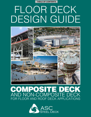
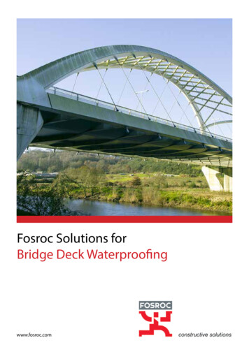
langstruc.tural.eng1neennginc.ProBuilt Design Manual -AMERICANFile No. 112-064December 5, 2017Vista Railing Systems Inc.23282 River RoadMaple Ridge, B.C.Canada V2W 1B6Attention: Mr. Ed GranholmRE:ALUMINUM GUARDRAIL SYSTEMSBUILDING CODE COMPLIANCEAs requested, a series of 42" high allowable guardrail configurations infilledwith %" tempered glass or pickets and acceptable guardrail mountingconfigurations have been determined and are assembled on pages 21 to 30inclusive and pages 11 to 15 inclusive respectively of the ProBuilt AluminumRailings Design Manual - 81h Edition - 2017. These configurations are inconformance with the structural load requirements for balcony guardrails asspecified in the following code: 2015 International Building Code section 1607.8.1 Handrails andguards.The seals applied are current for details and tables assembled for the codeindicated above. Annual resealing of these documents is not necessary .Contact us with any further questions concerning this.Yours truly,LANG STRUCTURAL ENGINEERING INC.Bill Louwerse, PEng., StructEng.,BUigPROBUILT- 8TH EDITION- 2017./20
ProBuilt Design Manual -AMERICAN ./20 File No. 112-064 December 5, 2017 Vista Railing Systems Inc. 23282 River Road Maple Ridge, B.C. Canada V2W 1B6 Attention: Mr. Ed Granholm RE: ALUMINUM GUARDRAIL SYSTEMS BUILDING CODE COMPLIANCE As requested, a series of 42" high allowable guardrail configurations infilled with %" tempered glass or pickets and acceptable