Transcription
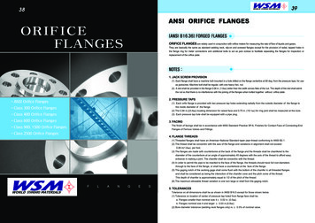
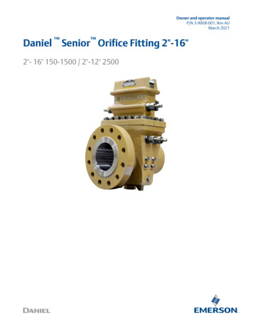
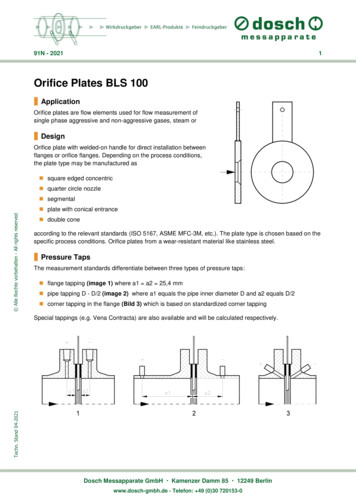
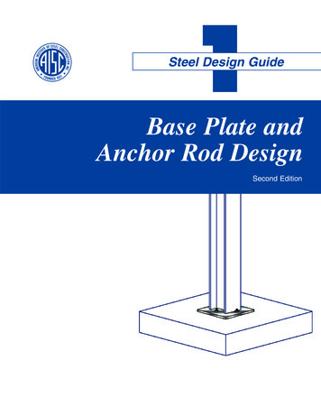
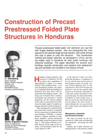
Technical Note1595 2 01 AAJuly 2004Conditioning Orifice PlateConditioning Orifice Plate Technology; Takingthe Standard to a New Level of CapabilityConditioning Orifice Plates, the 1595 Conditioning Orifice Plate and the405C Compact Conditioning Orifice Plate, are differential pressureproducers used to measure rate of fluid flow in a pipe. ConditioningOrifice Plate Technology is based on the same Bernoulli streamlineenergy equation and as a result follows the same Discharge Coefficientversus Reynolds Number relationship as standard orifice plates.Standard orifice plates are typically specified and installed according toone of three standards; AGA Report Number 3, ASME MFC 3M or ISO5167. Although the Conditioning Orifice Plate was designed as closelyas possible to these standards, there are four areas of departure. Thesedifferences allow greater flexibility in installation and better performanceover a wide variety of conditions, including: Superior performance. Installation in short straight pipe run, tight fit applications. Improved performance in wet gas applications by allowingcondensate to pass and preventing the “damming” affectsuffered by standard orifice plates. None of the three standardsprovide allowances for drain vent holes in the orifice plate.The conditioning orifice plate varies from the existing orifice platestandards in four ways: Plate thickness Orifice / Beta Piping Requirements AccuracyFigure 2: 1595 Conditioning Orifice Platewww.rosemount.comFigure 1: 3051SFC ConditioningOrifice FlowmeterFigure 3: Standard Orifice Plate
Technical Note1595 2 01 AAJuly 2004Conditioning Orifice PlateTable 1 depicts a comparison between conditioning orifice plate technology and standard orifice plate technology,highlighting the deviations from the standards. These deviations allow for a more flexible installation as straightpipe requirements are reduced in some cases by as much as 96%.Table 1: The Conditioning Orifice Plate as compared to the orifice plate standards.Category1595 and 405C Conditioning Orifice Plate TechnologyTotal Straight Pipe Run RequirementsUpstream (In Pipe Diameters)Downstream (In Pipe Diameters)1595 and 405C22Flow ConditionersNot Required. All three standards sometimes require flow conditioners to shortenrequired straight pipe run.ASME MFC 3MAGA Report Number 3ISO 5167Up to 545Up to 954.2Up to 607Pressure TapsFlange TapsCorner TapsD and D/2Complies with all three standards.Complies with ASME and ISO. Corner taps not included in AGA Report Number 3.In development.O-Plate Thickness2” to 4”6”8” to 24”Complies with all three Standards.Compliant to ASME MFC 3M and ISO 5167. Thicker than AGA Report Number 3.Complies with all three Standards.BetaArea of 4 holes Area of same ß for standard orifice of all three standards.All other plate dimensions (Includingangle of bevel, bore thickness (e), etc.)Complies with all three Standards.Surface FinishComplies with all three Standards.Discharge Coefficient UncertaintyFollows ISO 5167.Expansion FactorFollows ISO 5167.(1)(2)At Schedule StandardFollows ISO 5167 with a bias shift – The bias is determined in a calibration flow lab andfactored into the DP bore calculation.(2)www.rosemount.com(1)
Technical Note1595 2 01 AAJuly 2004Conditioning Orifice PlatePlate ThicknessTable 2 depicts the plate thicknesses of Conditioning Orifice Plates and the thickness ranges for standard orificeplates as dictated by the three standards. The plate thicknesses for the 1595 and 405C Conditioning OrificePlates fall within the values provided in all three standards with one exception, the AGA Report Number 3standard for the 6” line. In the cases of non-compliance, the important aspect as pertaining to plate thickness isthat the Conditioning Orifice Plates are thicker than the standard orifice plates. This helps prevent plate deflectionunder higher flow rates and leads to a more accurate flow measurement.Table 2: Plate ThicknessASME MFC 3MAGA Report Number 3ISO 51767Line Size1595ConditioningOrifice Plate405CCompactConditioningOrifice PlateMinimumMaximumMinimumMaximumMinimumMaximum2 in(50.8 mm)0.125 in(3.2 mm)0.125 in(6.4 mm)0.120 in(3.1 mm)0.180 in(4.6 mm)0.115 in(2.9 mm)0.130 in(3.3 mm)0.008 in(0.2 mm)0.125 in(3.2 mm)3 in(76.2 mm)0.125 in(3.2 mm)0.125 in(6.4 mm)0.120 in(3.1 mm)0.180 in(4.6 mm)0.115 in(2.9 mm)0.130 in(3.3 mm)0.012 in(0.3 mm)0.158 in(4.0 mm)4 in(101.6 mm)0.125 in(3.2 mm)0.125 in(6.4 mm)0.120 in(3.1 mm)0.180 in(4.6 mm)0.115 in(2.9 mm)0.130 in(3.3 mm)0.017 in(0.4 mm)0.206 in(5.2 mm)6 in(152.4 mm)0.250 in(6.4 mm)0.250 in(6.4 mm)0.120 in(3.1 mm)0.275 in(7.0 mm)0.115 in(2.9 mm)0.192 in(4.9 mm)0.026 in(0.7 mm)0.310 in(7.9 mm)8 in(203.2 mm)0.250 in(6.4 mm)0.250 in(6.4 mm)0.120 in(3.1 mm)0.275 in(7.0 mm)0.115 in(2.9 mm)0.319 in(8.1 mm)0.036 in(0.9 mm)0.413 in(10.5 mm)10 in(254.0 mm)0.250 in(6.4 mm)0.120 in(3.1 mm)0.500 in(12.7 mm)0.115 in(2.9 mm)0.319 in(8.1 mm)0.044 in(1.1 mm)0.520 in(13.2 mm)12 in(304.8 mm)0.250 in(6.4 mm)0.183 in(4.6 mm)0.500 in(12.7 mm)0.175 in(4.4 mm)0.398 in(10.1 mm)0.053 in(1.3 mm)0.620 in(15.8 mm)14 in(355.0 mm)0.350 in(8.9 mm)0.183 in(4.6 mm)0.500 in(12.7 mm)0.175 in(4.4 mm)0.398 in(10.1 mm)0.058 in(1.5 mm)0.683 in(17.3 mm)16 in(406.4 mm)0.350 in(8.9 mm)0.183 in(4.6 mm)0.500 in(12.7 mm)0.175 in(4.4 mm)0.500 in(12.7 mm)0.067 in(1.7 mm)0.783 in(19.9 mm)18 in(457.2 mm)0.350 in(8.9 mm)0.183 in(4.6 mm)0.500 in(12.7 mm)0.175 in(4.4 mm)0.500 in(12.7 mm)0.075 in(1.9 mm)0.883 in(22.4 mm)20 in(508.0 mm)0.350 in(8.9 mm)0.183 in(4.6 mm)0.500 in(12.7 mm)0.240 in(6.1 mm)0.505 in(12.8 mm)0.083 in(2.1 mm)0.984 in(25.0 mm)24 in(609.6 mm)0.500 in(12.7 mm)0.245 in(6.2 mm)0.500 in(12.7 mm)0.240 in(6.1 mm)0.562 in(14.3 mm)0.100 in(2.5 mm)1.184 in(30.1 mm)NOTEThe values that are in Bold reflect the deviation from the standards.www.rosemount.com
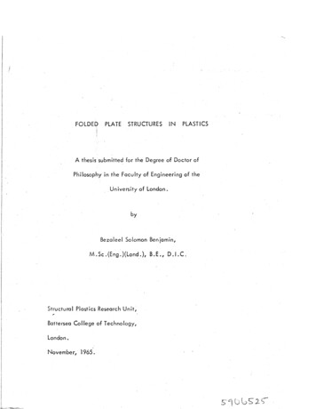
Technical NoteConditioning Orifice Plate1595 2 01 AAJuly 2004Orifice / BetaThe most obvious difference between standard orifice plates and the Conditioning Orifice Plates is four holesversus a single hole. These four holes are placed tangent to the pipe wall, leaving a metal section of the plate inthe center of the pipe. This causes the flow to condition itself as it is forced through the four holes therebyremoving the requirement for a flow conditioner. Because of this phenomenon, Conditioning Orifice Plates providesuperior performance in short straight pipe run and tight fit applications.Standard orifice plates are sized to a beta from 0.1 to 0.75, beta d/D, where “d” is the bore size and “D” is theinternal diameter of the pipe/meter tube. The 1595 and 405C Conditioning Orifice Plates are designed with 2standard bore sizes, one for high flow rates and one for low flow rates. These standard bore sizes are fixed anddo not change with pipe schedule. We refer to the two different bore sizes as betas because the sum of the areaof the four bores is equivalent to the area of a bore “d” in the standard equation “beta d/D” for a schedulestandard pipe. In a schedule standard pipe, the bores equal betas of 0.4 and 0.65. The fixed bores or beta ratiosmake it easier to specify and order while reducing inventory.Also a concern for orifice plate is centering. The orifice must be centered or conditions may arise that negativelyaffect accuracy. The 405C Compact Conditioning Orifice Plate is supplied with a centering ring and assures acentered plate to within 1/32”. If the orifice plate, whether it is a Conditioning Orifice Plate or a standard orificeplate, is not centered, there can be as much as 5% degradation in accuracy.Piping RequirementsStandard orifice plates require significant straight pipe to assure an accurate flow measurement while conditioningplate technology requires only 4 diameters of straight pipe. This equates to significant savings in pipe materialcosts and allows flexibility in determining flowmeter placement. There are dramatic savings to be obtained whenpurchasing pipe, in some cases there is up to a 96% reduction in straight pipe requirements.Figure 4: Conditioning Orifice Plates can reducepiping requirements by as much as 96%Table 3 demonstrates that the 1595 and 405C Conditioning Orifice Plates require just 2 diameters upstream anddownstream. The values in Italics are the reduction in pipe requirements if a Conditioning Orifice Plate is usedinstead of a standard orifice plate. The (Bold) values in the tables reflect the straight pipe requirement if a flowconditioner is installed.www.rosemount.com
Technical Note1595 2 01 AAJuly 2004Conditioning Orifice PlateTable 3: Straight pipe required in pipe diametersUpstreamBeta 0.4ConditioningOrifice PlateASME MFC3MAGA ReportNumber 3ISO 5167Single 90 Degree Bend21486%1688%1688%Single Tee21486%978%978%Two or more Bends in the same plane218 (17)89% (88%)1080%1080%Two or more Bends in a different plane236 (19)94% (89%)50 (29)96% (93%)50 (30)96% 0%3.238%667%ConditioningOrifice PlateASME MFC3MAGA Report(1)Number 3Single 90 Degree Bend22291%44 (29)95% (93%)44 (30)95% (93%)Single Tee22291%44 (29)95% (93%)36 (30)94% (93%)Two or more Bends in the same plane232 (22)94% (91%)44 (29)95% (93%)44 (30)95% (93%)Two or more Bends in a different plane254 (25)96% (92%)95 (29)98% (93%)60 (30)97% (93%)Reducer21283%1182%1283%Valve21688%35 (29)94% (93%)1889%2560%4.248%771%DownstreamUpstreamBeta 0.65Downstream(1)The piping requirements specified are for Beta 0.67.NOTEThe values in Italics reflect the reduction in straight pipe requirements.The values in (Bold) reflect the piping requirements if a 19-tube bundle flow straightener is used.www.rosemount.comISO 5167(1)
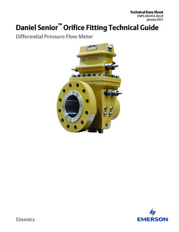
Technical Note1595 2 01 AAJuly 2004Conditioning Orifice PlateAccuracyThe innovative technology and design of the Conditioning Orifice Plate enables multiple benefits withoutcompromising performance. The Conditioning Orifice Plate follows the discharge coefficient of the ISO 51672:2003(E) with a bias. This bias is determined at the time of manufacture and factored into the bore calculation.With just 4 diameters (2 up and 2 down) of straight piping, the discharge coefficient uncertainty (UCd) follows theuncertainty of the standard orifice plate when installed according to the relevant standard. This has been verifiedin independent test laboratories. Results can be found in the Rosemount 405 Compact Orifice Flowmeter Seriesand 1595 Conditioning Orifice Plate Flow Test Data Book and Flow Handbook, part number 00821-0100-4810.Tables 4 - 6 and Equation 1 depict the discharge coefficient uncertainties for all orifice plates according to typicalstandards. Graphs 1 and 2 illustrate the discharge coefficient uncertainties, comparing the standard orifice plates(with sufficient straight pipe run) against the Conditioning Orifice Plate (with 2 diameters of straight pipe runimmediately after a flow disturbance). The end result is that the Conditioning Orifice Plate rivals the performanceof the standard orifice plates while virtually eliminating straight pipe run requirements. With sufficient straight run,the accuracy curve of the Conditioning Orifice Plate would follow the ISO 5167 standard.Table 4: Conditioning Orifice Technology Discharge Coefficient UncertaintyBetaReynolds Number 10,000Reynolds Number 10,0000.4UCd 1.0%UCd 0.5%0.65UCd 1.25%UCd 0.75%Table 5: AMSE MFC-3M – 1989 Discharge Coefficient Uncertainty (Section 7.3.2.1)RD0.2 Beta (β) 0.60.6 Beta (β) 0.7510,000 RD 108UCd 0.60%UCd (β)%UCd (0.6 β)%2,000 RD 10,000Table 6: ISO 5167-2:2003(E) Discharge Coefficient Uncertainty (Section 5.3.3.1)Beta (β)Reynolds Number 10,000Reynolds Number 10,0000.2 β 0.5UCd 0.5%UCd 0.5%0.5 β 0.6UCd 1.0%UCd 0.5%0.6 β 0.75UCd (1.667 * β)%UCd (1.667 * β - 0.5)%Equation 1: AGA Report Number 3 Discharge Coefficient Uncertainty (Section 1.12.4.1 in Part 1)0.8 4000 %UCd 0.5600 0.2550 * β 1.9316 * β * 1 0.7895 * Re D [www.rosemount.com8]
Technical Note1595 2 01 AAJuly 2004Conditioning Orifice PlateGraph 1: Discharge Coefficient Uncertainties for 0.4 BetaDischarge Coefficient UncertaintyBeta 0.41.20%1595 and 405C Conditioning Orifice PlatesASME MFC 3MAGA Report Number 3ISO 010 0000000.00%Reynolds NumberGraph 2: Discharge Coefficient Uncertainties for 0.65 BetaDischarge Coefficient UncertaintyBeta 0.651.40%1595 and 405C Conditioning Orifice PlatesASME MFC 3MAGA Report Number 3ISO 09000010 0000000.00%Reynolds Numberwww.rosemount.com
Technical NoteConditioning Orifice Plate1595 2 01 AAJuly 2004SummaryThe Conditioning Orifice Plate is a revolutionary innovativetechnology based on the most common differential primary elementin the industry. While not complying with the standards of AGAReport Number 3, ASME MFC 3M or ISO 5167, it is designed basedon those standards and provides superior performance in shortstraight pipe run, tight fit applications with upstream flowdisturbances. Requires 2 diameters upstream of a flow disturbance and2 diameters downstream.o Decreased straight runs can lower installed cost.o Provides flexibility of flowmeter placementand design. Compact design reduces installation costs as compared tostandard orifice plates. Highly accurate and repeatable primary elements. Simplified ordering and reduction in inventory, only twobetas to choose; one for high flows, one for low flows. Suitable for most gas, liquid and steam applications.Whether compliance to a standard is required or if it is not required,Emerson Process Management has the flowmeter to fit theapplication.Rosemount and the Rosemount logotype are registered trademarks of Rosemount Inc.All marks are the property of their respective owner
4.2 ISO 5167 Up to 60 7 Flow Conditioners Not Required. All three standards sometimes require flow conditioners to shorten required straight pipe run. Pressure Taps Flange Taps Corner Taps D and D/2 Complies with all three standards. Complies with ASME and ISO. Corner taps not included in AGA Report Number 3. In development. O-Plate Thickness 2” to 4” 6” 8” to 24” Complies with all .