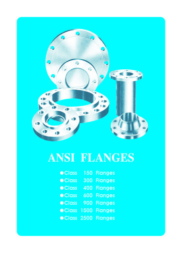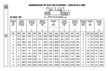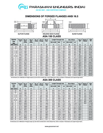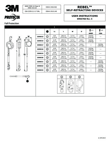
Transcription
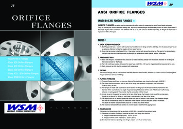
METAL-KOREA3839ANSI ORIFICE FLANGESORIFICEFLANGES(ANSI B16.36) FORGED FLANGESORIFICE FLANGES are widely used in conjunction with orifice meters for measuring the rate of flow of liquids and gases.They are basically the same as standard welding neck, slip-on and screwed flanges except for the provision of radial, tapped holes inthe flange ring for meter connections and additional bolts to act as jack screws to facilitate separating the flanges for inspection orreplacement of the orifice plate.NOTES :1. JACK SCREW PROVISION(1) Each flange shall have a machine bolt mounted in a hole drilled on the flange centerline at 90 deg. from the pressure taps, for useas jackscrew. Machine bolt shall be regular, with one heavy hex. nut.(2) A slot shall be provided in the flange 0.06 in. (1.6 ) wider than the width across flats of the nut. The depth of the slot shall admitthe nut so that there is no interference with the joining of the flanges when bolted together without orifice plate.2. PRESSURE TAPSANSI Orifice Flanges(1) Each orific flange is provided with two pressure tap holes extending radially from the outside diameter of the flange tothe inside diameter of the flange.Class 300 Orifice Flanges(2) The 0.94 in.(23.8 ) locating dimension for raised face and 0.75 in. (19.1 ) for ring joint shall be measured at the bore.Class 400 Orifice Flanges(3) Each pressure tap hole shall be equipped with a pipe plug.Class 600 Orifice Flanges3. FACINGThe finish of facings shall be in accordance with MSS Standard Practice SP-6, Finishes for Contact Face of Connecting-EndClass 900, 1500 Orifice FlangesFlanges of Ferrous Valves and Fittings.Class 2500 Orifice Flanges4. FLANGE THREADS(1) Threaded flanges shall have an American National Standard taper pipe thread conforming to ANSI B2.1.(2) The thread shall be concentric with the axis of the flange and variations in alignment shall not exceed0.06 in(1.6 ). per foot.(3) The flanges are made with counterbores at the back of the flange and the threads shall be chamfered to thediameter of the counterbore at an angle of approximately 45 degrees with the axis of the thread to afford easyentrance in making a joint. The chamfer shall be concentric with the thread.(4) In order to permit the pipe to be inserted to the face of the flange, the threads should have full root diametersthrough to the face of the flange, or shall have a counterbore at the face of the flange.(5) The gaging notch of the working gage shall come flush with the bottom of the chamfer in all threaded flangesand shall be considered as being the intersction of the chamfer cone and the pitch come of the thread.This depth of chamfer is approximately equal to 1/2 of the pitch of the thread.(6) The maximum allowable thread variation is one turn large or shall from the gaging notch.METAL-KOREAFLANGES5. TOLERANCESTolerance on all dimensions shall be as shown in ANSI B16.5 except for those shown below.(1) Tolerance on location of center of pressure tap hole2 from flange face shall be;a. Flanges smaller than nominal size 4 0.02 in. (0.5 )b. Flanges nominal size 4 and larger 0.03 in.(0.8 )(2) Bore diameter tolerance (welding neck flanges only) is 0.5% of nominal value.
METAL-KOREA40METAL-KOREACLASS 300 ORIFICE FLANGES41CLASS 300 ORIFICE FLANGESWELDING NECK (RAISED FACE)SLIP-ON1.6 1.6 THREADED1.6 1.6 1/4” Drill for Sizes 21/2”and Under3/8” Drill for Sizes 3”1/2” Drill for Sizes 4”and Over1/4”Drill for Sizes 21/2”and Under3/8”Drill for Sizes 3”1/2”Drill for Sizes 4”and OverANSI B16.36 FORGED FLANGESofFlangeDiam.THCKNESSOFFLANGE (t)Diam. ofHub atBaseDiam. ofRaisdeFaceDiam. ofHub atBevelWeldingNeckSlip-on zePitchRingDiam. ofNumberRing andGrooveDEPTH OFJACKSCREW 00.153.8154.2170.76211.1R4512.7P9.7Jack screw size for1" thru 24" are those shownfor length and diameter of bolts.OutsideNominalPipeSizeUnit:mmUnit:mmBORE (B)LENGTH THRU HUB (T)DRILLING TEMPLATEDiam. of StudBolts (inch)Diam. ofStud HolesLength ofStud BoltsDiam. ofBolt CircleNumberof 6.024692.2R7731.8812.82411/241.1241.3Notes:(1) For the 'Bore' (B) of welding Neck Flanges other than Standard Wall Thickness, rerfr to page 54.(2) Class 300 Welding Neck Flanges of sizes 24" (609.6 ) and smaller will be bored to match Standard Wall Pipe unless otherwisespecified.(3) Class 300 Orifice flanges will be furnished with 0.06" (1.6 ) raised face, which is included in 'Thickness' (t) and 'Length through Hub' (T).(4) Bolt lengths for raised face flanges include allowance for orifice and gasket thickness of 0.25" (6.4 ) for sizes 4-12 and 0.38" (9.7 ) forsizes 14-24.(5) Unless otherwise specified, unions of 1" (25.4 ) thru 24" (609.6 ) furnished with carbon steel regular square headed bolts withsemifinished American Standard heavy series hex nuts.
METAL-KOREA42METAL-KOREACLASS 400 ORIFICE FLANGES43CLASS 400 ORIFICE FLANGESWELDING NECK (RAISED FACE)WELDING NECK (RING-TYPE JOINT)NPS 3”:1.6 NPS 4”:6.4 1/4” Drill for Sizes 21/2”and Under1/4” Drill for Sizes 21/2”and Under3/8” Drill for Sizes 3”3/8” Drill for Sizes 3”1/2” Drill for Sizes 4”and Over1/2” Drill for Sizes 4”and OverANSI B16.36 FORGED KNESSOFFLANGE (t)RaisedFaceRingJoint38.131.8Diam. ofHub atBaseDiam. ofRaisdeFaceUnit:mmUnit:mmDiam. ofHub atBevelLENGTH THRU HUB (T)Welding NeckBORE (B)Slip-on & ThreadedWeldingNeckNominalPipeSizePitchDiam. ofRing 150.8R16DEPTH OF JACKSCREW SLOTJACKSCREW SIZEDRILLING nt(inch)Diam. ofBoltsCircleNoumberofBoltsDiam. ofStudBolts(inch)Diam. ofBoltsHoles9.76.45/8 4.005/8 4.7588.945/8PLength ofStud 3.563.542.284.177.746.039.611/460.3R189.76.45/8 4.005/8 8.385.979.247.841.149.511/268.3R2012.76.43/4 4.253/4 585.979.249.342.962.0282.6R239.76.45/8 4.005/8 .673.288.982.650.844.574.721/2101.6R2612.76.43/4 4.253/4 8.988.982.652.346.090.73123.8R3112.76.43/4 4.253/4 4 3.003/4 4 3.003/4 4.00235.087/825.4146.1158.8170.76211.1R4512.722.41 3.501 .2See Note(1)To be specifie by purchaser11/443.2221.58269.9R4912.722.41 3.501 4.50330.212128.4171.5184.2276.410323.9R5312.722.41 4.001 .41 4.001 .41 4.251 2.4--410.516469.9R6512.722.41 4.251 .4457.2165.1165.1--461.818533.4R6912.722.41 4.501 .2508.0168.1168.1--513.120584.2R7312.722.41 4.751 2.41 5.001 .2609.6174.8174.8-Notes:(1) For the inside diameter of pipes (corresponding to 'Bore' (B) of Welding Neck Flanges), refer to page 54.(2) Class 400 flanges of sizes 3" (76.2 ) and smaller with be furnished with 0.06" (1.6 ) raised face, which is included in "Thickness' (t)and 'Length through Hub' (T).The 0.25"(6.35 ) raised face for sizes 4" (101.6 ) and larger is not included in (t) and (T).(3) Each union includes two carbon steel jack screw bolts with hex nuts.(4) Unless otherwise specified, raised face unions are furnished with alloy bolt studs per ASTM A193 Grade B7 with American standard heavyseries hex. nuts ASTM A194 Class 2H.(5) On ring joint flanges having a groove depth 0.375" (9.5 ) and less, the distance from the center line of the tap hole to the flange face is0.750" (19.1 ). When the depth of groove is 0.438" (11.1 ) or greater, changes in drill size or method of drilling are necessary.(6) Bolt lengths for raised face flanges include allowance for orifice and gasket thickness of 0.25" (6.4 ) for sizes 4-12 and 0.38" (9.7 ) for sizes14-24. Bolt lengths for ring type joint flanges include allowance of 0.62" (15.7 ) for sizes 4-10, 0.75" (19.1 ) for sizes 12-18 and 0.88" (22.4 )for size 20.
METAL-KOREA44METAL-KOREACLASS 600 ORIFICE FLANGES45CLASS 600 ORIFICE FLANGESWELDING NECK (RAISED FACE)WELDING NECK (RING-TYPE JOINT)NPS 3”:1.6 NPS 4”:6.4 1/4” Drill for Sizes 21/2”and Under1/4” Drill for Sizes 21/2”and Under3/8” Drill for Sizes 3”3/8” Drill for Sizes 3”1/2” Drill for Sizes 4”and Over1/2” Drill for Sizes 4”and OverANSI B16.36 FORGED KNESSOFFLANGE (t)RaisedFace38.1RingJoint31.8Diam. ofHub atBaseDiam. ofRaisdeFaceUnit:mmUnit:mmDiam. ofHub atBevelLENGTH THRU HUB (T)Welding NeckBORE (B)Slip-on & H OF JACKRingDiam. ofSCREW SLOTNoumberRing 5150.8R16RaisedFace(inch)RingJoint(inch)6.45/8 4.005/8 4.75P9.7JACKSCREW SIZEDRILLING TEMPLATEDiam. of Noumber Diam. ofStudBoltsofBoltsCircleBolts(inch)Diam. of BoltsHolesLength ofStud .3R189.76.45/8 4.005/8 8.385.979.247.841.149.511/268.3R2012.76.43/4 4.253/4 960.585.979.249.342.962.0282.6R239.76.45/8 4.005/8 /4 4.253/4 7.088.988.982.652.346.090.73123.8R3112.76.43/4 4.253/4 5.73/4 3.003/4 5.73/4 3.503/4 41 3.501 5.985.9See Note(1)To be specifie by purchaser11/443.2221.58269.9R4912.722.41 4.001 .722.41 4.001 .722.41 4.001 .41 5.001 .8177.8---16469.9R6512.722.41 5.001 1533.4457.2184.2184.2---18533.4R6912.722.41 5.001 .6584.2508.0190.5190.5---20584.2R7312.722.41 6.001 2.41 6.001 7.6692.2609.6203.2203.2-Notes:(1) For the inside diameter of pipes (corresponding to 'Bore' (B) of Welding Neck Flanges), refer to page 54.(2) Class 600 flanges of sizes 3" (76.2 ) and smaller with be furnished with 0.06" (1.6 ) raised face, which is included in "Thickness' (t) and'Length through Hub' (T). The 0.25"(6.4 ) raised face for sizes 4" (101.6 ) and larger is not included in (t) and (T).(3) Each union includes two carbon steel jack screw bolts with hex nuts.(4) Bolt lengths for raised face flanges include for orifice and gasket thickness of 0.25" (6.4 ) for sizes 4-12 and 0.38" (9.7 ) for sizes 14-24. Boltlengths for ring type joint flanges include allowance of 0.62" (15.7 ) for sizes 4-10, 0.75" (19.1 ) for sizes 12-18 and 0.88" (22.4 ) for size 20.(5) Unless otherwise specified, raised face unions are furnished with alloy bolt studs per ASTM A193 Grade B7 with American standard heavyseries hex. nuts ASTM A194 Class 2H.(6) On ring joint flanges having a groove depth 0.375" (9.5 ) and less, the center line of the tap hole to the flange face is0.750" (19.1 ). When the depth of groove is 0.438" (11.1 ) or greater, changes in drill size or method of drilling are necessary.
METAL-KOREA46METAL-KOREA47CLASS 900-1500 ORIFICE FLANGESCLASS 900-1500 ORIFICE FLANGESWELDING NECK(RAISED FACE)WELDING NECK(RING-TYPE JOINT)6.35 1/4” Drill for Sizes 21/2”and Unde
The finish of facings shall be in accordance with MSS Standard Practice SP-6, Finishes for Contact Face of Connecting-End Flanges of Ferrous Valves and Fittings. 4. FLANGE THREADS (1) Threaded flanges shall have an American National Standard taper pipe thread conforming to ANSI B2.1. (2) The thread shall be concentric with the axis of the flange and variations in alignment shall not exceed 0 .