Transcription
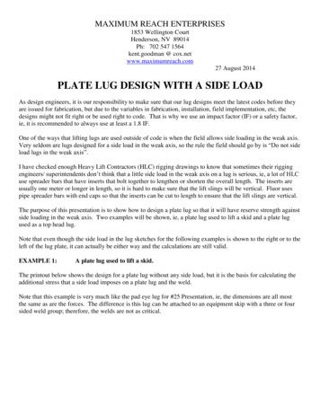
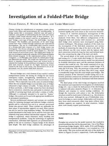
8TRANSPORTATION RESEARCH RECORD 1371Investigation of a Folded-Plate BridgeFOUAD FANOUS,F. WAYNE KLAIBER, AND TAHER MERCHANTClosing a bridge for rehabilitation or emergency repairs alwayscauses costly delays and inconveniences the traveling public. Abridge system that is economical, relatively easy and quick toconstruct, and capable of withstanding the live loads and volumeof today's traffic would alleviate some of these problems. As apossible solution to the nation's need for an emergency or "bypass" bridge, a new type of bridge-the shell bridge-has beendeveloped. The feasibility and practicality of the shell bridgesystem have been verified through analytical and experimentalinvestigations. The use of a folded-plate deck structure insteadof a circular-shell deck structure in a shell bridge system wasinvestigated. The obvious advantage of using a folded-plate crosssection is that fabrication would be much simpler (i.e., flat formwork instead of curved form work). The folded-plate bridge system was investigated analytically using the AN SYS general-purposefinite-element program. In the experimental portion of the investigation, a 1:24 Plexiglas scale model of a folded-plate bridgewas fabricated and tested. The model was subjected to in-planeforces to simulate posttensioning forces and vertical forces tosimulate live loading. In this preliminary investigation, the foldedplate deck structure, except for the higher transverse stressescaused by the lack of arch action, was determined to be an improvement over the circular-shell deck structure.Because bridges are a vital element of any country's surfacetransportation system, the closing of a bridge for any reason(emergency repairs, strengthening, rehabilitation, etc.) always causes costly delays, detours, and inconvenience to thetraveler. This is especially true in the cases of isolated bridgeswhere the next available bridge is several miles away or bridgessubjected to high volumes of traffic. To help alleviate someof these problems, a shell bridge system has been developedthat is economical, relatively easy and quick to construct, andcapable of carrying legal loads and today's volume of traffic.Although it is primarily intended to be used for "bypass"bridges, this system can be used with appropriate modificationin permanent installations.Several prefabricated elements and systems are availabletoday for replacing damaged and deficient bridges relativelyquickly and at a relatively low cost (e.g., precast, prestressedbeams plus precast slabs). These systems are applicable forshort spans; if intermediate supports are used, these systemscan also be used for long multispan bridges. The shell bridgesystem developed in this study can be used for both short andrelatively long spans without intermediate supports. The shellbridge is segmental, which eliminates many handling andtransportation problems. Using the technology of segmentalconstruction, individual shell segments are posttensioned together at the site to construct a bypass bridge of the desiredspan length. The shell bridge combines the advantages ofDepartment of Civil and Construction Engineering, Iowa State University, Ames, Iowa 50011.prefabrication and segmental construction and also has hightorsional rigidity plus arch action in the transverse direction.Fanous et al. reported preliminary investigations of thissystem (1). In their study, 15 different cross sections wereanalyzed. From these, four different configurations of theintegrated deck and circular shell structure (i.e., potentialshell bridge cross sections) were investigated using finiteelement techniques. The primary emphasis of this study wasthe investigation of the shell-deck connection and variousmethods of connecting the edge of the deck to. the shell. Themost efficient was the cross section with the lightest shelldeck connection (relatively long but thin) and inclined members (for connecting the edge of the deck and shell).The second phase of the study involved the constructionand testing of a 1:3 scale model shell bridge (2). The scale ofthe posttensioned reinforced concrete model was determinedby available laboratory space and the minimum thickness ofconcrete that could be cast. The model consisted of six segments posttensioned together to create a model bridge 10 ftwide and 34 ft long. Thus, the prototype of this model wouldbe 30 ft wide (two lanes) and more than 100 ft long, whichis considerably longer than the usual simple span bridges. Theprimary purpose of the laboratory model testing was to determine potential construction problems and potential stressconcentrations that could1not be determined with finite-elementanalysis.The third phase of the shell bridge investigation involvedthe analytical and experimental investigation of a folded-platebridge (3)-one in which the shell portion of the shell bridgeis replaced with plate elements (Figure 1)-to determine itsbehavior and response to various loading conditions. Although the transverse arch action is lost, the folded-platestructure would be much easier to fabricate (e.g., flat elementsin the cross section). Although the use of folded-plate structures for bridges is a new concept, folded-plate roof structureshave been used extensively when long spans without intermediate supports are required. In most situations, foldedplate roofs usually require posttensioning.EXPERIMENTAL PHASEModelPlexiglas was selected for the model material; this resulted inseveral problems that will be discussed later. Use of the PhaseII prototype br'idge (length, 100 ft; width, 30 ft) and Plexiglasthat was readily available (thickness, 1/4 in.) resulted in a 1:24scale model. The cross section and side view of the model areshown in Figures 2a and b, respectively. Curbs and diagonal
9Fanous et al.members were bolted to the model so it could be tested withand without curbs and diagonals.Although the Plexiglas model was fabricated as a unit (i.e.,no individual segments), posttensioning was included becauseit would be required in the prototype. Shown in Figure 2ais the location of the posttensioning applied to the model.Initially, annealed aluminum rods were used for the posttensioning; however, after repeated use, the threads wouldwear out. The aluminum rods were then replaced with steelrods; the higher modulus of elasticity resulted in smaller strainsin the rods, which were obviously more difficult to measureaccurately.(a)Material PropertiesDECKTo determine the modulus of elasticity and Poisson's ratio ofthe Plexiglas, an instrumented simply supported beam, fabricated from the Plexiglas used in the model, was tested usingthird-point loading (2). Midspan transverse and longitudinalstrains were recorded at 15-sec intervals. Results revealed thatthe rate of creep became negligible after a· few minutes. Basedon the test results, instantaneous Young's modulus and Poisson's ratio were determined to be 443,800 lb/in. 2 and 0.36,respectively. After 1 min, Young's modulus of the Plexiglaswas found to be 414,900 lb/in. 2 ; after 2 min it had decreasedto 409,700 lb/in. 2 In the analytical studies, an average mod-(b)FIGURE 1 Shell bridge cross sections: (a) circular-shellelements and (b) folded-plate elements.END DIAPHRAGMBEAMALUMINUM POST-TENSIONING TENDONSSTEEL POST-TENSIONING TENDONSo (a)ANCHOR BLOCKSFOR POST-TENSIONINGTENDONS(b)FIGURE 2 Plexiglas bridge model: (a) cross section of bridge and (b) side view of bridgemodel with six diagonals.
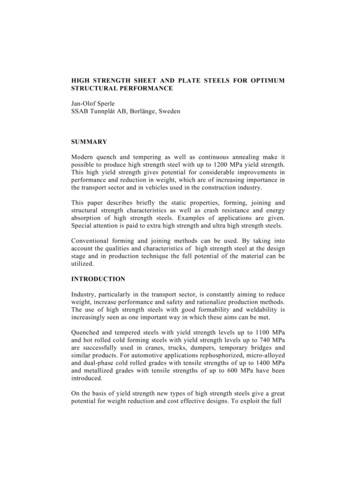
TRANSPORTATION RESEARCH RECORD 137110ulus of elasticity (428,000 lb/in. 2 ) and Poisson's ratio (0.36)were used.(i.e., smallness of model) prevented monitoring the deflections at additional locations.InstrumentationFINITE-ELEMENT ANALYSISBasic instrumentation for the model consisted of electricalresistance strain gauges (henceforth referred to as gauges) formeasuring strains and mechanical dial gauges for measuringdeflections. The gauges were monitored using a computercontrolled data acquisition system.General-purpose temperature-compensate gauges were installed and waterproofed on the model as well as on the posttensioning tendons in accordance with the manufacturer'sguidelines. Two gauges were mounted on each posttensioningtendon longitudinally and diametrically opposite each otherso that the axial force could be measured accurately and bending strains cancelled.Because the model is geometrically symmetric about thelongitudinal and transverse axes, its response under symmetrical loading can be assumed to be symmetric. Takingadvantage of the assumed symmetry, the majority of the gaugeswere installed on one-quarter of the model. However, to verify the assumed symmetric behavior of the bridge, 10 gaugeswere installed on the other quarter-sections of the model.As will be shown, only longitudinal strains in the curbs andbeams are significant; transverse strains are essentially negligible. Hence gauges were positioned so that strains couldbe monitored along the tops and bottoms of the curbs andbeams. Along the longitudinal and transverse centerlines ofthe deck and near the deck-plate connection, two separategauges perpendicular to each other were installed at pointsof interest to measure the longitudinal and transverse strains.This combination was used instead of rosettes to avoid gaugeheating problems. Mechanical dial gauges were used to measure midspan beam· and. curb deflection. Space limitationsModelingThe integrated folded-plate deck bridge model was analyzedusing the ANSYS finite-element program (4). Eight-node solidelements (STIF45 in ANSYS element library) were used toidealize the bridge deck, folded plates, anchor plates, andgusset plates (see Figure 3). These elements were also usedto analyze the shell bridge structures studied in previous related work (1,2). Posttensioning tendons, the. vertical and thediagonal elements connecting the shell edge beam to the deck,were modeled using three-dimensional truss elements (STIFSin ANSYS element library).Because of the geometrical symmetry of the bridge modelabout the longitudinal and transverse axes, only one-quarterof the bridge structure was modeled. Appropriate symmetryand asymmetry boundary conditions were applied at the nodeson the symmetry planes. However, for general cases of loading, four computer runs with various combinations of boundary conditions were needed. For loads symmetric with respectto one of the symmetry planes, only two runs were used. Themodel was analyzed considering the following configurationsand was tested in Configurations 1 and 2. Configuration 1: Model without diagonal members connecting the deck to the folded plate. Configuration 2: Model with six diagonal members connecting the deck to the folded plate. Configuration 3: Model with 12 diagonal members connecting the deck to the folded plate.FIGURE 3 Finite-element model (perspective view) of integratedfolded-plate deck bridge.
Fanous et al.11These differences resulted from the higher creep that occurredin these areas and the way creep was included in the analyticalmodel.PosttensioningIn the finit -element analysis, the posttensioning forces in thetendons were included as a prestrain in the truss elementsused to model the tendons. This was accomplished in stepsto obtain the desired value of posttensioning force in eachtendon. In the first step, the strain in each tendon was estimated using the desired posttensioning forces. However, examination of the analysis results indicated that the forces inthe tendons were slightly less than desired. This lessening ofthe tendon forces was caused by losses in the specified prestrain because of the axial shortening of the bridge caused byposttensioning forces. The prestrain was then modified toaccount for these differences, and the structure was reanalyzed until the desired posttensioning forces were obtained.The final posttensioning forces applied in the analysis wereused in the comparisons with experimental results.Response of the Model Under Single LoadBridge DeckThe deflection of the bridge model deck at mi ;fspan withvarious web member configurations (Figure 2) loaded with asingle load near the curb at midspan is shown in Figure 5.The difference between the measured and theoretical deflections was within 13 percent. Connecting the deck to the foldedplate edge beam reduced the overall deflection and resultedin higher torsional stiffness, as indicated by the smaller differential displacement between Edges A and C shown inFigure 5.The transverse strains across the top of the deck at midspanwhen the load is placed at Points Gl and G3 (Figure 4) areshown in Figure 6. Note the excellent agreement between thefinite-element analysis and the experimental results. Connecting the deck to. the folded-plate edge beam reduced themagnitude of the transverse strains (Figure 6a). These strainswere significantly reduced when the number of the diagonalmembers was doubled (12 diagonals versus 6 diagonals). Increasing the number of diagonals increased the stiffness ofthe cross section and significantly reduced the transverse strainsnear the connection between the folded plate and the deck.On. the other hand, the distribution and magnitude of thetransverse strains in the deck are essentially independent ofthe type of deck-edge beam connection when the load is applied at Point G3 (Figure 6b). The presence of diagonal members improved the overall structural behavior of the sectionunder non-symmetrical loadings.The distribution of the longitudinal strain across the top ofthe deck and along the bridge centerline when the load ispositioned at Point G3 is shown in Figure 7. As can be seen,the strain distribution is not affected by the presence of thediagonal members connecting the deck to the folded plate's.edge beam. Also illustrated in this figure is the overall agreement between the· analytical and experimental results; however, the results differ significantly at the point of loading.This difference most likely results from idealizing the load asa true po
In most situations, folded plate roofs usually require posttensioning. EXPERIMENTAL PHASE Model Plexiglas was selected for the model material; this resulted in several problems that will be discussed later. Use of the Phase II prototype br'idge (length, 100 ft; width, 30 ft) and Plexiglas that was readily available (thickness, 1/4 in.) resulted in a 1 :24 scale model. The cross section and .