Transcription
For Authorized Service Dealers OnlyISUZU N-Series 4HK1 EngineCommon Rail System (CRS) ServiceManualIssued : November 201150000057E
2011 by DENSO CORPORATIONAll rights reserved. This material may not be reproducedor copied, in whole or in part, without the writtenpermission of DENSO Corporation.
Table of ContentsTable of ContentsOperation Section1. Applicable Vehicles and Parts Information1.1Outline . . . . . . . . . . . . . . . . . . . . . . . . . . . . . . . . . . . . . . . . . . . . . . . . . . . . . . . . . . . . . . . . . . . . . . . . . . . . . . . . 1-11.2Applicable Vehicle . . . . . . . . . . . . . . . . . . . . . . . . . . . . . . . . . . . . . . . . . . . . . . . . . . . . . . . . . . . . . . . . . . . . . . . 1-11.3List of Primary Parts . . . . . . . . . . . . . . . . . . . . . . . . . . . . . . . . . . . . . . . . . . . . . . . . . . . . . . . . . . . . . . . . . . . . . 1-22. Common Rail System (CRS)2.1CRS Outline. . . . . . . . . . . . . . . . . . . . . . . . . . . . . . . . . . . . . . . . . . . . . . . . . . . . . . . . . . . . . . . . . . . . . . . . . . . . 1-33. Supply Pump3.1Outline . . . . . . . . . . . . . . . . . . . . . . . . . . . . . . . . . . . . . . . . . . . . . . . . . . . . . . . . . . . . . . . . . . . . . . . . . . . . . . . . 1-43.23.33.44. Rail4.1Outline . . . . . . . . . . . . . . . . . . . . . . . . . . . . . . . . . . . . . . . . . . . . . . . . . . . . . . . . . . . . . . . . . . . . . . . . . . . . . . . . 1-94.2Rail Pressure Sensor. . . . . . . . . . . . . . . . . . . . . . . . . . . . . . . . . . . . . . . . . . . . . . . . . . . . . . . . . . . . . . . . . . . . . 1-94.35. Injectors5.1Outline . . . . . . . . . . . . . . . . . . . . . . . . . . . . . . . . . . . . . . . . . . . . . . . . . . . . . . . . . . . . . . . . . . . . . . . . . . . . . . . 1-116. Control System Parts6.1Engine ECU. . . . . . . . . . . . . . . . . . . . . . . . . . . . . . . . . . . . . . . . . . . . . . . . . . . . . . . . . . . . . . . . . . . . . . . . . . . 1-136.27. Exhaust Gas Treatment System7.1Outline . . . . . . . . . . . . . . . . . . . . . . . . . . . . . . . . . . . . . . . . . . . . . . . . . . . . . . . . . . . . . . . . . . . . . . . . . . . . . . . 1-167.27.38. Diagnostic Trouble Codes (DTC)8.1DTC List. . . . . . . . . . . . . . . . . . . . . . . . . . . . . . . . . . . . . . . . . . . . . . . . . . . . . . . . . . . . . . . . . . . . . . . . . . . . . . 1-219. Control System Component Information9.1Engine ECU Terminal Layout Diagrams . . . . . . . . . . . . . . . . . . . . . . . . . . . . . . . . . . . . . . . . . . . . . . . . . . . . . 1-279.2Connector Diagram . . . . . . . . . . . . . . . . . . . . . . . . . . . . . . . . . . . . . . . . . . . . . . . . . . . . . . . . . . . . . . . . . . . . . 1-29
Table of Contents
Operation Section1– 11. Applicable Vehicles and Parts Information1.1 OutlineAs a result of a model change to the ISUZU 4HK1 engine beginning from May 2010, the Common Rail System (CRS) has also changed. This manual describes items specific to the parts used in the CRS for the4HK1 engine. For CRS basics, refer to the "COMMON RAIL SYSTEM SERVICE MANUAL -OPERATION(Doc ID: 00400534EA)."Compliance with Exhaust Gas RegulationsThe CRS for the 4HK1 engine has undergone the following improvements to comply with US10 exhaust gasregulations.Combustion Improvements System pressure: Increased to 200 MPa Supply pump: Operating pressure of 200 MPa, uses positive pressure system Rail: Operating pressure of 200 MPa Injectors: Uses the G3 typeImproved Post-Processing Particulate Matter (PM) reduction: Diesel Particulate Filter (DPF) NOx Reduction: Urea Selective Catalytic Reduction (SCR)1.2 Applicable VehicleVehicle ManufacturerISUZUVehicle NameEngine TypeExhaust VolumeN SERIES4HK15.2 LProduction StartDateMay 2010
Operation Section1– 21.3 List of Primary PartsDENSO Part Num-Manufacturer PartberNumberSupply 68-0Injector295050-032#8-98110607-2Engine ECU275800-875#8-98160981-2Crankshaft Position Sensor949979-031#8-97606943-0Cylinder Recognition Sensor949979-169#8-98019024-0Fuel Pressure -0DPF Side265600-126#8-98004330-0SCR Side104990-101#8-97359985-2Part NameExhaust Gas Temperature SensorExhaust Gas Temperature SensorDifferential Pressure SensorRemarksHP4 Supply PumpG3 Type
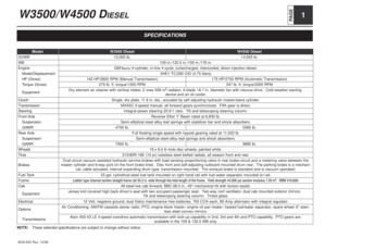
Operation Section1– 32. Common Rail System (CRS)2.1 CRS OutlineThe CRS for the ISUZU 4HK1 engine uses the following fuel flow path to prevent air from mixing with thefuel. The feed pump for the supply pump draws in fuel that is then initially sent to a main filter outside of thesupply pump. Air inside the fuel is released from the air bleed valve on the main filter. Next, the fuel is returned again to the supply pump, and then sent to the rail under high pressure.Fuel TemperatureVehicle SpeedAccelerator PositionBoost PressureIntake Air TemperatureCoolant TemperatureCrankshaft PositionInjectorEngine ECURail Pressure SensorCylinder Recognition SignalPressure LimiterIntake Air MassRailSuction Control Valve(SCV)Supply PumpSub-Filter(Negative Pressure Type)to Fuel AdditionValve (DPF)SuctionAir Bleed ValveFuel Temperature SensorFuel TankMain Filter(Positive Pressure Type)DischargeFeedReturnConventional Supply Pumpto RailSupply PumpFuel FilterFuel TankQ006718E
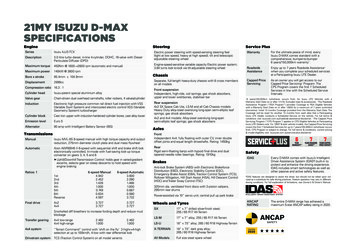
1– 4Operation Section3. Supply Pump3.1 OutlineThe supply pump used with the ISUZU 4HK1 engine is an HP3 type adapted to positive pressure filter use.In comparison to conventional supply pumps, the 4HK1 engine supply pump includes a feed pump outletport, and main filter pump inlet port. Positive pressure is applied to the main filter by sending fuel from thefeed pump to the main filter. In addition, the supply pump uses a normally open SV3 type Suction ControlValve (SCV).Fuel Inlet (from Main Filter)Suction Control Valve (SCV)Suction Control Valve(SCV)Fuel Outlet(Overflow,to Fuel Tank)Fuel Outlet(to Main Filter)Fuel Outlet(Overflow, to Fuel Tank)Supply Pump Adaptedto Positive Pressure Filter UseFuel Inlet(from Sub-Filter)Fuel Temperature SensorFuel InletConventional Supply PumpQ006719E
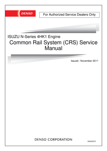
Operation Section1– 5The 4HK1 engine CRS has been adapted to positive pressure filter use to achieve the following effects: Stabilize the fuel supply by placing the fuel filter under positive pressure Suppress filter clogs and increasing filter life Reduce diagnostic abnormalities caused by pressure fluctuations that arise when air intermixing is suppressedRear CoverA rear cover has been added to supply pumps adapted to positive pressure filters since the fuel drawn intothe supply pump is sent to an external main filter. Rear cover construction features the following items: A relief valve to adjust the fuel returning to the supply pump A check valve to increase priming performance to the newly added fuel flow path (i.e., to the main filter)Feed PumpThe feed pump cover and feed pump plate have changed. Moreover, the discharge port on the feed pumpplate is blocked off.Feed Pump PlateDischarge-Side Port ObstructionFeed Pump CoverRear CoverRear CoverRelief ValveCheck ValveQ006720E
1– 6Operation SectionIn a conventional supply pump, fuel is sent directly through the following flow path: feed pumpplunger chamberSCVrail. However, in the supply pump adapted to positive pressure filter use, the fuel flowpath is as follows: feed pumpmain filterSCVplunger chamberrail.Flow Path for Supply Pump Adapted to Positive Pressure Filter UseFlow Path for a Conventional Supply PumpQ004898E
Operation Section1– 7The SCV used with the ISUZU 4HK1 engine is a normally open SV3 type. The SV3 type has the followingfeatures: A more compact design compared to the SV1 type due to a smaller solenoid Improved valve sliding performanceSolenoidValve BodyValve SpringNeedle ValveArmature Cross-Sectional Diagram External View Q006721EPlungerNeedle ValveSupply PumpShort Duty ON DurationLarge Valve OpeningLarge Suction QuantityLarge ValveOpeningCylinderLong Duty ON DurationSmall Valve OpeningSmall Suction QuantitySmall ValveOpeningCylinderQ006722EOperation Concept Diagram
1– 8Operation SectionThe fuel temperature sensor detects the fuel temperature, and sends corresponding signals to the engineECU. The ECU then uses the signal information to calculate an injection correction suited to the fuel temperature. Reference: Temperature/Resistance Characteristics Temperature ()Resistance (k)Fuel Temperature SensorQ006723E
Operation Section1– 94. Rail4.1 OutlineCompared to a conventional rail, the rail used with the ISUZU 4HK1 engine is adapted to high pressure (200MPa). The rail distributes fuel sent from the supply pump to each injector.Fuel InletPressure Limiterto InjectorsRail Pressure SensorQ006724E4.2 Rail Pressure SensorThe rail pressure sensor detects fuel pressure inside the rail. There are two rail pressure sensors to providea backup in case of a malfunction. In addition, the output signal for each sensor system is offset.Rail Pressure (MPa)Q006725E
1– 10Operation SectionThe pressure limiter used with the ISUZU 4HK1 engine is adapted to a pressure of 200 MPa. The pressurelimiter opens to release fuel from the rail when the internal pressure becomes abnormally high. Pressurelimiter construction and characteristics are as shown in the figure below.HousingSpringValveOpen Valveto Fuel Tankfrom RailClosed ValveValve BodyQ004915E
Operation Section1– 115. Injectors5.1 OutlineThe 4HK1 engine CRS uses G3 type injectors. G3 injectors are designed to support a system pressure of200 MPa, to improve responsiveness, and to increase resistance against foreign material adherence to thenozzle.G3 type operation and QR code (ID code) injection quantity corrections are the same as for G2 type withconventional QR codes. (However, the QR code correction points differ.)QR CodeID CodesHigh-Pressure Fuel(from Rail)Solenoid ValveControl ChamberCommand PistonPressure PinNozzle SpringNozzle NeedleQ006726E.
Operation SectionInjection Quantity Q1– 1210 Correction PointsActuation Pulse Width TQQ006727ECorrection Points Using QR Codes
Operation Section1– 136. Control System Parts6.1 Engine ECUThe engine ECU conducts overall engine control. The engine ECU for the ISUZU 4HK1 engine is mountedin the cabin, and contains a built-in injector actuation circuit, thereby eliminating the Electronic Drive Unit(EDU).Q006728
1– 14Operation Section(1) Crankshaft Position Sensor (NE Sensor) and Cylinder Recognition Sensor (G Sensor) The 4HK1 engine CRS uses a crankshaft position sensor (NE sensor) and cylinder recognition sensor (Gsensor). Both sensors are Magnetic Resistance Element (MRE) types.Crank Position Sensor(NE Sensor)Cylinder Recognition Sensor(G Sensor)Q006729ECrankshaft Position SensorThe crankshaft position sensor detects the crankshaft angle. The pulsar has 56 teeth (separated at 6 intervals, with four missing teeth to detect Top Dead Center [TDC] for cylinders no. 1 and no. 4). Circuit Diagram Engine ECUSensorFour Missing TeethNE Input CircuitPulsarQ006730ECylinder Recognition Sensor (G)The cylinder recognition sensor identifies the engine cylinders. The pulsar has five teeth (recognitionof TDC for each cylinder recognition of cylinder no. 1).PulsarsCylinder No. 1Recognition Circuit Diagram Engine ECUSensorG Input CircuitQ006731E
Operation Section1– 15 The 4HK1 engine CRS is equipped with a fuel pressure sensor to detect fuel pressure between the feedpump outlet on the supply pump, and the main filter. Sensor output determines correction control for thefuel addition valve, and whether a main filter clog exists. The fuel pressure sensor is a semiconductor typedevice that uses a characteristic of silicone crystals in which electrical resistance changes when the pressure applied to the crystals is varied.Output Voltage (V)Engine ECUFuel Pressure (MPa)Q006732E(3) Engine Oil Pressure Sensor The engine oil pressure sensor detects engine oil pressure. If engine oil pressure reaches an abnormallyhigh value, the sensor stops the engine.Output Voltage (V)Engine ECUQ006733E
1– 16Operation Section7. Exhaust Gas Treatment System7.1 OutlineThe 4HK1 engine CRS adds a Diesel Particulate Filter (DPF) to eliminate Particulate Matter (PM), and usesurea Selective Catalytic Reduction (SCR) to reduce NOx. Urea SCR adds urea to the exhaust gas, and theSCR catalyst reduces the NOx. The exhaust gas temperature sensor and differential pressure sensor usedin the 4HK1 engine exhaust gas treatment system are made by DENSO.Fuel Addition ValveOxidation CatalystExhaust Gas Temperature SensorDifferential Pressure SensorDPFExhaust Gas Temperature SensorUrea SCR CatalystOxidation CatalystUrea SCRECUUrea Feed DeviceUrea Addition ValveUrea TankQ006734E
Operation SectionPart1– 17FunctionConducts HC and CO purification, as well as NO x oxidation (NO Å NO2).(Adding NO2 promotes NOx reduction.)Diesel Particulate Filter (DPF) Traps PM and conducts PM oxidation treatment.Urea SCR CatalystOxidation Catalyst (Post-UreaSCR Catalyst)ExhaustGasTemperatureSensor (DPF)Uses urea added to the exhaust gas to reduce the NOx.Purifies any urea (ammonia) not used in NOx reduction.Measures the exhaust gas temperature at the DPF, and then outputs corresponding signals to the engine ECU. The engine ECU controls DPF regeneration based on the aforementioned signals.Measures the difference in exhaust gas pressure across the DPF, and thenoutputs corresponding signals to the engine ECU. The engine ECU calcu-Differential Pressure Sensorlates the quantity of PM accumulated in the DPF based on the aforementioned signals, and then determines whether or not to conduct PMregeneration.Mounted upstream of the urea SCR catalyst to measure the NOx concentra-NOx SensorExhaustGastion in the exhaust gas before passing through the catalyst.Temperature Mounted upstream of the urea SCR catalyst to measure the exhaust gasSensor (Urea SCR)temperature before passing through the catalyst.Urea Addition ValveAdds urea to the exhaust gas based on signals from the urea SCR ECU.Urea Feed DeviceDraws urea from the urea tank that is then pumped to the urea additionvalve. The pumping pressure is based on control from the urea SCR ECU.Calculates the optimal urea addition quantity based on signals from the NOxsensor, exhaust gas temperature sensor (urea SCR), etc. Controls the ureaUrea SCR ECUfeed device and urea addition valve so that the optimal amount of urea isadded to the system. In addition, outputs urea SCR system diagnosis to theengine ECU.Exhaust Gas Temperature SensorThe exhaust gas temperature sensor detects the exhaust gas temperature in the vicinity of the catalyst. Athermistor is used for actual temperature detection.Temperature - Resistance Characteristics265600-125#(DPF Side)265600-126#(SCR Side)TemperatureResistance Value*The only difference between the twosensors is the thread pitch.(The specifications are the same.)Q006735E
1– 18Operation SectionThe differential pressure sensor detects the difference in exhaust gas pressure across the DPF. The sensoris a semiconductor type device that uses a characteristic of silicone crystals in which electrical resistancechanges when the pressure applied to the crystals is varied.Engine ECUFuel Pressure (kPa)Q006736E.
Operation Section1– 19The following is an outline of PM regeneration control in the 4HK1 engine CRS. PM regeneration can beperformed both manually and automatically.PM regeneration is normally conducted automatically when the system determines that a set quantity of PMhas accumulated in the DPF. However, there are cases in which PM regeneration does not take place automatically due to driving conditions. When PM is not being regenerated automatically, the following twoindicator lights flash: 1) the light built into the switch for the exhaust gas purification device, and 2) the exhaust gas purification device light located inside the meter panel. These indicator lights are alerts promptingthe user to press the exhaust gas purification device switch and begin manual PM regeneration. When analert occurs, press the exhaust gas purification device switch near the driver's seat to manually start PMregeneration.ControlThe accumulated quantity of PM is inferred from the differential pressure sensor signals (difference in exhaust gas pressure across the DPF). PM regeneration occurs when the accumulated PM quantity is determined to be high (a large differential pressure across the DPF).In PM regeneration mode, after-injection has been added to the normal injection pattern (pre-injection, maininjection). Injection is also performed from the fuel addition valve.The actual control sequence adds the after-injection first to raise the catalyst temperature. Next, when thecatalyst temperature reaches a set value, injection occurs from the fuel addition valve, and full-scale regeneration begins.Regeneration judgments and injection control are conducted by inferring the catalyst temperature base onsignals from the exhaust gas temperature sensors before and after each catalyst.Top Dead Center (TDC)Main InjectionPre-InjectionQ006737E.
1– 20Operation SectionUrea SCR adds an aqueous urea solution to the exhaust gas, and the SCR catalysts reduces the NOx. Theaqueous urea solution is not used as is during NOx reduction. In actuality, the ammonia produced when thesolution undergoes hydrolysis is used to reduce the NOx. A system that contains an aqueous urea solutionis used due to the inherent danger of mounting a source of ammonia directly on the vehicle.The urea SCR ECU controls the urea SCR based primarily on the exhaust gas temperature and the NO xconcentration in the exhaust gas. Ammonia is generated from the aqueous urea solution by using the exhaust gas heat to conduct hydrolysis. As such, the following values are required to add the solution fromthe urea addition valve into the exhaust gas: 1) the quantity of urea that will undergo hydrolysis, calculatedfrom the exhaust gas temperature; and 2) the optimal quantity of solution to be added, calculated from theNOx concentration in the exhaust gas.(1) NOx Reduction Mechanism An oxidation catalyst prior to the urea SCR that initially oxidizes NO into NO2. This catalyst promotes theNOx reduction reaction when NO 2 increases. Adds the aqueous urea solution to the exhaust gas after it has passed through the DPF. The added aqueous urea solution is hydrolysized by exhaust gas heat and converted into ammonia and CO2. Uses the ammonia generated from the aqueous urea solution to reduce and convert the NOx into N2 (nitrogen) and H 2O (water). Purifies any ammonia not used in NO x reduction.Oxidation CatalystNNO Oxidized into NO2Aimed at the NOXreduction reaction (1)in the urea SCR catalyst.DPFUrea Addition ValveAmmonia GenerationUrea SCR CatalystNOX ReductionAn aqueous urea solution is hydrolysized using the exhaust gas heat to generateammonia.Four reduction reactions are triggered in the catalystto reduce the NOX. However, the reaction (1)is the most efficient.Reaction in the Urea SCR CatalystReductionReactionCatalystQ004928E
Operation Section1– 218. Diagnostic Trouble Codes (DTC)8.1 DTC ListDTCDetection ItemP000FRail pressure too lowP0016Crankshaft position-intake camshaft position correlation bank 1P0027Exhaust brake valve stickExhaust throttle valve stickP003AP0045Variable Geometry Turbo (VGT) module wiping too wide errorVGT module motor circuit short and GND short/position control abnormal/power supplyvoltage high errorP0046VGT module control response abnormalP006EVGT module power supply voltage low errorP0079Exhaust throttle GND shortP007CCharge Air Cooler (CAC) out temperature sensor circuit low voltageP007DCAC out temperature sensor circuit high voltageP0080Exhaust throttle B shortP0087Rail pressure low during power enrichmentRail pressure too highP0088Fuel pressure regulator 1 performanceP0089Rail pressure exceeds high upper limitP0091Rail fuel pressure regulator solenoid 1 control circuitP0092Rail fuel pressure regulator solenoid 1 control circuitP0093Rail fuel pressure low during idle or deceleration fuel cut-offP0097Intake manifold temperature sensor 2 circuit lowP0098Intake manifold temperature sensor 2 circuit highP00AFVGT module memory access abnormalMass Air Flow (MAF) meter rationality lowP0101MAF meter rationality highP0102MAF meter circuit lowP0103MAF meter circuit highP0112Intake air temperature sensor circuit lowP0113Intake air temperature sensor circuit highP0116Engine coolant temperature sensor performanceP0117Engine coolant temperature sensor circuit lowP0118Engine coolant temperature sensor circuit highP011CCAC temperature outlet sensor surveillanceP0126Engine coolant temperature insufficient for stable operation
1– 22Operation SectionDTCDetection ItemP0128Engine coolant temperature below thermostat regulating temperatureP0171Injector quantity lean performanceP0172Injector quantity rich performanceP0181Fuel temperature sensor intermediate holdP0182Fuel temperature sensor A circuit lowP0183Fuel temperature sensor A circuit highRail pressure sub-sensor signal keeping the middle rangeP018BRail pressure sub-sensor performance 1Rail pressure sub-sensor performance 2P018CRail pressure sub-sensor circuit low voltageP018DRail pressure sub-sensor circuit high voltageRail pressure sensor signal keeping the middle rangeP0191Rail pressure sensor performance 1Rail pressure sensor performance 2P0192Rail pressure sensor circuit low voltageP0193Rail pressure sensor circuit high voltageP0201TWV 1 output open load injector #1 coil openP0202TWV 4 output open load injector #2 coil openP0203TWV 2 output open load injector #3 coil openP0204TWV 3 output open load injector #4 coil openP020AInjector #1 quantity increase failureInjector #1 quantity decrease failureP020BInjector #2 quantity increase failureInjector #2 quantity decrease failureP020CInjector #3 quantity increase failureInjector #3 quantity decrease failureInjector #4 quantity increase failureP020DInjector #4 quantity decrease failureEngine overrunP0219Engine overrun 2P0234Turbo/supercharger engine overboostP0237Turbo/supercharger boost sensor A circuit lowP0238Turbo/supercharger boost sensor A circuit highP0261Injector #1 (TWV 1) load short (coil short/terminal short)P0264Injector #4 (TWV 4) load short (coil short/terminal short)P0267Injector #2 (TWV 2) load short (coil short/terminal short)P0270Injector #3 (TWV 3) load short (coil short/terminal short)P0299Turbo/supercharger engine underboostP02E2ITHR DC motor output open load motor open load
Operation SectionDTCP02E3Detection ItemITHR DC motor output short to battery/short to GND motor shortIntake throttle stuck closedP02E7Intake throttle stuck openIntake throttle open learning errorIntake throttle closed learning errorP02E8Intake throttle position too lowP02E9Intake throttle position too highP0300Engine misfire detectedP0301Cylinder 1 misfire detectedP0302Cylinder 2 misfire detectedP0303Cylinder 3 misfire detectedP0304Cylinder 4 misfire detectedP0335Crankshaft position sensor A circuitP0336Crankshaft position sensor A performanceP0340Intake camshaft position sensor circuit bank 1P0341Intake camshaft position sensor performance bank 1P0381Wait to start light control module internal circuit (short to BATT)Wait to start light control module internal circuit (open load/short to GND)P0401MAF meter performance (Exhaust Gas Recirculation [EGR] negative deviation)P0402MAF meter performance (EGR positive deviation)EGR duty errorP0403EGR brushless motor circuit too highEGR brushless motor circuit too lowEGR brushless motor circuit too openP0404EGR open position performanceP0405EGR brushless motor position sensor signal invalid lowP0406EGR brushless motor position sensor signal invalid highP040BEGR gas sensor performanceP040CEGR gas temperature too lowP040DEGR gas temperature too highP041BEGR gas sensor 2 performanceP041CEGR gas temperature 2 too lowP041DEGR gas temperature 2 too highP0420DPF deterioration 2P042EEGR closed position performanceP046CEGR closed learningP0500Vehicle speed sensor circuitP0506Low target idle speedP0507High target idle speed1– 23
1– 24Operation SectionDTCDetection ItemP0512Starter switch short to BATTP0522Oil pressure sensor signal too lowP0523Oil pressure sensor signal too highP0545Exhaust gas temperature before oxidation catalyst too lowP0546Exhaust gas temperature before oxidation catalyst too highP0562System low voltage status determinationP0563System high voltage status determinationP0567Cruise control resume switch determinationP0568Cruise control set switch determinationP0571Cruise control brake switch determinationP0602QR code errorP0606Engine ECU processor (main CPU fault)Engine ECU processor (watchdog IC fault)P062FControl module long term memory performanceP0642Battery 5 V reference 1 circuit lowP0643Battery 5 V reference 1 circuit highGlow plug module control circuitP064CGlow plug module INTSTGlow plug module MEEPSTP0650Malfunction Indicator Lamp (MIL) control circuit monitoring (short to BATT)MIL control circuit monitoring (open load/short to GND)P0652Battery 5 V reference 2 circuit lowP0653Battery 5 V reference 2 circuit highP0671Cylinder 1 glow plug circuitP0672Cylinder 2 glow plug circuitP0673Cylinder 3 glow plug circuitP0674Cylinder 4 glow plug circuitP0687Main relay diagnostics; main relay stuck closedP0698Battery 5 V reference 3 circuit lowP0699Battery 5 V reference 3 circuit highP0700Transmission control module requested MIL illumination monitoringP1072Compressor outlet temperature sensor circuit low voltageP1073Compressor outlet temperature sensor circuit high voltageP1076CAC in temperature sensor circuit low voltageP1077CAC in temperature sensor circuit high voltageP1078CAC temperature inlet sensor surveillanceSupply pump protectionP1085P1102Supply pump exchangeRail pressure sensor performance (correlation abnormal)
Operation SectionDTCDetection ItemP1125Accelerator Pedal Position (APP) systemP113AO2 signal of NOx sensor rationalityP1236CAC performanceP1259Rail fuel pressure low during power enrichmentP1261Capacitor charge-up circuit malfunction (insufficient charge)Capacitor charge-up circuit malfunction (excessive charge)P1463DeNOx-DS error for SVS lighting requestP1470DPF exhaust presser performanceP1471DPF regeneration insufficiencyP160BQ DATA cross check errorP2002DPF deterioration (II)P2032Exhaust gas temperature before DPF too lowP2033Exhaust gas temperature before DPF too highP20C9DeNOx-DS error for MIL lighting requestP20CBExhaust injector circuit GND short/open loadP20CCExhaust injector circuit BATT shortExhaust injector circuit load shortP20CFP20DEExhaust injector performanceExhaust injector pressure sensor performance highExhaust injector pressure sensor performance lowP20DFExhaust injector pressure sensor circuit low voltageP20E0Exhaust injector pressure sensor circuit high voltageP20E2Exhaust gas temperature sensor surveillanceP2122Accelerator pedal position sensor no. 1 low rangeP2123Accelerator pedal position sensor no. 1 high rangeP2127Accelerator pedal position sensor no. 2 low rangeP2128Accelerator pedal position sensor no. 2 high rangeP2138Accelerator pedal position sensor no. 1 & 2 correlation checkP2146COM 1 output open load; Both TWV 1 and 3 (and 5) open loadP2147COM 1 output short to GND; TWV 1 or 3 (or 5) output short to GNDP2148COM 1 output short to BATT; TWV 1 or 3 (or 5) output short to BATTP2149COM 2 output open load; Both TWV 2 or 4 (or 6) open loadP2150COM 2 output short to GND; TWV 2 or 4 (or 6) output short to GNDP2151COM 2 output short to BATT; TWV 2 or 4 (or 6) output short to BATTP2199THA-THA 2 sensor surveillanceP2227Barometric pressure (BARO) sensor performanceP2228Barometric pressure (BARO) sensor circuit low voltageP2229Barometric pressure (BARO) sensor circuit high voltageP2262Turbo/supercharger engine underboost1– 25
1– 26Operation SectionDTCP2263Detection ItemVGT slow response up sideVGT slow response down sideP226BP2413Turbo/supercharger engine overboostEGR slow response ONEGR slow response OFFP2428Exhaust gas temperature sensor before oxidation catalyst too highExhaust gas temperature sensor before oxidation catalyst too lowP244BDPF PM over accumulationP244CDPF deteriorationP244DExhaust gas temperature sensor before DPF too highExhaust gas temperature sensor before DPF too lowP2453DPF pressure sensor performanceP2454Exhaust gas pressure reference too lowP2455Exhaust gas pressure reference too highP2457EGR cooler inferiorityP2459DPF regeneration excessive frequencyP2463DPF trip over accumulationP254CAuxiliary engine RPM sensor circuit lowP254DAuxiliary engine RPM sensor circuit highP2564VGT hole IC sensor circuit lowP2565VGT hole IC sensor circuit highP256CIdle Air Control (IAC) valve control circuit low voltageP256DIAC valve control circuit high voltageP268AQR code not programmedU0001CAN bus 2 reset counter overrunU0073CAN bus reset counter overrunU0101Lost CAN communication (CAN SOH) with TM control systemU0106Glow plug module communication failureU010CVGT module communication failureU010EDeNOx-DS communication time-outU0121CAN ABS SOH diagnosticU0307GPCM engine ID diagnostic
Operation Section1– 279. Control System Component Information9.1 Engine ECU Terminal Layout DiagramsP/N SWACGSTARTONKEY SWCStarter RelayACCBMain RelayBATTAAcceleratorPositionSensorAPS2 APS1VehicleSpeed PACL-VCCPACLPACL-GNDExhaust BrakePTO Disable SWRemote PTO SetRemote PTO ResumePTO Set Speed A SWPTO Set Speed B SWCAB Control Disable SWIgnore Brake/Clutch SWCruise Main (ON/OFF)Cruise Resume/AccelCruise Set/CoastPTO LAMPM-RELM-REL B B LUP-VCCIDLUPIDLUP-GNDIdle UpVolumePTO SWSTA-SWSTA-RELIG1-SWOFF Battery-BStarter MotorPTO Tap DownMILGL-LCANHCANLTACHOVSOUT1DPF ExhaustThrottleCut RelayABSMeterMalfunction Indicator LampBGlow LampTwiste
For CRS basics, refer to the "COMMON RAIL SYSTEM SERVICE MANUAL -OPERATION (Doc ID: 00400534EA)." Compliance with Exhaust Gas Regulations The CRS for the 4HK1 engine has undergone the following improvements to comply with US10 exhaust gas regulations. Combustion Improvements System pressure: Increased to 200 MPa Supply pump: Operating pressure of 200 MPa, uses positive pressure system .