Transcription
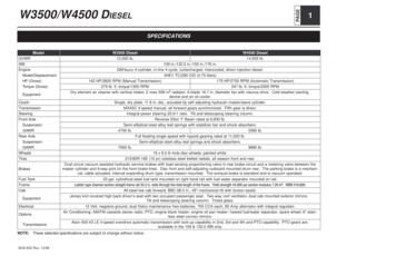
PAGEW3500/W4500 cementHP (Gross)Torque (Gross)EquipmentClutchTransmissionSteeringFront AxleSuspensionGAWRRear AxleSuspensionGAWRWheelsTiresBrakesFuel sW3500 Diesel12,000 lb.109 in./132.5 in./150 in./176 in.GM/Isuzu 4-cylinder, in-line 4-cycle, turbocharged, intercooled, direct injection diesel.4HE1-TC/290 CID (4.75 liters)142 HP/2800 RPM (Manual Transmission)175 HP/2700 RPM (Automatic Transmission)275 lb. ft. torque/1300 RPM347 lb. ft. torque/2000 RPMDry element air cleaner with vertical intake; 2 rows 506 in2 radiator; 6 blade 18.7 in. diameter fan with viscous drive. Cold weather startingdevice and an oil cooler.Single, dry plate, 11.8 in. dia., actuated by self adjusting hydraulic master/slave cylinder.MXA5C 5-speed manual, all forward gears synchronized. Fifth gear is direct.Integral power steering 20.9:1 ratio. Tilt and telescoping steering column.Reverse Elliot “I” Beam rated at 6,830 lb.Semi-elliptical steel alloy leaf springs with stabilizer bar and shock absorbers.4700 lb.5360 lb.Full floating single speed with hypoid gearing rated at 11,020 lb.Semi-elliptical steel alloy leaf springs and shock absorbers.7950 lb.9880 lb.16 x 6.0 6–hole disc wheels, painted white.215/85R-16E (10 pr) tubeless steel belted radials, all season front and rear.Dual circuit vacuum assisted hydraulic service brakes with load sensing proportioning valve in rear brake circuit and a metering valve between themaster cylinder and 6-way joint on the front brake lines. Disc front and self-adjusting outboard mounted drum rear. The parking brake is a mechanical, cable actuated, internal expanding drum type, transmission mounted. The exhaust brake is standard and is vacuum operated.33 gal. cylindrical steel fuel tank mounted on right hand rail with fuel water separator mounted on rail. ! ! ! ! # ! " ! ! ! ! ! ! ! ! " " All steel low cab forward, BBC 68.0 in., 45 mechanical tilt with torsion assist.Jersey knit covered high back driver’s seat with two occupant passenger seat. Two-way roof ventilator, dual cab mounted exterior mirrors.Tilt and telescoping steering column. Tinted glass.12 Volt, negative ground, dual Delco maintenance free batteries, 750 CCA each, 80 Amp alternator with integral regulator.Air Conditioning; AM/FM cassette stereo radio; PTO; engine block heater; engine oil pan heater; heated fuel/water separator; spare wheel; 6” stainless steel convex mirrors.Aisin 450-43 LE 4-speed overdrive automatic transmission with lock-up capability in 2nd, 3rd and 4th and PTO capability. PTO gears areavailable in the 109 & 132.5 WB only.NOTE: These selected specifications are subject to change without notice.W35/45D Rev. 12/98W4500 Diesel14,500 lb.
PAGE2W3500/W4500 DIESELVEHICLE WEIGHTS, DIMENSIONS AND RATINGSW35/45D Rev. 12/98
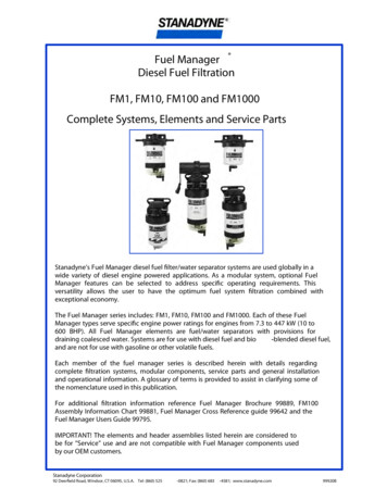
PAGEW3500/W4500 DIESELVariable Chassis DimensionsUnit12,000 lb. GVWR with Aisin Automatic Transmission h176.0155.4198.5266.3Chassis Cab and Maximum Payload WeightsWBUnitFrontRearTotalPayloadNB1109.0 in.lb.3,7041,6315,3356,66543.1NB2132.5 in.lb.3,7481,6535,4016,59943.1NB3150.0 in.lb.3,7921,6755,4676,533NB4176.0 in.lb.3,8361,6985,5346,466* Effective CA & CE are CA or CE less BOC.Model14,500 lb. GVWR with Aisin Automatic Transmission ModelDimension sis Cab and Maximum Payload WeightsModelWBUnitFrontRearTotalPayloadNF1109.0 in.lb.3,7151,6315,3469,15433.5NF2132.5 in.lb.3,7591,6535,4129,088OH87.4NF3150.0 in.lb.3,8031,6755,4789,022OW78.5NF4176.0 in.lb.3,8471,6985,5458,95512,000 lb. GVWR Manual Transmission ModelVehicle weight Limits:Chassis Cab and Maximum Payload WeightsGVWRWBUnitFrontRearTotalPayloadNA1109.0 in.lb.3,6381,5875,2256,775NA2132.5 in.lb.3,6821,6095,291NA3150.0 in.lb.3,7261,631NA4176.0 in.lb.3,7701,653Designed Maximum12,000 lb.14,500 lb.6,709GAWR, Front4,700 lb.5,360 lb.5,3576,643GAWR, Rear7,950 lb.9,880 lb.5,4236,577Technical Notes:14,500 lb. GVWR Manual Transmission ModelChassis Curb Weight reflects standard equipment and fuel, but no driver or payload.Chassis Cab and Maximum Payload WeightsModelWBUnitFrontRearTotalPayloadNE1109.0 in.lb.3,6491,5875,2369,264NE2132.5 in.lb.3,6931,6095,3029,198NE3150.0 in.lb.3,7371,6315,3689,132NE4176.0 in.lb.3,7811,6535,4349,066W35/45D Rev. 12/98Maximum Payload Weight is the allowed maximum for equipment, body, payloadand driver and is calculated by subtracting chassis curb weight from the GVWR.Model DescriptionsThe W3500/W4500 Series Diesel features a low cab forward design that is ideallysuited for inter-city type applications. The low cab forward design minimizes overalllength for a given body length and in conjunction with the set back front axle positioning provides excellent weight distribution. The 42.5 inside wheel cut angle coupledwith integral power steering make it an extremely well maneuverable truck.
PAGE4W3500/W4500 DIESELFRAME & CROSSMEMBER SPECIFICATIONSType AAType BBType CCType DDCross Member Type/LocationModelWheel 1090.2437.028.38.48.4AA 40.5AA 44.7—CC 26.0DD 33.0W3500/W4500132.50.2437.028.38.48.4AA 40.5AA 44.7BB 59.4CC 26.0DD 33.0W3500/W4500150.00.2437.028.38.48.4AA 40.5AA 44.7BB 59.4CC 26.0DD 26.033.0W35/45D Rev. 12/98
PAGEW3500/W4500 DIESELFRAME CHARTVehicle ModelWheel BaseFrame FLFrame 253.40.24W35/45D Rev. 12/985
PAGE6W3500/W4500 DIESELAUXILIARY VIEWSNOTE: Frame mounted fuel tank available on 109:, 132.5”, 150: and 176” WB: In frame mounted tank available as optional replacement for frame mountedtank on 109”, 132.5”, 150” and 176” WB.* Allow 3” additional for battery box opening clearance.W35/45D Rev. 12/98
PAGEW3500/W4500 DIESEL7BODY BUILDER WEIGHT INFORMATION CHARTWheel BaseGVWR12,00014,500Cab Tilt109 in.Axle132.5 in.150 in.176 in.UnsprungUWeightMan. Trans.Auto. Trans.Man. Trans.Auto. Trans.Man. Trans.Auto. Trans.Man. Trans.Auto. er of GravityGVWR12 00012,00014 50014,500WBV109HManual Trans.Auto. 20.545.645.917618.953.553.6V Vertical Center of GravityH Horizontal Center of GravityThe center of gravity of the completed vehicle with a full load shouldnot exceed 54 inches above groundlevel for the 12,000 lb. GVWR, 58inches above ground level for the14,500 GVWR, and must be locatedhorizontally between the centerlines of the front and rear axles.NOTE: The maximum dimensions for a body installed on the W3500/W4500 are 96 inches wide (outside) by 90 inches high (inside). Any larger body applications must be approvedby GM/Isuzu Application Engineering. In the West Coast call 1-562-699-0500, extension 2385 and in the East Coast call 1-770-475-9195 extension 353.W35/45D Rev. 12/98
PAGE8W3500/W4500 DIESELFRONT AXLE CHARTFormulas for calculating height dimensions:ACDCHDH Tire Loaded Radius-BCenterline of Axle to Top of Frame Rail at Curb PositionCenterline of Axle to Top of Frame Rail at Design LoadC Tire Unloaded RadiusD Tire Loaded RadiusTire215/85R 1616-EEGVWRGAWRABCDCHDHTrack11,050 lb.4,700 lb.7.76.413.012.527.326.614,500 lb.5,360 lb.7.76.413.012.527.326.6Tire RadiusUnloadLoad65.614.314.165.614.314.1W35/45D Rev. 12/98
PAGEW3500/W4500 DIESELREAR AXLE CHARTW35/45D Rev. 12/989
PAGE10W3500/W4500 DIESELDefinitionsRear Frame Height:Vertical distance between the normal top of frame rail and the ground-line throughthe center line of the rear axle at design load.ACenter line of axle to bottom of axle bowl.DHBCenter line of axle to top of frame rail at metal to metal position.DW Minimum distance between the inner surfaces of the rear tires.CCenter line of axle to top of frame rail at curb position.EWMaximum Rear Width:Overall width of the vehicle measured at the outer most surface of the rear tires.DCenter line of axle to top of frame rail at design load.HHRear Tire Clearance:Minimum clearance between the rear axle and the ground-line.ERear Tire Clearance:Minimum clearance required for tires and chain measured from the top of theframe at the vertical center line of the rear axle, when rear wheels on one sideride over a high spot.Dual Tire Spacing:Distance between the center lines of the minimum distance required for tireHWbounce as measured from the center line of the rear axle and the top of the reartire when one wheel rides over a high spot.Rear Frame Height:Vertical distance between the normal top of frame rail and the ground-line throughthe center line of the rear axle at curb position.Track Dual Rear Wheel Vehicles:CW Distance between the center lines of the distance between the center lines of thedual wheels measured at the ground-line.CHTire SectionTire RadiusSee Tire Chart for ValuesTire Loaded RadiusTire ClearanceFormulas for Calculating Rear Width and Height DimensionsCW TrackHH Tire loaded radius – ACH Tire loaded radius CJH KH – BDH Tire loaded radius DKH Tire radius 3.00 inchesDW Track 2 tire sections – tire clearanceKW DW – 5.00 inchesEWLW 1.00 inch minimum clearance between tires and springs Track 2 tire sections tire clearanceNOTE: Track and overall width may vary with optional equipment.TireGAWRTrack CWABCDE215/85R16-E7950/9880 lb.65.010.610.614.913.37.8W35/45D Rev. 12/98
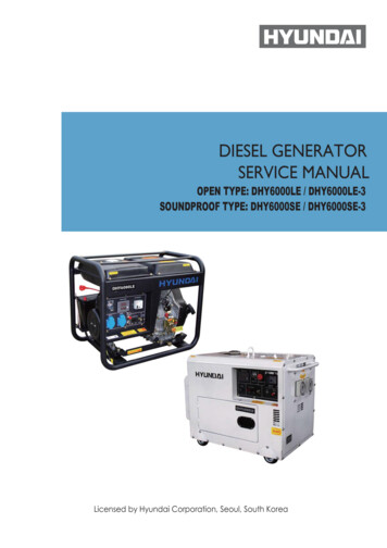
PAGEW3500/W4500 DIESELSUSPENSION DEFLECTION CHARTSFront Leaf Spring Load vs. Deflection(Per Axle)SUSPE 10,000 lbsNSION5,000 lbsLOADSUSPENSIONK 1,843 lb/in14,500 GVW12,000 GVWLOAD01234VERTICAL SPRING DEFLECTION(INCHES)W35/45D Rev. 12/98Rear Leaf Spring Load vs. Deflection(Per Axle)510,000 lbsK 6,935 lb/in14,500 GVW12,000 GVW5,000 lbsK 1,926 lb/in14,500 GVWR12,000 GVWR01234VERTICAL SPRING DEFLECTION(INCHES)11
PAGE12W3500/W4500 DIESELTIRE AND DISC WHEEL CHARTTireTire Load Limit and Cold Inflation PressuresSingleTire SizeMaximum Tire Load LimitsDualFrontRearGVWR (Lb.)Lb.PSILb.PSI2 Single4 Dual215/85R 16-E2430702210704860884012,000215/85R 16-E2680802470805360988014,000Tire RadiusTire SizeLoadedGVWR (Lb)UnloadedFrontRearFrontRearTire STiSectiontiWidthTire ClearanceDesignDiRiRimWidth215/85R 16-E12,00014.114.114.314.78.21.86.0215/85R 16-E14,50014.114.114.314.78.21.86.0Disc WheelWheel SizeBolt HolesBolt CircleDia.Ft./Rr NutSize*Rear StudSize*Nut/StudTorqueSpecs.Inner CircleOutsideOffsetDiscThicknessRim TypeMaterial Mfg.16 x 6.00K6 JIS8.751.6142(41 mm)BUD HEX0.8268(21 mm)SQUARE289 ft-lb(392 N m)6.465.00.355 DCSteelTOPY* O.D. Wrench SizesW35/45D Rev. 12/98
PAGEW3500/W4500 DIESEL13PROPELLER SHAFTPlan ViewSide ViewWheel BaseAManual Trans.AAuto. Trans.BManual Trans.BAuto. Trans.CManual Trans.CAuto. Trans.DManual Trans.DAuto. Trans.109 in.——2.0 2.3 ——8.3 —132.5 in.0 0 2.4 2.4 4.4 5 6.2 6.1 150 in.0 0 2.4 2.4 2.5 2.6 6.4 6.4 176 in.0 0 1.7 1.7 2.8 2.8 4.5 4.5 NOTE: All driveline angles are at unloaded condition (Curb position with typical cargo body).W35/45D Rev. 12/98
PAGE14W3500/W4500 DIESELUnit: InchWheel Base109132.5150176No. of Shafts1222Trans. Type5 Manual Trans.4 Auto. Trans.5 Manual Trans.4 Auto. Trans.5 Manual Trans.Shaft #1 O.D.3.25Thickness0.0914 Auto. Trans.5 Manual Trans.4 Auto. AAAAAAShaft #2 52.652.6TypeN/AN/ABBBBBBTypeDescriptionType A1st shaft in 2 piece drivelineIllustrationLengthType B1st shaft in 1 piece driveline2nd shaft in 2 piece drivelineLengthW35/45D Rev. 12/98
PTO LOCATION, DRIVE GEAR AND OPENING INFORMATIONManual TransmissionAutomatic TransmissionW35/45D Rev. 12/98PAGEW3500/W4500 DIESEL15
PAGE16W3500/W4500 DIESELTrans.OpeningLocationBoltPatternABCDEFHPTO Drive GearRation of PTO DrvNo. ofLocationGear Spd to Eng Spd TeethPitchHelixAngleMax. Output TorqueMXA 5CLeft(Dr 1)13.2393.411.27.12.5 4.12nd Gear Trans.Countershaft25/49 .51203.17515 145 lb-ft @ 1000 RPMAisin1)Left(Dr 2)12.6 087.52.5 4.48PTO Gear1:1 with turbine58N/A0134 lb-ft @ 1500 RPM1) No PTO gear in the 150” WB modelsOpening DiagramW35/45D Rev. 12/98
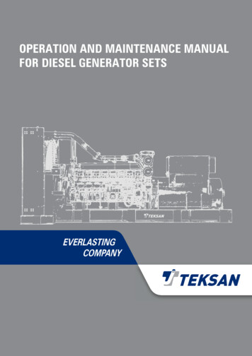
PAGEW3500/W4500 DIESELBRAKE SYSTEM SCHEMATICVacuum Over Hydraulic2LSPV4EXH. BRAKE UNIT1V/PUMP36–WAYM/VACFGACD2EBV/TANKV/PUMPBrake HoseVacuum HoseBrake HoseVacuum Hose1. Brake Hose M/V 6–WayA. V/Hose; M/VAC–Pipe2. Brake Hose FTB. V/Hose; V/Tank–Pipe3. Brake Hose RRC. V/Hose; Floor–Frame4. Metering ValveD. 3–Way Joint Asm.; V/PumpE. V/Hose; M/Valve–PipeF. V/Hose; M/Valve–E/UnitG. V/Hose; M/VAC–V/PumpW35/45D Rev. 12/98MAG/VALVE17
PAGE18W3500/W4500 DIESEL1999 MODEL DIESEL FUEL FILLERInstallation Instructions1. Disconnect Battery2. Take out hoses, clips, pipe joint support bracket (3), filler neck, fuel filler cap andprotective wrap from storage box. Mount support bracket on rail per drawing #1.Bracket location is at 20.55 inches.3. Remove the temporary filler cap from the tank.4. Install 90 hose (1) on the fuel tank neck. Secure with clip (9) hose lengths areset for 96 inch wide body to adjust for narrower body .See drawing #2.5. Place pipe joint (11) in open end of hose and clamp with clip (9). See drawing #3.6. Place other piece of filler hose and vent hose tube through the protective wrapand join with 90 hose at the pipe joint use clips to secure hose.7. Make sure the vent tube hose is placed on top of the filler hose inside the protective wrap. This
Model W3500 Diesel W4500 Diesel GVWR 12,000 lb. 14,500 lb. WB 109 in./132.5 in./150 in./176 in. Engine GM/Isuzu 4-cylinder, in-line 4-cycle, turbocharged, intercooled, direct injection diesel. Model/Displacement 4HE1-TC/290 CID (4.75 liters) HP (Gross) 142 HP/2800 RPM (Manual Transmission) 175 HP/2700 RPM (Automatic Transmission)