Transcription
UL approvedfor ANSI/SIACP-01-2000NetworX Series NX-4 Control PanelInstallation and Startup
2012 UTC Fire & Security Americas Corporation, Inc.Interlogix is part of UTC Climate Controls & Security,a unit of United Technologies Corporation.All rights reserved.Printed in the USA.These instructions do not purport to cover all details or variations in equipm ent nor to provideevery possible contingency to be met during installation, operation, and maintenance. If furtherinformation is desired or if particular problem s arise that are not covered sufficiently for thepurchaser’s purpose, the matter should be referred to UTC Fire & Security, Gladewater, Texas, USA.This document contains proprietary inform ation of UTC Fire & Security, USA and is furnished to itscustomer solely to assist that customer in the installation, testing, operations, and/or maintenanceof the equipment described. This document shall not be reproduced in whole or in partnor shallits contents be disclosed to any third party without the written approval of UTC Fire & Security.Please refer to the current UTC Fire & Security product catalog for detailed warranty information.Main800-727-2339903-845-6941Outside the USMain nical SupportTech Support FaxSales & LiteratureNetworX is a trademark of the UTC Fire & Security companies.800-727-2339903-845-8409800-547-2556
NetworX NX-4Control/CommunicatorInstallation ManualPageGeneral Description . 2Ordering Information. 2Board Installation . 2Feature Definitions . 3Programming the LED Keypads . 8Programming the NX-4 .10Types of Programming Data .10Enrolling the Modules & Keypads.12Communicator Formats.13Reporting Events to Phone #1, #2, & #3 . 13-15Zone Doubling .18Programming the Outputs . 19-20Standard Zone Types (Configurations) .25Programming Worksheets . 26-32SIA and Contact ID Formats . 33-34Expander Trouble Reporting Information .35Wiring Diagram .36Terminal Description .37Telephone Interface Information .39Underwriters Laboratories Information .39SIA / ANSI CP-01 Requirements.41Specifications . Back PageUTC Fire & Security1-800-727-2339
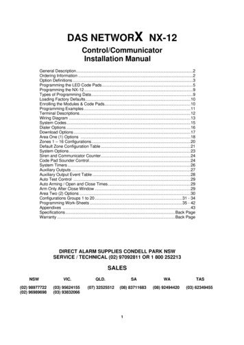
NX-4 ControlGENERAL DESCRIPTIONThe NetworX NX-4 represents a new approach to security systems design. Drawing on our experience in the worldmarket as the largest exporter of USA manufactured controls we have developed the most flexible, durable, and userfriendly control ever seen in our industry. Featuring sophisticated software which allows up to 8 users to interface with8 zones, and a host of integrated fire, access, verification, and input/output modules, all reported with the mostcomprehensive and fast SIA and Contact ID formats. The NetworX design allows a fully loaded system to be housed inone single metal enclosure, establishing for the first time, a logical solution and design response to modular systems.A maximum of 8 keypads and 1 other module (excluding hardwire) can be added to expand the capabilities of the NX4 unit. For warranty information, please refer to the current Security Product Catalog.ORDERING INFORMATIONPART #DESCRIPTIONPART #DESCRIPTIONNX-4-KITNX-4 Control, NX-108E LED Keypad, &16.5V 40VA TransformerNX-108E8 Zone LED KeypadNX-4NX-4 Control OnlyNX-116E16 Zone LED KeypadNX-200 **Zone Doubling Kit (Includes 100 3.74kand 100 6.98k resistors)NX-124E24 Zone LED KeypadNX-320ESmart Power Supply and Buss ExtenderNX-148EAlphanumeric LCD KeypadNX-408E #8 Zone Wireless Expansion Module(UL LISTED PART #60-904)NX-1192E192 Zone LCD KeypadNX-416E #16 Zone Wireless Expansion Module(UL LISTED PART #60-904)NX-1208E8 Zone LED KeypadNX-448E #48 Zone Wireless Expansion Module(UL LISTED PART #60-904)NX-1248E48 Zone LCD KeypadNX-508EEight Output ModuleNX-1308E8 Zone LED Door Design KeypadNX-534E **Two-Way Listen In ModuleNX-1316E16 Zone LED Door Design KeypadNX-540E **"Operator II" Telephone Interface ModuleNX-1324E24 Zone LED Door Design KeypadNX-591E **Cellemetry InterfaceNX-1448E48 Zone Fixed Language IconKeypad** These products have not been tested and approved by Underwriters Laboratories, Inc.# These wireless devices are only UL listed for residential applications.IMPORTANT NOTES1.2.The maximum number of zones available is 8 regardless of devices added. Information regarding Zone Doublingis located on page 7.The NX-4 control panel will send an “Expander Trouble” once each hour if it senses that no devices have beenenrolled. This report will show “Expander Trouble” - device zero (0).BOARD INSTALLATIONThe metal enclosure should be installed with the door opening from topto bottom. Refer to the diagram on the right.Inside the can, there are four slots for board insertion, two on the topand two on the bottom of the can. These allow the PC board to bepositioned vertically as shown in the diagram. When you slide theboard between the grooves of the slots, make sure the terminal strip istoward the front for wire connections.Page 2
NX-4 ControlFEATURE DEFINITIONSAbortIf enabled, the NX-4 will wait the programmed number of seconds in location 40 prior to sending an alarm. Duringthis delay time, the "Cancel" LED will flash. To abort the report, type in a code and press the [Cancel] key. TheLED will extinguish. If the report is not aborted within the allotted time, the LED will extinguish when the report issent. (Loc. 40 and 110-149, pages 18 and 24)AC Fail / Low Battery Report/WarningThe NX-4 can be programmed to report AC failure and/or Low Battery conditions to the central station. It can alsobe programmed to sound the keypad immediately upon detection of the condition. The AC failure report/warningcan be delayed. (Loc. 37 and 39, page 17 - 18)AC Power / Low Battery Sounder AlertIf enabled, the NX-4 will beep the keypad sounder upon arming or disarming if the AC power is missing or a lowbattery has been detected. (Loc. 23, page 16)Arm / Disarm CodesThe NX-4 can have 8 four-digit codes OR 8 six-digit codes to arm/disarm the control. All codes must have thesame number of digits. The factory default for User #1 is [1]-[2]-[3]-[4] when using a 4-digit code, or [1]-[2][3]-[4]-[5]-[6] for a 6-digit code. This code can then be used to enter the new arm/disarm codes. (Loc. 41,page 19)Automatic ArmingIf programmed, the NX-4 will Auto Arm at the time specified in location 53. At that time, the keypad will beep for50 seconds before the panel arms. The arming process will be stopped if a code is entered on the keypad. The NX4 will attempt to arm after every 45 minutes of inactivity until the next Aopening@ time (loc. 52), or until the systemis armed. The 45-minute timer will be extended when there is activity in the building causing the "Ready" LED toturn off and on. If closing reports are sent, the user code will be 97. (Loc. 23, and 52-55, pages 16 and 21.NOTE: For UL installations, this feature shall be disabled.)Automatic Bypass / Instant ArmingWhen enabled, the control panel can automatically bypass interior follower zones if an exit is not detected duringthe exit delay time. Entry delay zones can also be made instant. (Loc. 23, segments 1 & 3, page 16)Auto Cancel / AbortIf enabled, Cancel and/or Abort features will be automatic (means pressing the Cancel button is not required.) TheCancel / Abort features, in Locations 23 and 40 respectively, must be enabled to permit this Auto feature to work.For proper operation of these features, ADialer Delay@ must be enabled in ACharacteristic Select@ of Locations 110149 Zone Configuration Groups. (Loc. 41, page 19)Auto TestThis feature will cause the panel to call the central station to report a communicator test at a specified interval.(Loc. 37 - Seg. 4, and Loc. 51, pages 17 and 20)Auxiliary OutputsThe NX-4 has two programmable outputs that can be used to activate relays, LED s, etc. (See the terminaldescription on page 37 and locations 45-50, pages 19-20)Auxiliary Power Over-currentThe NX-4 will illuminate the "Service" LED on the keypad whenever too much current is drawn from any devicepowered by the system. This condition can be reported to the central station. Power down the system to clear.(Loc. 37, page 17)Box TamperThe NX-4 has an input for a normally closed tamper switch (see terminal drawing). The Box Tamper can beprogrammed to report and/or sound the siren and/or the keypad. These terminals can be enabled or disabled inprogramming. (Loc. 37 and 39, page 17)Page 3
NX-4 ControlBuilt In Siren DriverThe NX-4 has a built-in 112db siren driver. When desired, this built-in driver can be easily converted to a 1 ampvoltage output through programming. (Loc. 37, page 17)Bypass ToggleThis feature will enable the end user to toggle (turn on or off) the bypass of an interior zone with the system armedby pressing the [Bypass] key. (Loc. 23, page 16)Call BackWhen enabled, the control will use the call back phone number to call the download computer before beginning adownload. (Loc. 21, page 16)CancelIf enabled, the NX-4 will send a "Cancel" report if when the system is disarmed and the [Cancel] button is pressedwithin 5 minutes of an alarm. Once the [Cancel] key is pressed, the "Cancel" LED will illuminate until the centralstation acknowledges the "Cancel" report. ADialer Delay@ must be enabled in the ACharacteristic Select@ of Loc. 110149. (Loc. 23, page 16)Code Required OptionsThe NX-4 can be programmed to require a code for bypassing zones and/or initiating a download using the [r]-[9][8] or [r]-[9]-[9] function. (Loc. 23 and 41, pages 16 and 19)Communication FormatsThe NX-4 can report in multiple formats. It is recommended that you use Contact ID or SIA formats if possible. Ifyou wish to report to a pager or in a 4 2 format to a central station, you must program each code to be reported.(Loc. 56-83 and 111-149, pages 22-25)Configuration GroupsThe NX-4 has 20 programmable configuration groups that determine how each zone will function and report. Thedefault configuration groups (Zone Types) are listed on page 25. (Loc. 111-149, pages 24-25)Cross ZoningThis feature requires two or more trips on a zone or zones programmed as "cross zones" within a specified timebefore reporting an alarm. During the time between trips, the NX-4 can be programmed to sound the keypadand/or the siren. The NX-4 can also be programmed to report an alarm after two or more trips on the same zone.(Loc. 37, 39, 40 and 110-149, pages 17 - 18, 24 - 25)Dual / Split / Multiple ReportsThe NX-4 can send communication reports to three different phone numbers for dual, split or multiple reportsselectable by event. (Loc. 4, 10, and 16, pages 13-15)Duress CodeIf a duress code is programmed, the NX-4 will send a duress signal whenever the panel is armed or disarmed withthis code. If open/close reports are sent, the user code will be 254. (Loc. 44, page 19)Dynamic Battery TestThe NX-4 can be programmed to perform a Dynamic Battery Test for a selected duration the first time the panel isarmed or disarmed every day, as well as by pressing [t][4] Test Function. The NX-4 can also be programmed toperform a missing battery test every 12 seconds. (Loc. 37 and 40, pages 17 and 18)Entry-GuardThis unique low level arming mode has been developed to reduce the most common source of false alarms. Whenarmed with the Instant light on, the opening of any zones designated as "Entry Guard zone" will initiate the keypadsounder and start the entry delay before creating an alarm. All other zones will function as normal. This armingmode will encourage system owners to use their system more frequently when the premise is occupied. (Loc. 111149, pages 24-25 NOTE: For UL installations, this feature shall be disabled.)Page 4
NX-4 ControlExit ErrorIf enabled, the NX-4 will send an "Exit Error Report" if an entry/exit zone is faulted at the instant the exit delayexpires. This report will be sent along with the user number that armed the system, if the panel is not disarmedbefore the entry delay expires. The alarm report will also be sent. Even if this feature is not enabled, the siren willsound if any entry/exit zone is faulted at the instant the exit delay expires. (Loc. 23, page 16)Expander TroubleThe NX-4 will report expander trouble to the central station if enabled. This condition will illuminate the "Service"LED on the keypad even if not reported. NOTE: The keypads are considered expanders. The number of theexpansion devices reported can be found on page 35. (Loc. 37, page 17)Fail to CommunicateThe NX-4 will illuminate the "Service" LED if a report fails to reach the central station. If enabled, when the nextreport is successfully communicated, a Fail to Communicate code will be reported. (Loc. 37, page 17)Fire Alarm VerificationWhen enabled, the NX-4 will verify a Fire alarm by requiring more than one trip on a smoke detector within aspecified time before creating an alarm. NOTE: For household systems, the Fire Alarm Verification feature is NOTapproved for use in California. This feature shall not be programmed into the control unit. (Loc. 40, page 18)Force ArmingWhen enabled, the NX-4 can be Force Armed with zones violated. Under this condition, if a force armable zone isnot secure, the "Ready" LED will flash. At the end of the exit delay, these zones will become bypassed. If thesezones become secured any time during the arming cycle, they will be unbypassed and active in the system. If"Bypass Report" is enabled, the force arming zones can be programmed to report bypass when they are ForceArmed (default), or to not report bypass even if "Bypass Report" is enabled. (Loc. 37, and 111-149, pages 17& 24-25 NOTE: For UL installations, this feature shall be disabled.)Group BypassA designated group of zones can be programmed to bypass by pressing [Bypass]- [0]-[Bypass]- [Bypass] priorto arming. (Loc. 111-149, pages 24-25 NOTE: For UL installations, this feature shall be disabled.)Immediate Restore By ZoneThe NX-4 can be programmed to send alarm and restore reports as soon as they occur, or wait until the siren timehas expired. (Loc. 37, page 17)Internal Event LogUp to 185 events can be stored in memory along with the date and time of the event. These events can later beviewed through downloading or on the LCD keypad. All reportable events report to the log.Keypad Activated PanicsThe NX-4 has three keypad activated panics that will send reports to the central station: Auxiliary 1 (Fire), Auxiliary2 (Medical), and Keypad Panic. Auxiliary 1 will activate the steady (Fire) siren, Auxiliary 2 will sound the keypad,and the Keypad Panic can be programmed to be silent or audible (sound siren). (Loc. 23, page 16)Keypad Sounder ControlThe NX-4 can be programmed to sound the keypad sounder for certain events. (Loc. 39, page 18)Keypad TamperIf enabled, the NX-4 will disable the keypad for 60 seconds and communicate a tamper signal to the central stationif 30 keypresses are entered without producing a valid code. (Loc. 23, page 16)LED ExtinguishThis feature will extinguish all LED s on the keypad, except the "Power" LED, after 60 seconds without a keypress.Pressing any numeric key will illuminate all LED s. (Loc. 23, page 16)Page 5
NX-4 ControlLocal Programming LockoutThis feature will disable programming of all locations or specified locations from the keypad. (Loc. 21, page 16)Log Full ReportA report can be sent to the central station when the event log is full. (Loc. 37, page 17)Lost Clock Service LightThe NX-4 can be programmed to illuminate the "Service" LED when the internal clock has an invalid time due topower loss. (Loc. 37, page 17)Manual TestThe NX-4 can be programmed to perform a bell and/or communicator test when [r]-[4] is entered while thesystem is in the disarmed state. (Loc. 37, page 17)On Board Zone DisableThe four zones on the NX-4 panel can be disabled in order to have a completely wireless alarm system. (Loc. 37,page 17)Program CodeThe factory default for the "Go To Program" code is [9]-[7]-[1]-[3] when using a 4-digit code or, if the 6-digitoption is used, the default is [9]-[7]-[1]-[3]-[0]-[0]. The program code can also be used as an Arm/Disarm code.If used as an Arm/Disarm code, and open/close reports are sent, the user code will be 255. (Loc. 43, page 19)Quick Arm FeatureThe NX-4 has a one button "Quick Arm" feature which can be used to arm the system by pressing the [Exit] key orthe [Stay] key. If closing reports are sent, the user code will be 98. (Loc. 23, page 16)Recent ClosingIf enabled, the NX-4 will send a "Recent Closing Report" to the central station if an alarm occurs within 2 minutesafter the panel is armed. The user number that armed the system will also be sent. (Loc. 23, page 16)Re-exitThe NX-4 has the ability to restart the exit delay for a quick exit without disarming the system by pressing the[Exit] key while the system is armed. (Loc. 23, page 16)ShutdownThis mode will cause the keypads to turn off all LED s, except the "Power" LED, and not accept keypresses. (Loc.21, page 16)Siren Blast For ArmingThe NX-4 can be programmed to give a one-second siren blast when the panel is armed, at the end of the exitdelay, or when the central station receiver acknowledges the closing report. It can also give one blast for wirelessarming and two blasts for wireless disarming. (Loc. 37, page 17)Siren SupervisionThe NX-4 has a ASiren Supervision@ circuit that will constantly monitor the siren on the NX-4 and can beprogrammed to report if the wires are cut. (Loc. 37, page 17)Silent Exit OptionThe exit delay can be silenced by pressing [r]-[Exit] before arming the control panel, or when using the re-exitfeature.Start/End Programming and End DownloadingA report can be sent when local programming is started and ended. A report can also be sent when a downloadsession ends. (Loc. 37, page 17)Page 6
NX-4 ControlSwinger ShutdownThis feature allows a zone(s) to be automatically bypassed after a specified number of alarms. When a zone istripped, the alarm ‘counter’ reflects “1” in memory. If a new (first) alarm is detected in a different zone, thecounter remains at “1”. If an alarm is detected on a previously tripped zone, the count increments to “2”. The‘counter’ will increment each time an alarm is detected on a zone with multiple trips. Bypassing will occur on thezone that causes the count to equal the number programmed in location 38; the ‘counter’ will reset to zero (0); andbegin a new trip count where the next alarm will set the ‘counter’ to 1. If immediate restore is enabled in location37, the alarms (and restores, if enabled) will be sent as they occur. If immediate restore is not enabled, a secondor subsequent alarm will not be sent until the siren times out. Factory default is 1. (Loc. 37 and 38, page 17)Temporal Siren DisableIf disabled, the Fire Siren will be steady and Fire Voltage Out will be the same as Burglary (continuous). Otherwise,the Fire Siren will be temporal. (Loc. 37, page 18 NOTE: For UL installations, do NOT disable.)Two Call Answering Machine DefeatIf enabled, to defeat an answering machine, two telephone calls must be made to the premises. On the first call, letthe phone ring one or two times. The control panel will detect these rings and start a 45-second timer, duringwhich, the control panel will answer the next call on the first ring. This is not recommended for commercialapplications. (Loc. 21, page 16)Walk-Test Mode[r] [Chime]If enabled, entering [r] [Chime] followed by a user code will allow a walk-through zone test where all zonesbecome silent and local (non-reporting). Each time a zone is faulted, the zone light on the LED keypad willilluminate and the chime will sound. The number of the faulted zone(s) will be displayed on the LCD keypad. It willalso be entered into alarm memory and the internal log. To exit at any time during this mode, enter a user code.Otherwise, the AWalk-Test Mode@ will automatically exit after 15 minutes. (Loc. 41, page 19)Wireless Sensor Missing/Low BatteryThe NX-4 will send a report to the central station when a wireless sensor has detected a low battery or has notreported to the receiver. The "Service" LED will illuminate when either condition exists. (Loc. 37, page 17)Zone Bypassed Sounder AlertIf this feature is enabled, the NX-4 will beep the keypad sounder upon arming if a zone is bypassed. (Loc. 23,page 16)Zone Doubling (Requires additional devices)Zone doubling can only be enabled when at least one other device is added to the basic system (consisting ofthe main control panel and one keypad). Additional devices can include wireless receivers, extra keypads,etc. If enabled, this feature allows you to use the four zones on the panel as eight normally closed zones.When this feature is used, European double E.O.L. configuration cannot be used. THIS FEATURE DOESNOT INCREASE THE TOTAL NUMBER OF AVAILABLE ZONES BEYOND 8. If one of the eight zones mustbe a fire zone, it must be one of Zones 1 - 4. The corresponding upper zone will become unavailable. Forexample, if Zone 4 is a fire zone, then Zone 8 will not be available. (Loc. 37, page 17)Page 7
NX-4 ControlPROGRAMMING THE LED KEYPADSThis section describes how to program the address of each keypad as well as the options that are available. Theaddress of the keypad is important because this is how the panel supervises the keypads. The factory default for theMaster code is [1]-[2]-[3]-[4] when using a 4-digit code or [1]-[2]-[3]-[4]-[5]-[6] for a 6-digit code. The factorydefault for the "Go To Program" code is [9]-[7]-[1]-[3] for a 4-digit code or [9]-[7]-[1]-[3]-[0]-[0] for a 6-digitcode.[r]-[9]-[3] Set keypad options1. Enter [r]-[9]-[3] [program code]. The "Service" LED will flash.2. LEDs 1-8 can now be toggled on/off to enable/disable the following functions:3. After enabling/disabling the desired functions, press [r]LEDKEYPAD FEATURE ENABLED1RESERVED.DO NOT PROGRAM THIS AT ALL!2Enable Silent Keypad option - silences the entry/exit sounder & chime only.3Enable Ding Dong sound for Chime - If off, chime will be a single tone. (See location 40, page 18)4Enable Keypress Silence option - silences the pulsing keypad sounder for 5 seconds when a key ispressed5Enable Armed Status Suppression - will not allow the keypad to display faulted or bypassed zones whenthe system is armed6Enable Panic, Fire, Medical Beeptone - will sound a short beep to verify that the keypress was accepted7Suppresses the "Service" LED - will not allow the "Service" LED to illuminate for any reason. If there is asystem trouble, pressing [r]-[2] will still show the service menu. (NOTE: For UL installations, the ServiceLED shall not be suppressed)8RESERVED. This LED should always be “OFF”.[r]-[9]-[4] Set keypad number1. Enter [r]-[9]-[4]-[program code]. The "Service" LED and the "Instant" LED will flash.2. Enter the keypad number (1-8).3. Press [r]. The "Instant" LED will illuminate steady and the"Service" LED will remain flashing.4. Enter [1]. The keypad will automatically exit this mode at this time.[r]-[9]-[5] Set elapsed increments since last autotest1. Enter [r]-[9]-[5]-[program code]. The "Service" LED will flash.2. Enter [100's digit]3. Enter [10's digit]4. Enter [1's digit]5. Press [#] to save and exit.[r]-[9]-[6] Set system date1. Enter [r]-[9]-[6]-[master code]. The "Service" LED will flash.2. Enter [day of week (1 Sun)]3. Enter [month 10's digit]4. Enter [month 1's digit]5. Enter [day 10's digit]6. Enter [day 1's digit]7. Enter [year 10's digit]8. Enter [year 1's digit][r]-[9]-[7] Set system clock1. Enter [r]-[9]-[7]-[master code]. The "Service" LED will flash.2. Enter [hour 10's digit]3. Enter [hour 1's digit]4. Enter [minutes 10's digit]5. Enter [minutes 1's digit]Page 8
NX-4 ControlCHANGING USER CODES:1. Enter [r]-[5]-[master code]. The "Ready" LED will flash.2. Enter the 2 digit user number (always 2 digits such as "03" for user 3). The "Ready" LED will illuminatesteady.3. Enter the new user code designated for that individual. The "Ready" LED will flash indicating that the codewas accepted. If it rejects the code, the sounder will beep 3 times. Note for NX1300 Series LED Keypad:The zone lights will illuminate specifying the first digit of the “user code”. (Lights 1-8 on code is blank; lights1-8 off “0"; lights 1 and 8 “9".) Use the up and down scroll keys to view the next digit or enter a new 4or 6-digit “user code”. While using the scroll keys you can change any digit by entering a new digit. This willadvance you to the next digit.4. If another user code needs to be programmed, return to step 2.5. Press [#] while the "Ready" LED is flashing to exit the User Code Programming Mode.ASSIGNING AUTHORITY LEVEL:1. Enter [r]-[6]-[master code]. The "Ready" LED will flash.2. Enter [2 digit user number] (always 2 digit such as 03 for user 3). The "Ready" LED will illuminate steady andthe "Instant" LED will flash3. Refer to this chart for the description of each LED. Turn the LED on for the features that you desire.LEDATTRIBUTES IF LED 8 IS OFFLEDATTRIBUTES IF LED 8 IS ON1Reserved1Activate output #12Arm Only2Activate output # 23Arm Only After Close Window3Reserved4Master arm/disarm (can program other codes)4Reserved5Arm/disarm code5Arm/disarm6Allowed to bypass zones (see location 23)6Bypass Zones7Code will send open / close reports7Open / Close Reporting8If this LED is on, LEDs 1-7 will use the chart to theright8If this LED is off, LEDs 1-7 use the chart to theleft4.Enter [r] [r]. This step returns you back to step 2 above. At this point you may enter another user numberto assign attributes for. You may continue this procedure until you have assigned authority levels to all usernumbers - or - you may press [#] key to exit the Assigning Authority Level Program.[r]-[9]-[8]Pressing [r]-[9]-[8] while the system is disarmed will cause the control to do a callback for a download.NOTE: A VALID USER CODE MAY BE REQUIRED AFTER [r]-[9]-[8] IF ENABLED IN LOCATION 41,PAGE 19.[r]-[9]-[9]Pressing [r]-[9]-[9] while the system is disarmed will cause the control panel to seize the phone line for adownload. NOTE: A VALID USER CODE MAY BE REQUIRED AFTER [r]-[9]-[9] IF ENABLED INLOCATION 41, PAGE 19.Page 9
NX-4 ControlPROGRAMMING THE NX-4 CONTROLENTERING THE PROGRAM MODE: To enter the Program Mode, press [r]-[8]. At this time, the five function LEDs(Stay, Chime, Exit, Bypass, & Cancel) will begin to flash. Next, enter the "Go To Program Code" (FACTORY DEFAULTIS [9]-[7]-[1]-[3]). If the "Go To Program Code" is valid, the "Service" LED will flash and the five function LEDs willilluminate steady. You are now in the Program Mode and ready to select the module to program.SELECTING THE MODULE TO PROGRAM: Since all modules connected to the NX-4 are programmed through thekeypad, the module you are programming should be the first entry. To program the NX-4 Control Panel, enter [0][#]. The [0] is the module number of the control and the [#] is the entry key. Other module entry numbers can befound in their corresponding manuals.PROGRAMMING A LOCATION: Once the number of the module to be programmed has been entered, the "Armed"LED will illuminate, indicating it is waiting for a programming location to be entered. Any location can be accessed bydirectly entering the desired programming location followed by the pound [#] key. If the location entered is a validlocation, the "Armed" LED will extinguish, the "Ready" LED will illuminate and the binary data for the first segment ofthis location will be shown by the zone LED's. While entering new data, the "Ready" LED will begin flashing to indicatea data change in process. The flashing will continue until the new data is stored by pressing the [r] key. Uponpressing the [r] key, the keypad will advance to the next segment and display its data. This procedure is repeateduntil the last segment is reached. Pressing the [#] key will exit from this location, and the "Armed" LED will illuminateagain waiting for a new programming location to be entered. If the desired location is the next sequential location,press the [POLICE] key. If the previous location is desired press the [FIRE] key. If the same location is desired pressthe [MEDIC] key. To review the data in a location, repeat the above procedure, pressing the [r] key without anynumeric data entry. Each time the [r] key is pressed, the programming data of the next segment will be displayed forreview.EXITING A LOCATION: After the last segment of a location is programmed, pressing [r] will save the data, exit thatlocation, turn the "Ready" LED off and the "Armed" LED on. To exit before the last segment, press [#]. As before, youare now
NX-4 Control Page 2 IMPORTANT NOTES GENERAL DESCRIPTION The NetworX NX-4 represents a new approach to security systems design. Drawing on our experience in the world