Transcription
Signal Generator Fundamentals
Signal Generator FundamentalsTable of ContentsThe Complete Measurement System · · · · · · · · · · · · · · · 5Complex Waves · · · · · · · · · · · · · · · · · · · · · · · · · · · · · · · · · 15The Signal Generator · · · · · · · · · · · · · · · · · · · · · · · · · · · · 6Signal Modulation · · · · · · · · · · · · · · · · · · · · · · · · · · · 15Analog or Digital? · · · · · · · · · · · · · · · · · · · · · · · · · · · · · · 7Analog Modulation · · · · · · · · · · · · · · · · · · · · · · · · · 15Basic Signal Generator Applications · · · · · · · · · · · · · · · · 8Digital Modulation · · · · · · · · · · · · · · · · · · · · · · · · · · ·················8Frequency Sweep · · · · · · · · · · · · · · · · · · · · · · · · · · · 16Testing Digital Modulator Transmitters and Receivers · · 8Quadrature Modulation · · · · · · · · · · · · · · · · · · · · · 16Characterization · · · · · · · · · · · · · · · · · · · · · · · · · · · · · · · 8Digital Patterns and Formats · · · · · · · · · · · · · · · · · · · 16Testing D/A and A/D Converters · · · · · · · · · · · · · · · · · 8Bit Streams · · · · · · · · · · · · · · · · · · · · · · · · · · · · · · 17Stress/Margin Testing · · · · · · · · · · · · · · · · · · · · · · · · · · · 9Types of Signal Generators · · · · · · · · · · · · · · · · · · · · · · 17Stressing Communication Receivers · · · · · · · · · · · · · · 9Analog and Mixed Signal Generators · · · · · · · · · · · · · · 18Signal Generation Techniques · · · · · · · · · · · · · · · · · · · · 9Types of Analog and Mixed Signal Generators · · · · · · 18Understanding Waveforms· · · · · · · · · · · · · · · · · · · · · · · 10Arbitrary Generators · · · · · · · · · · · · · · · · · · · · · · · · · 18Waveform Characteristics · · · · · · · · · · · · · · · · · · · · · · · 10Arbitrary/Function Generator (AFG) · · · · · · · · · · · · · · 18Amplitude, Frequency and Phase · · · · · · · · · · · · · · · 10Arbitrary Waveform Generator (AWG) · · · · · · · · · · · · 20Rise and Fall Time · · · · · · · · · · · · · · · · · · · · · · · · · · · 10The Systems and Controls of a Mixed Signal Generator · · · 22Pulse Width · · · · · · · · · · · · · · · · · · · · · · · · · · · · · · · · 11Performance Terms and Considerations · · · · · · · · · · · 24Offset · · · · · · · · · · · · · · · · · · · · · · · · · · · · · · · · · · · · · 12Memory Depth (Record Length) · · · · · · · · · · · · · · · · 24Differential vs. Single-ended Signals · · · · · · · · · · · · · 12Sample (Clock) Rate · · · · · · · · · · · · · · · · · · · · · · · · · 24Basic Waves · · · · · · · · · · · · · · · · · · · · · · · · · · · · · · · · · · 13Bandwidth · · · · · · · · · · · · · · · · · · · · · · · · · · · · · · · · · 26Sine Waves · · · · · · · · · · · · · · · · · · · · · · · · · · · · · · · · · 13Vertical (Amplitude) ResolutionSquare And Rectangular Waves · · · · · · · · · · · · · · · · 13Horizontal (Timing) Resolution · · · · · · · · · · · · · · · · · 27Sawtooth and Triangle Waves · · · · · · · · · · · · · · · · · · 14Region Shift · · · · · · · · · · · · · · · · · · · · · · · · · · · · · · · · 27Step and Pulse Shapes · · · · · · · · · · · · · · · · · · · · · · · 14Output Channels · · · · · · · · · · · · · · · · · · · · · · · · · · · · 28· · · · · · · · · · · · · · · · 26Digital Outputs · · · · · · · · · · · · · · · · · · · · · · · · · · · · · · 28Filtering · · · · · · · · · · · · · · · · · · · · · · · · · · · · · · · · · · · 29Sequencing · · · · · · · · · · · · · · · · · · · · · · · · · · · · · · · · 29Integrated Editors · · · · · · · · · · · · · · · · · · · · · · · · · · · 31Data Import Functions · · · · · · · · · · · · · · · · · · · · · · · · 32www.tektronix.com/signal generators3
Signal Generator FundamentalsCreating Waveforms Using Mixed Signal Generators · · 33Creating Waveforms Using ArbExpress · · · · · · · · · · · 34Reating Waveforms Using SerialXpress · · · · · · · · · · · 35Creating Waveforms Using RFXpress · · · · · · · · · · · · · 36Pre/De-emphasized Signal Generation · · · · · · · · · · · 35Multi-level Signal Generation · · · · · · · · · · · · · · · · · · · 35Wideband RF Signal Generation · · · · · · · · · · · · · · · · 36Wireless I/Q and IF Signal Generation · · · · · · · · · · · 36Logic Signal Sources · · · · · · · · · · · · · · · · · · · · · · · · · · 37Types of Logic Signal Sources · · · · · · · · · · · · · · · · · · · 37Pulse Pattern Generator (PPG) · · · · · · · · · · · · · · · · · 37Data Timing Generator (DTG) · · · · · · · · · · · · · · · · · · 37The Systems and Controls of a Logic Signal Source · · 42Performance Terms and Considerations · · · · · · · · · · · 43Data Rate · · · · · · · · · · · · · · · · · · · · · · · · · · · · · · · · · 43Pattern Depth · · · · · · · · · · · · · · · · · · · · · · · · · · · · · · 43Vertical (Amplitude) Resolution · · · · · · · · · · · · · · · · · 43Horizontal (Timing) Resolution · · · · · · · · · · · · · · · · · 43Output Channels · · · · · · · · · · · · · · · · · · · · · · · · · · · · 44Sequencing · · · · · · · · · · · · · · · · · · · · · · · · · · · · · · · · 44Integrated Editors · · · · · · · · · · · · · · · · · · · · · · · · · · · 44Data Import Functions · · · · · · · · · · · · · · · · · · · · · · · 44Creating Waveforms Using a Logic Signal Source · · 45Conclusion · · · · · · · · · · · · · · · · · · · · · · · 46Glossary · · · · · · · · · · · · · · · · · · · · · · · · · 474www.tektronix.com/signal generators
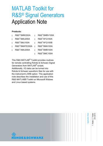
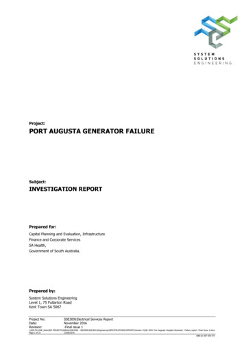
Signal Generator FundamentalsThe Complete Measurement SystemAn acquisition instrument — usually an oscilloscope or logicanalyzer — is probably the first thing that comes to mind whenyou think about making electronic measurements. But thesetools can only make a measurement when they are able toacquire a signal of some kind. And there are many instances inwhich no such signal is available unless it is externally provided.A strain gauge amplifier, for example, does not producesignals; it merely increases the power of the signals it receivesfrom a sensor. Similarly, a multiplexer on a digital address busdoes not originate signals; it directs signal traffic from counters,registers, and other elements. But inevitably it becomes necessary to test the amplifier or multiplexer before it is connectedto the circuit that feeds it. In order to use an acquisitioninstrument to measure the behavior of such devices, youmust provide a stimulus signal at the input.To cite another example, engineers must characterize theiremerging designs to ensure that the new hardware meetsdesign specifications across the full range of operation andbeyond. This is known as margin or limit testing. It is a measurement task that requires a complete solution; one that cangenerate signals as well as make measurements. The toolsetfor digital design characterization differs from its counterpartin analog/mixed signal design, but both must include stimulusinstruments and acquisition instruments.The signal generator, or signal source, is the stimulus sourcethat pairs with an acquisition instrument to create the twoelements of a complete measurement solution. The two toolsflank the input and output terminals of the device-under-test(DUT) as shown in Figure 1. In its various configurations, thesignal generator can provide stimulus signals in the form ofanalog waveforms, digital data patterns, modulation, intentionaldistortion, noise, and more. To make effective design, characterization, or troubleshooting measurements, it is important toconsider both elements of the solution.Figure 1. Most measurements require a solution made up of a signal generator pairedwith an acquisition instrument. Triggering connectivity simplifies capturing of the DUToutput signal.www.tektronix.com/signal generators5
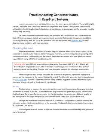
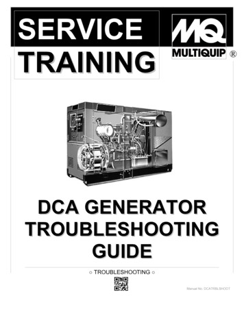
Signal Generator FundamentalsThe purpose of this document is to explain signal generators,their contribution to the measurement solution as a wholeand their applications. Understanding the many types ofsignal generators and their capabilities is essential to yourwork as a researcher, engineer or technician. Selecting theright tool will make your job easier and will help you producefast, reliable results.After reading this primer, you will be able to:Describe how signal generators workDescribe electrical waveform typesDescribe the differences between mixed signal generatorsand logic signal generatorsUnderstand basic signal generator controlsGenerate simple waveformsShould you need additional assistance, or have any commentsor questions about the material in this primer, simply contactyour Tektronix representative, or visit www.tektronix.com/signal generators.The Signal GeneratorThe signal generator is exactly what its name implies: a generator of signals used as a stimulus for electronic measurements.Most circuits require some type of input signal whose amplitudevaries over time. The signal may be a true bipolar AC1 signal(with peaks oscillating above and below a ground referencepoint) or it may vary over a range of DC offset voltages, eitherpositive or negative. It may be a sine wave or other analogfunction, a digital pulse, a binary pattern or a purely arbitrarywave shape.The signal generator can provide “ideal” waveforms or it mayadd known, repeatable amounts and types of distortion (or errors)to the signal it delivers. See Figure 2. This characteristic is oneof the signal generator’s greatest virtues, since it is often impossibleto create predictable distortion exactly when and where it’sneeded using only the circuit itself. The response of the DUT inthe presence of these distorted signals reveals its ability to handle stresses that fall outside the normal performance envelope.16www.tektronix.com/signal generatorsNormally, the term “AC” denotes a signal that goes positive and negative about a 0 volt(ground) reference and therefore reverses the direction of current flow once in every cycle. Forthe purposes of this discussion, however, AC is defined as any varying signal, irrespective ofits relationship to ground. For example, a signal that oscillates between 1 V and 3 V, eventhough it always draws current in the same direction, is construed as an AC waveform. Mostsignal generators can produce either ground-centered (true AC) or offset waveforms.
Signal Generator FundamentalsAnalog or Digital?Most signal generators today are based on digital technology. Manycan fulfill both analog and digital requirements, although themost efficient solution is usually a source whose features areoptimized for the application at hand — either analog or digital.Arbitrary waveform generators (AWG) and function generatorsare aimed primarily at analog and mixed-signal applications.These instruments use sampling techniques to build and modify waveforms of almost any imaginable shape. Typically thesegenerators have from 1 to 4 outputs. In some AWGs, thesemain sampled analog outputs are supplemented by separatemarker outputs (to aid triggering of external instruments) andsynchronous digital outputs that present sample-by-sampledata in digital form.Digital waveform generators (logic sources) encompass twoclasses of instruments. Pulse generators drive a stream of squarewaves or pulses from a small number of outputs, usually at veryhigh frequencies. These tools are most commonly used to exercisehigh-speed digital equipment. Pattern generators, also knownas data generators or data timing generators, typically provide 8,16, or even more synchronized digital pulse streams as a stimulussignal for computer buses, digital telecom elements, and more.Figure 2. (Top) Ideal waveform; (Bottom) “Real-world” waveform. A versatile signalgenerator can provide controlled distortions and aberrations for stress testing andcharacterization of devices.www.tektronix.com/signal generators7
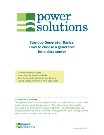
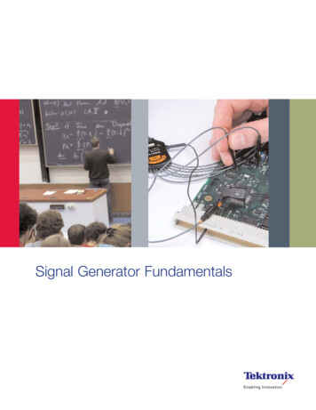
Signal Generator FundamentalsDUTOscilloscope/Logic AnalyzerTestPointGPIB/LANOutInCaptured WaveformSignalSourceOutputStandard orReference WaveformAdd ImpairmentsFigure 3. Signal generators can use standard, user-created or captured waveforms, adding impairments where necessary for special test applications.Basic Signal Generator ApplicationsSignal generators have hundreds of different applications butin the electronic measurement context they fall into three basiccategories: verification, characterization, and stress/margintesting. Some representative applications include:arbitrary waveform generators can provide the needed lowdistortion, high-resolution signals at rates up to 1 gigabit persecond (1 Gbps), with two independent channels, one for the“I” phase and one for the “Q” phase.VerificationSometimes the actual RF signal is needed to test a receiver. Inthis case, arbitrary waveform generators with sample rates upto 200 S/s can be used to directly synthesize the RF signal.Testing Digital Modular Transmitters and ReceiversCharacterizationWireless equipment designers developing new transmitter andreceiver hardware must simulate baseband I&Q signals — withand without impairments — to verify conformance with emergingand proprietary wireless standards. Some high-performanceTesting D/A and A/D Converters8www.tektronix.com/signal generatorsNewly-developed digital-to-analog converters (DAC) and analogto-digital converters (ADC) must be exhaustively tested todetermine their limits of linearity, monotonicity, and distortion.A state-of-the-art AWG can generate simultaneous, in-phaseanalog and digital signals to drive such devices at speeds upto 1 Gbps.
Signal Generator FundamentalsStress/Margin TestingSignal Generation TechniquesStressing Communication ReceiversThere are several ways to create waveforms with a signal generator. The choice of methods depends upon the informationavailable about the DUT and its input requirements; whetherthere is a need to add distortion or error signals, and othervariables. Modern high-performance signal generators offerat least three ways to develop waveforms:Engineers working with serial data stream architectures(commonly used in digital communications buses and diskdrive amplifiers) need to stress their devices with impairments,particularly jitter and timing violations. Advanced signal generatorssave the engineer untold hours of calculation by providing efficientbuilt-in jitter editing and generation tools. These instrumentscan shift critical signal edges as little as 200 fs (0.2 ps).Create: Brand new signals for circuit stimulus and testingReplicate: Synthesize an unavailable real-world signal(captured from an oscilloscope or logic analyzer)Generate: Ideal or stressed reference signals for industrystandards with specific toleranceswww.tektronix.com/signal generators9
Signal Generator FundamentalsUnderstanding WaveformsWaveform CharacteristicsThe term “wave” can be defined as a pattern of varying quantitative values that repeats over some interval of time. Wavesare common in nature: sound waves, brain waves, oceanwaves, light waves, voltage waves, and many more. All areperiodically repeating phenomena. Signal generators are usuallyconcerned with producing electrical (typically voltage) wavesthat repeat in a controllable manner.Each full repetition of a wave is known as a “cycle.” A waveformis a graphic representation of the wave’s activity — its variationover time. A voltage waveform is a classic Cartesian graphwith time on the horizontal axis and voltage on the verticalaxis. Note that some instruments can capture or producecurrent waveforms, power waveforms, or other alternatives.In this document we will concentrate on the conventionalvoltage vs. time waveform.Amplitude, Frequency, and PhaseWaveforms have many characteristics but their key propertiespertain to amplitude, frequency, and phase:Amplitude: A measure of the voltage “strength” of thewaveform. Amplitude is constantly changing in an ACsignal. Signal generators allow you to set a voltage range,for example, —3 to 3 volts. This will produce a signal thatfluctuates between the two voltage values, with the rateof change dependent upon both the wave shape andthe frequency.Frequency: The rate at which full waveform cycles occur.Frequency is measured in Hertz (Hz), formerly known ascycles per second. Frequency is inversely related to theperiod (or wavelength) of the waveform, which is a measureof the distance between two similar peaks on adjacentwaves. Higher frequencies have shorter periods.Phase: In theory, the placement of a waveform cyclerelative to a 0 degree point. In practice, phase is the timeplacement of a cycle relative to a reference waveform orpoint in time.10www.tektronix.com/signal generators90ºFigure 4. Phase shift (also known as delay), describes the difference in timing betweentwo signals. Phase is usually expressed in degrees as shown, but a time value may bemore appropriate in some circumstances.Phase is best explained by looking at a sine wave. The voltagelevel of sine waves is mathematically related to circular motion.Like a full circle, one cycle of a sine wave travels through 360degrees. The phase angle of a sine wave describes how muchof its period has elapsed.Two waveforms may have identical frequency and amplitude andstill differ in phase. Phase shift, also known as delay, describesthe difference in timing between two otherwise similar signals,as shown in Figure 4. Phase shifts are common in electronics.The amplitude, frequency, and phase characteristics of awaveform are the building blocks a signal generator uses tooptimize waveforms for almost any application. In addition,there are other parameters that further define signals, andthese too are implemented as controlled variables in manysignal generators.Rise and Fall TimeEdge transition times, also referred to as rise and fall times, arecharacteristics usually ascribed to pulses and square waves.They are measures of the time it takes the signal edge to makea transition from one state to another. In modern digital circuitry,these values are usually in the low nanosecond range or less.
Signal Generator FundamentalsPeriodPulse Width50% Amplitude10%90%90%RiseTime10%FallTimeFigure 5. Basic pulse characteristics.Both rise and fall times are measured between the 10% and90% points of the static voltage levels before and after thetransition (20% and 80% points are sometimes used asalternatives). Figure 5 illustrates a pulse and some of thecharacteristics associated with it. This is an image of thetype you would see on an oscilloscope set at a high samplerate relative to the frequency of the incoming signal. At alower sample rate, this same waveform would look muchmore “square.”In some cases, rise and fall times of generated pulses needto be varied independently, for example when using generatedpulses to measure an amplifier with unsymmetrical slew rates,or controlling the cool down time of a laser spot welding gun.Pulse WidthPulse width is the time that elapses between the leading andtrailing edges of a pulse. Note that the term “leading” appliesto either positive-going or negative-going edges as does theterm “trailing.” In other words, these terms denote the order inwhich the events occur during a given cycle; a pulse’s polaritydoes not affect its status as the leading or trailing edge. InFigure 5, the positive-going edge is the leading edge. Thepulse width measurement expressed the time between the50% amplitude points of the respective edges.OffsetGroundFigure 6. The offset voltage describes the DC component of a signal containing bothAC and DC values.Another term, “duty cycle,” is used to describe a pulse’s highand low (on/off) time intervals. The example in Figure 5 represents a 50% duty cycle. In contrast, a cycle with a period of100 ns whose active high (on) level lasts 60 ns is said to havea 60% duty cycle.To cite a tangible example of a duty cycle, imagine an actuatorthat must rest for three seconds after each one-second burstof activity, in order to prevent the motor from overheating. Theactuator rests for three seconds out of every four — a 25%duty cycle.www.tektronix.com/signal generators11
Signal Generator FundamentalsOffsetNot all signals have their amplitude variations centered ona ground (0 V) reference. The “offset” voltage is the voltagebetween circuit ground and the center of the signal’s amplitude.In effect, the offset voltage expresses the DC component of asignal containing both AC and DC values, as shown in Figure 6.Single-EndedDevice OutputDifferential vs. Single-ended SignalsDifferential signals are those that use two complementarypaths carrying copies of the same signal in equal and oppositepolarity (relative to ground). As the signal’s cycle proceeds andthe one path becomes more positive, the other becomes morenegative to the same degree. For example, if the signal’s valueat some instant in time was 1.5 volts on one of the paths,then the value on the other path would be exactly -1.5 volts(assuming the two signals were perfectly in phase). Thedifferential architecture is good at rejecting crosstalk andnoise and passing only the valid signal.Single-ended operation is a more common architecture, inwhich there is only one path plus ground. Figure 7 illustratesboth single-ended and differential approaches.12www.tektronix.com/signal generatorsDifferentialDevice OutputFigure 7. Single-ended and differential signals.
Signal Generator FundamentalsSine WaveDamped Sine WaveSquare WaveRectangular WaveFigure 8. Sine and damped sine waves.Figure 9. Square and rectangular waves.Basic WavesThe damped sine wave is a special case in which a circuitoscillates from an impulse, and then winds down over time.Waveforms come in many shapes and forms. Most electronicmeasurements use one or more of the following wave shapes,often with noise or distortion added:Figure 8 shows examples of sine and damped sine wavederived signals.Sine wavesSquare And Rectangular WavesSquare and rectangular wavesSquare and rectangular waves are basic forms that are atthe heart of all digital electronics, and they have other usesas well. A square wave is a voltage that switches betweentwo fixed voltage levels at equal intervals. It is routinely usedto test amplifiers, which should be able to reproduce the fasttransitions between the two voltage levels (these are the riseand fall times explained earlier). The square wave makes anideal timekeeping clock for digital systems — computers,wireless telecom equipment, HDTV systems, and more.Sawtooth and triangle wavesStep and pulse shapesComplex wavesSine WavesSine waves are perhaps the most recognizable wave shape.Most AC power sources produce sine waves. Household walloutlets deliver power in the form of sine waves. And the sinewave is almost always used in elementary classroom demonstrations of electrical and electronic principles. The sine waveis the result of a basic mathematical function — graphing asine curve through 360 degrees will produce a definitive sinewave image.A rectangular wave has switching characteristics similar tothose of a square wave, except that its high and low timeintervals are not of equal length, as described in the earlier“duty cycle” explanation. Figure 9 shows examples of squareand rectangular waves.www.tektronix.com/signal generators13
Signal Generator FundamentalsSawtooth WaveTriangle WaveFigure 10. Sawtooth and triangle waves.Sawtooth and Triangle WavesSawtooth and triangle waves look very much like the geometricshapes they are named for. The sawtooth ramps up slowlyand evenly to a peak in each cycle, then falls off quickly. Thetriangle has more symmetrical rise and fall times. These waveforms are often used to control other voltages in systems suchas analog oscilloscopes and televisions. Figure 10 showsexamples of sawtooth and triangle waves.Step and Pulse ShapesA “step” is simply a waveform that shows a sudden changein voltage, as though a power switch had been turned on.The “pulse” is related to the rectangular wave. Like the rectangle, it is produced by switching up and then down, or downand then up, between two fixed voltage levels. Pulses areinherently binary and therefore are the basic tool for carrying14www.tektronix.com/signal generatorsStepPulsePulse TrainFigure 11. Step, pulse, and pulse train shapes.information (data) in digital systems. A pulse might representone bit of information traveling through a computer. A collectionof pulses traveling together creates a pulse train. A synchronized group of pulse trains (which may be transmitted inparallel or serial fashion) makes up a digital pattern. Figure 11shows examples of step and pulse shapes and a pulse train.Note that, while digital data is nominally made up of pulses,rectangles, and square waves, real-world digital waveformsexhibit more rounded corners and slanted edges.Sometimes, circuit anomalies produce pulses spontaneously.Usually these transient signals occur non-periodically, andhave come to be described with the term “glitch.” One of thechallenges of digital troubleshooting is distinguishing glitchpulses from valid but narrow data pulses. And one of thestrengths of certain types of signal generators is their abilityto add glitches anywhere in a pulse train.
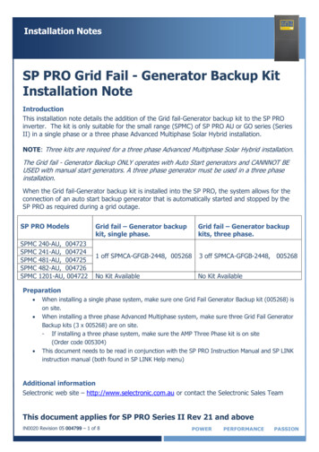
Signal Generator FundamentalsFigure 12. Amplitude modulation.Complex WavesIn operational electronic systems, waveforms rarely look likethe textbook examples explained above. Certain clock andcarrier signals are pure, but most other waveforms will exhibitsome unintended distortion (a by-product of circuit realities likedistributed capacitance, crosstalk, and more) or deliberatemodulation. Some waveforms may even include elements ofsines, squares, steps, and pulses.Complex waves include:Analog modulated, digitally modulated, pulse-widthmodulated, and quadrature modulated signalsDigital patterns and formatsPseudo-random bit and word streamsSignal ModulationIn modulated signals, amplitude, phase and/or frequencyvariations embed lower-frequency information into a carriersignal of higher frequency. The resulting signals may conveyanything from speech to data to video. The waveforms canbe a challenge to reproduce unless the signal generator isspecifically equipped to do so.Figure 13. Frequency-shift keying (FSK) Modulation.Analog Modulation. Amplitude modulation (AM) and frequencymodulation (FM) are most commonly used in broadcastcommunications. The modulating signal varies the carrier’samplitude and/or frequency. At the receiving end, demodulatingcircuits interpret the amplitude and/or frequency variations,and extract the content from the carrier.Phase modulation (PM) modulates the phase rather thanthe frequency of the carrier waveform to embed the content.Figure 12 illustrates an example of analog modulation.Digital Modulation. Digital modulation, like other digitaltechnologies, is based on two states which allow the signalto express binary data. In amplitude-shift keying (ASK), thedigital modulating signal causes the output frequency toswitch between two amplitudes; in frequency-shift keying(FSK), the carrier switches between two frequencies (its centerfrequency and an offset frequency); and in phase-shift keying(PSK), the carrier switches between two phase settings. InPSK, a “0” is imparted by sending a signal of the same phaseas the previous signal, while a “1” bit is represented by sendinga signal of the opposite phase.Pulse-width modulation (PWM) is yet another common digitalformat; it is often used in digital audio systems. As its nameimplies, it is applicable to pulse waveforms only. With PWM,the modulating signal causes the active pulse width (dutycycle, explained earlier) of the pulse to vary.Figure 13 shows an example of digital modulation.www.tektronix.com/signal generators15
Signal Generator FundamentalsFigure 14. Frequency sweep of sine wave.Frequency SweepMeasuring the frequency characteristics of an electronicdevice calls for a “swept” sine wave — one that changes infrequency over a period of time. The frequency change occurslinearly in “Hz per seconds” or logarithmically in “Octavesper second.” Advanced sweep generators support sweepsequences with selectable start frequency, hold frequency,stop frequency and associated times. The signal generatoralso provides a trigger signal synchronously to the sweep tocontrol an oscilloscope that measures the output responseof the device.Quadrature Modulation. Today’s digital wireless communicationsnetworks are built on a foundation of quadrature (IQ) modulationtechnology. Two carriers — an in-phase (I) waveform and aquadrature-phase (Q) waveform that is delayed by exactly 90degrees relative to the “I” waveform — are modulated to producefour states of information. The two carriers are combined andtransmitted over one channel, then separated and demodulatedat the receiving end. The IQ format delivers far more informationthan other forms of analog and digital modulation: it increasesthe effective bandwidth of the system. Figure 15 depictsquadrature modulation.Digital Patterns and FormatsA digital pattern consists of multiple synchronized pulsestreams that make up “words” of data that may be 8, 12, 16,or more bits wide. One class of signal generator, the digital patterngenerator, specializes in delivering words of data to digitalbuses and processors via parallel outputs. The words in thesepatterns are transmitted in a steady march of cycles, with theactivity for each bit in each cycle determined by the chosensignal format. The formats affect the width of the pulses withinthe cycles that compose the data streams.16www.tektronix.com/signal generatorsFigure 15. Quadrature modulation.The following list summarizes the most common signalformats. The first three format explanations assume thatthe cycle begins with a binary “0” value – that is, a low logicvoltage level.Non-Return-to-Zero (NRZ): When a valid bit occurs in thecycle, the waveform switches to a “1” and stays at thatvalue until the next cycle boundary.Delayed Non-Return-to-Zero (DNRZ): Similar to NRZ,except that the waveform switches to a “1” after a specifieddelay time.Return-to-Zero (RZ): When a valid bit is present, thew
right tool will make your job easier and will help you produce fast, reliable results. After reading this primer, you will be able to: Describe how signal generators work Describe electrical waveform types Describe the differences between mixed signal generators and logic signal generators Understand basic signal generator controls