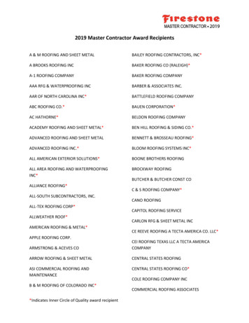
Transcription
Roofing Installation Manual: Concealed Fastener PanelsMaterial Data, Trim Details, and Step-by-Step Instructions1974 Livengood AveFairbanks, AK 99701907-479-6002allsteel.info@gmail.com
Roof Installation GuideConcealed Fastener PanelsNOTES TO INSTALLER2RECOMMENDED TOOLS & EQUIPMENT3PANEL DATA4FASTENING9HOW TO BEGIN11ORDER OF INSTALLATION12HOW TO SQUARE YOUR ROOF13TRIM DETAILS14CHIMNEY & SKYLIGHT DETAILS211
NOTES TO INSTALLERTHIS INSTALLATION GUIDE IS INTENDED TO BE AN AID AND DOES NOT DEPICT ALL SITUATIONS.MODIFICATIONS ARE THE RESPONSIBILITY OF THE DESIGNER/USER AND SHOULD TAKE INTOCONSIDERATION THE CLIMATE, WIND AND SNOW LOAD CONDITIONS. WHERE POSSIBLE, PANELSSHOULD BE LAPPED AWAY FROM PREVAILING WIND.SubstratesThe details shown in this guide depict the roofing being installed over 5/8” plywood with a waterproof membraneapplied to it. All of these panels can be installed over spaced support members. Consult an All Steel Inc.representative for more information.Minimum Slope RequirementsAll panels in this guide require a 1:12 or greater roof pitch, unless stated otherwise.UnderlaymentsBefore panel installation, a minimum of 30 lb. felt should be installed per manufacturer’s recommendations.Underlayment is to be lapped in a manner so it will shed water. Where more protection is required (in valleys, aroundchimneys, skylights, and below pitch changes), use a self-adhering cold-applied rubberized asphalt membrane.Granulated ice & water shield is not acceptable.Oil-CanningFlat surfaces in the panels will commonly display waviness referred to as “oil-canning”. This is caused by the steelmill tolerances of the material and variations in the substrate and roofing underlayment. Oil-canning is acharacteristic, not a defect of panels manufactured from light gauge metal. Panels are factory quality checked andcorrected prior to manufacturing your order.WarrantyAll Steel Inc. offers a 20 year transferrable paint warranty on all SMP Paint System products (26, 29 gauge panels).All Steel Inc. offers a 25 year transferrable paint warranty on all PVDF / Kynar Paint System products (22, 24 gaugepanels).2
RECOMMENDED TOOLS & EQUIPMENTScrew GunsAdjustable clutch type screw guns are recommended for screws with gasketed sealing washers to prevent over- orunder-tightening of screws. Impact type screw guns are great for all blind fasteners and can also be used ongasketed fasteners with much attention paid to tightness of fastener.Drill Bits and Driver Bits1/8” DRILL BIT7/32” DRILL BIT1/4” DRILL BIT5/16 DRIVER BIT1/4” DRIVER BIT#2 & #3 PHILIPS DRIVER BIT#2 SQ DRIVER BITCutting ToolsTIN SNIPS – green and red offset snips will provide the widest range of straight and left to right finish cutting.ELECTRIC/AIR SHEARS – good for blind cuts and ripping panels length ways.CIRCULAR SAWS – when equipped with a sharp carbide blade designed for cutting steel, a circular saw will workbest for cutting panels across their width. For instance, when cutting gable ends and valley angles. WARNING – useof abrasive cutting blades is not recommended; they can overheat the metal and cause the paint to peel away fromthe metal. If panels are to be cut, or pre-drilled, be certain to wipe free any metal chips that have accumulated on thepanel.Other ToolsPOP RIVET TOOL – used for miscellaneous fastening of trim and flashing details.FOLDING TOOLS – these can be either locking or pressure clamping. Used mainly for bending blind tabs on trim.STRINGS and CHALK LINES – used to assist in the alignment of panels and trim.RUBBER MALLET – used for snap seam panels.HAND CRIMPER and ELECTRIC SEAMER – used for mechanically seamed panels.3
PANEL DATAALL STEEL’s 29 and 26 gauge panels are finished with a high-performance baked-on silicone-modified polyester(SMP) paint system on an AZ50 substrate.This cutting edge resin technology offers unbeatable durability, superior color retention and resistance to dirtaccumulation, ensuring low maintenance, lasting beauty and outstanding value.ALL STEEL’s 24 and 22 gauge panels are finished with a specialized Polyvinylidene Flouride (PVDF) / Kynar paintsystem on an AZ50 substrate.PVDF paints are developed using ceramic pigments combined with fluoropolymer resins to create high end coatingsfor metals. PVDF pre-painted steel has been the go-to product for architects and designers around the world toachieve beautiful, vibrant colors with the added benefits of flexibility, durability, and low maintenance. PVDF prepainted steel is best suited for high-end applications such as commercial or residential roofing, pre-engineeredbuildings, architectural wall panels, and other applications where durability and long-lasting performance are required.ALL STEEL INC. follows the national A.I.S.I. (American Iron and Steel Institute) specifications manual for tolerancesin galvanized sheet metal.4
WeightGaugeGradePaint1" Snap Seam - 16"1" Snap Seam - 12"2680SMP1.57 lb/LF118 lb/SQ1.26 lb/LF126 lb/SQ2450Kynar2.00 lb/LF150 lb/SQ1.61 lb/LF161 lb/SQ1" Snap Seam - 16" - 26 GASubstrateWind Uplift Load (Internal Pressure) psfFastener9"12"1/2" Plywood#10 x 1" Pan Head80605/8" Plywood#10 x 1" Pan Head115.786.87/16" OSB#10 x 1" Pan Head57.142.8Steel Yield Stress: 26 GA 80,000 psi, 24 GA 50,000 psiGalvanized Steel Gauge, AZ-501 ½” Bearing LengthLoad Span Tables Based on Working Stress.Flexural Design analysis according to AISI “Specification for the Design of Light Gauge Cold-Formed Steel StructuralMembers” May 1981.Continuous Span Loading applies to sheets continuous over three or more spans.Weight of sheet has not been allowed for when calculating live load and uplift.Deflection (L/180) limiting live load based on deflection of span.Metal thickness based on minimum ASTM specifications for allowable load calculations.Note: The load tables have been compiled for the design of steel roofing and siding used in conjunction with eitherwood or steel framed structures. ALL STEEL INC. assumes no responsibility, either expressed or implied, for its use.All gauges conform to ASTM A446 Grade E (80,000 min. yield) unless otherwise designated at time of order.5
WeightGaugeGradePaint2450Kynar1.75" Thin Seam - 16"Span (ft)1.75" Thin Seam - 16"2.10 lb/LF158 lb/SQLive Load (Strength) psf2.5'3'3.5'4'5'16611585654224 GA - 2 span14510174573624 GA - 3 span18112692714524 GA - 4 span169117866642Span (ft)1.72 lb/LF172 lb/SQWind Uplift Load (Internal Pressure) psf24 GA - single1.75" Thin Seam - 12"1.75" Thin Seam - 12"Live Load (Strength) psf2'2.5'3'3.5'4'8774615855Wind Uplift Load (Internal Pressure) psf2.5'3'3.5'4'5'24 GA - single200151111855524 GA - 2 span19113397754824 GA - 3 span200166122936024 GA - 4 span20015511487562'2.5'3'3.5'4'1401191049694Steel Yield Stress: 50,000 psiGalvanized Steel Gauge, AZ-501 ½” Bearing LengthLoad Span Tables Based on Working Stress.Continuous Span Loading applies to sheets continuous over three or more spans.Weight of sheet has not been allowed for when calculating live load and uplift.Deflection (L/180) limiting live load based on deflection of span.Metal thickness based on minimum ASTM specifications for allowable load calculations.Wind Uplift Loads in accordance to ASTM E-1592. Use factor of safety for Design Loads.Note: The load tables have been compiled for the design of steel roofing and siding used in conjunction with eitherwood or steel framed structures. ALL STEEL INC. assumes no responsibility, either expressed or implied, for its use.All gauges conform to ASTM A446 Grade E (80,000 min. yield) unless otherwise designated at time of order.6
WeightGaugeGradePaint2450Kynar2.13 lb/LF160 lb/SQ1.75 lb/LF175 lb/SQ2250Kynar2.59 lb/LF194 lb/SQ2.12 lb/LF212 lb/SQ2" Mech. Seam - 16"Span (ft)2" Mech. Seam - 16"Live Load (Strength) psfWind Uplift Load (Internal Pressure) psf2.5'3'3.5'4'4.5'24 GA simple span1621351161138924 GA continuous span162135116897122 GA simple span23319516715112022 GA continuous span2331951671291022" Mech. Seam - 12"Span (ft)2" Mech. Seam - 12"Live Load (Strength) psf2'2.5'3'4'5'113998468531361241118966Wind Uplift Load (Internal Pressure) psf2.5'3'3.5'4'4.5'24 GA simple span21618015414511524 GA continuous span2161801531179222 GA simple span31126023719215222 GA continuous 13810980Steel Yield Stress: 50,000 psiGalvanized Steel Gauge, AZ-501 ½” Bearing LengthLoad Span Tables Based on Working Stress.Continuous Span Loading applies to sheets continuous over three or more spans.Weight of sheet has not been allowed for when calculating live load and uplift.Deflection (L/180) limiting live load based on deflection of span.Metal thickness based on minimum ASTM specifications for allowable load calculations.Wind Uplift Loads in accordance to ASTM E-1592. Use factor of safety for Design Loads.Note: The load tables have been compiled for the design of steel roofing and siding used in conjunction with eitherwood or steel framed structures. ALL STEEL INC. assumes no responsibility, either expressed or implied, for its use.All gauges conform to ASTM A446 Grade E (80,000 min. yield) unless otherwise designated at time of order.7
Wind Uplift:Steel roofing panels provide superior uplift resistance to wind loads and are the go-to design choice for sloped roofsin high-wind regions. Wind uplift design requirements are dependent on roof Height, Exposure category, Importanceclassification, and Basic Wind Speed for the building location (basic wind speeds in Alaska range from 90 mph in theInterior to 130 mph in some Coastal areas). For example, a residence in Fairbanks, with a generalized structureheight of 30 ft., must be designed to meet wind uplift loads of at least 27 psf. Uplift loads for Alaska’s basic windspeeds are shown in the following table:Wind Speed(mph)Uplift Load*(psf)902710032110391204613054*Based on SEI/ACSE 7-02 standard for low slope roofs, generalized 30’ Height at roof edge, Exposure B (urban,suburban, wooded areas), Importance Classification II (residential, light commercial).Areas of discontinuity are subjectto higher spikes in windpressure; building geometry willeffect aerodynamic pressures atedges and corners of the roof.This figure illustrates theimportance of properly fasteningeave, gable, and ridge flashings.Negative values indicate suctionpressure acting upward. Loadsbased on 90 mph basic windspeed, exposure B, importanceclassification II, and 30’ roofheight.8
FASTENINGScrew fasteners have been proved to have two to three times the holding power of nails. Screws should have aminimum penetration of 5/8" into wood. Generally, #10 x 1" Pancake Head screw fasteners are used for concealedfastener panels. 1” Snap Seam panels are fastened through pre-punched slots in the lower lap screw flange. 1.75”Thin Seam and 2” Mechanical Seam panels are attached with their respective clips, 2 screws per clip. Bearing platesare used under clips when installing panels over rigid insulation.Nails are not recommended!The use of nails to fasten panels is NOT recommended and will void any warranty.DO NOTOVERDRIVEexposed fasteners soas to dimple or distortthe panelaccessories.Washers should be infirm contact with thepanel.9
1" Snap SeamSlotted Panel1.75" Thin SeamClipBearing PlateClipBearing Plate2" Mech. Seam10
HOW TO BEGIN Determine quantity and length of panels needed. Determine quantity and type of flashings and accessories. Pitch of the roof(s) must be known in order to fabricate trim and flashings. For roof purlin spacing, refer to Load Tables for the panel you are planning to install and Maximum FastenerRow Spacing in the Panel and Screw Data sections. Install underlayment over OSB applications. Determine prevailing wind direction. Roofing panels should be installed beginning at the opposite end of thebuilding from the prevailing wind direction. For proper lapping of roof panels and other trim details, see drawings in Panel Data and Trim Detailsections. The Trim Details in this guide refer to the 1.75” Thin Seam Panel. Trims for other concealedfastener panels will differ slightly in dimension to accommodate respective rib heights.11
ORDER OF INSTALLTION1)Eave or Drip Edge flashing2)Underlayment3)Valley or Prow flashing4)Upper Skylight or Chimney flashing5)Roofing Panels6)Plumbing flashers7)Gable Caps, Sidewall, Closure Strips, Headwall, and Ridge Cap8)Sides and bottom flashing of Skylight or ChimneyPANEL-SPECIFIC INSTALLATION NOTES1” Snap Seam: Low-slope applications require sealant applied at seams. May not be end-lapped.1.75” Thin Seam: Use bearing plates when installing over rigid insulation. May not be end-lapped.2” Mechanical Seam: Use bearing plates when installing over rigid insulation. When installing less than full-length panels, end-lap each panel from eave to ridge before installing the nextrow of panels. Panels must be hand crimped at each clip and end-lap as they are installed to prevent their separation by astrong wind. Panels should be seamed with electric seaming tool as soon as possible after installation.12
HOW TO SQUARE YOUR ROOFThe best method to square up your roofing panels is the 3-4-5 triangle method. A 3’x4’x5’ triangle works in smallerroof areas. In larger areas, use multiples of 3’x4’x5’ to increase the size of your triangle to more precisely square uplonger panels.NOTE: ALWAYS SQUARE FOM THE EAVE1)Measure in from the gable 1”-3” and make a mark about 6” from the eave.2)Measure 4’ (or multiple of 4’) farther into the roof from the gable and make a mark the same distance (6”) upfrom the eave.3)From the first mark, measure up the roof 3’ (or same multiple of 3’ that was used to make the 4’ multiple)and make a small arc-shaped mark (about 4”-6” long).4)From the second mark made along the eave, measure 5’ (or same multiple) diagonally back up towards thegable to the first arc, and make a second small intersecting arc. The intersection of the two arcs is the thirdpoint of the squared 3-4-5 triangle.5)Snap a chalk line up the vertical side of the 3-4-5 triangle. This line will be parallel to the length of the roofpanels and will help locate the first panel squarely with the EAVE of the roof. Subsequent vertical lines canbe created from the first in order to keep the rest of the panels square with the eave.13
VALLEY FLASHING13 4"10"13 4"10"1.75" THINSEAM PANELSEALANT INRIB SEAMS#10X1" PANHEAD SCREWS2 PER CLIP#14X1" SCREWSEVERY 6" OR ASNEEDEDTHIN SEAMPANEL CLIPPLYWOOD 5 8"MINIMUMWATER PROOFUNDERLAYMENTSEALANTTAPE14
EVE FLASHING#10X1" PANHEAD SCREWS2 PER CLIP1.75" THINSEAM PANELSEALANT INRIB SEAMSWATER PROOFUNDERLAYMENTTHIN SEAMPANEL CLIPPLYWOOD 5 8"MINIMUMSEALANTTAPE#14X1" SCREWSEVERY 24" OR ASNEEDED23 4"2"1 "215
1.75" THIN SEAM PANEL RIDGE CAP41 4"41 4"11 2"112"1 "21 "21.75" THINSEAM PANELWATER PROOFUNDERLAYMENTZ CLOSURE#12X3 4" SCREWSEVERY 24" OR ASNEEDED#10X1" PANHEAD SCREWS2 PER CLIP#14X1" SCREWSEVERY 24" OR ASNEEDEDSEALANTTHIN SEAMPANEL CLIPPLYWOOD 5 8"MINIMUM16
1.75" THIN SEAM PANEL GABLE CAP3"11 2"17 8"4"1.75" THINSEAM PANELWATER PROOFUNDERLAYMENTSEALANTPLYWOOD 5 8"MINIMUM#14X1" SCREWSEVERY 24" OR ASNEEDED17
1.75" THIN SEAM PANEL HEADWALL31 2"6"#12X3 4" SCREWSEVERY 24" OR ASNEEDEDTHIN SEAMPANEL CLIP1.75" THINSEAM PANEL#10X1" PANHEAD SCREWS2 PER CLIPSEALANTWATER PROOFUNDERLAYMENT#14X1" SCREWSEVERY 24" OR ASNEEDEDPLYWOOD 5 8"MINIMUM18
1.75" THIN SEAM PANEL SHED RIDGE7"45 8"5 "8THIN SEAMPANEL CLIP#10X1" PANHEAD SCREWS2 PER CLIP#12X3 4" SCREWSEVERY 24" OR ASNEEDED1.75" THINSEAM PANELSEALANT#14X1" SCREWSEVERY 24" OR ASNEEDEDWATER PROOFUNDERLAYMENTPLYWOOD 5 8"MINIMUM19
1.75" THIN SEAM PANEL SIDEWALL3"3 "4218"2"#14X1" SCREWSEVERY 24" OR ASNEEDEDSEALANTWATER PROOFUNDERLAYMENT1.75" THINSEAM PANELPLYWOOD 5 8"MINIMUM20
CHIMNEY & SKYLIGHT FLASHINGInstallation of a chimney or skylight requires layering flashing to provide a weather tight roof. The following stepsillustrate one way to flash a chimney or skylight. Job site conditions may require alternate dimensions or installationtechniques. Required Skylight Flashing: 1ea. backpan flashing 2ea. sidewall flashing 1ea. endwall flashingSidewallEndwallPrior to trim installation, cut the roofing panels as close as possible to the left, right and downhill sides of the curb.Cut the uphill side panels 6" up from the curb. Do not fasten down the panels within 18" uphill from the skylight.Step #1Install panels around chimney or skylight, leaving out panels above. Where the panels running into the skylight aredeeper than needed, cut the panel opening 1" deeper than necessary (see Last Panel Termination Detail) and bendup creating false rib. Do not install panels directly above skylight.21
Step #2Install backpan flashing above skylight. When cutting to fit, leave a minimum of 4" to either side, wider thanthe skylight. Install panels above skylight, when cutting panels leave 6"-8"short of skylight. Apply sealantunder panels where the panels lap the backpan flashing. Continue paneling past skylight.Trim to widthof skylightplus 4" oneach side4" wider than skylight on both sidesStep #3Install endwall at the downhill side of the skylight. Cut the flashing to the width of the skylight plus 2" oneach side (sidewall typically 2" wide). Then cut back along the bend 2" on each side and bend the metalaround the curb.Bend metalaround skylightcurbCut back alongbend2" wider than skylight on both sides22
Step #4Install sidewall flashing by cutting back the top leg a minimum of 2” and folding around front of curb. Do this for bothsides of the skylight.23
Roofing Installation Manual: Concealed Fastener Panels . 1974 Livengood Ave . Fairbanks, AK 99701 . 907-479-6002 . allsteel.info@gmail.com Material Data, Trim Details, and Step-by-Step Instructions