Transcription
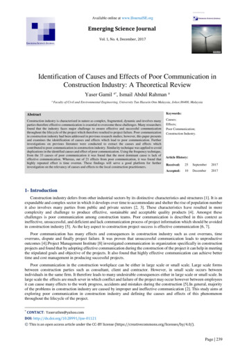
Designed, Manufactured and Supported in the USAVIKINGSECURITY & COMMUNICATION1600A SeriesPRODUCTMANUALADA CompliantEmergency PhonesJanuary 20, 2021ADA* Compliant Emergency Phones withBuilt-In Digital Voice AnnouncerThe 1600A Series ADA Compliant Emergency Phones are designed to provide quickand reliable handsfree communication for any standard analog telephone line or analogphone system station port. All 1600A Series phones meet ADA requirements forelevator/ emergency telephones, and can be programmed from any touch tone phone.The phones can dial up to 5 programmable emergency numbers, as well as 2 centralstation numbers. In addition, the E-1600-20A and E-1600-52A feature a second "INFO"button that will dial up to 3 non-emergency numbers.The 1600A Series phones can be programmed to automatically deliver a digitalannouncement to identify the location of the emergency call. Alternatively, a DTMF touchtone code may also be delivered. A “Call Connected” LED can be initiated manually orautomatically. All programming parameters, including phone numbers and locationnumbers, are stored in non-volatile memory. All units are phone line powered, requiringno batteries or external power and are compatible with common Central StationMonitoring equipment.For outdoor installations where the unit is exposed to precipitation or condensation, select1600A Series phones are available with Enhanced Weather Protection (EWP). EWPproducts are designed to meet IP66 standards and may feature foam rubber gaskets,sealed connections, gel-filled butt connectors, as well as potted circuit boards withinternally sealed, field-adjustable trim pots and DIP switches for easy onsiteprogramming. For more information on EWP, see DOD 859.Features Automatic Noise Canceling (ANC) feature for clear audio in noisy environments Meets the latest ASME A17.1 code when used with the optional LV-1K Line VerificationPanel, see DOD 246 Meets ADA requirements for Emergency Phones:- Automatically lights the “Call Connected” LED- Transmits a unique location I.D. code or voice announcement- Grade 2 Braille label for the visually impaired Non-volatile digital voice announcer with 16 seconds of voice memory Advanced call progress detection Handsfree operation Phone line powered Non-volatile memory (no batteries required) Marine grade 316 stainless steel prevents corrosion on stainless models Dials up to 5 emergency numbers E-1600-20A and E-1600-52A dial up to 3 non-emergency “INFO” numbers Cycles through backup phone numbers on busy or no-answer Optional Enhanced Weather Protection (EWP), EWP products are designed to meetIP66 Ingress Protection Rating, see DOD 859 Hangs up on CPC, silence, busy signal, dial tone, time-out or touch tone command Programmable to auto-answer on incoming calls Remotely programmable Extended temperature range (-15 F to 130 F) 16 different chassis or board only available Available in 42” tall tower phone model E-1600A-BLT-EWP (DOD 217) Central Station Monitoring capability (dials 2 numbers) Optional PB-100 Polling System available (DOD 232) Optional BLK-4-EWP strobe light kit available (DOD 654) Optional LC-6 Six Port Concentrator available (DOD 245) Optional LV-1K Line Verification Panel available (DOD 246) Optional E-1600A-MK-GNP Pedestal Mounting Kit (DOD 227) Optional PB-1 Panic Button Kit (DOD 233) Also available with VoIP interface, see DOD 255 for more -1600-55AE-1600-02AK-1600-EHFAApplications EntrywaysElevators Campus emergency stationsParking ramps/lots Roadside emergency stationsEmergency pool phones StadiumsATM machines Convention centersArea of refuge locationsLobbiesSilent holdup alarm dialer using optional Panic Button Kit* Americans with Disabilities Act of 1992 contains federal regulationsregarding elevator telephones (Public Law 101-336).www.VikingElectronics.comInformation: 715-386-8861SpecificationsPower: Telephone line powered. Minimum 24V DC talk battery voltage, witha minimum loop current of 20mA loop. Loop current may be boosted on lowcurrent lines with a Viking model TBB-1B Talk Battery Booster (DOD 632).Dimensions: See Installation and SpecificationsOperating Temperature: -15 F to 130 F (-26 C to 54 C)Humidity - Standard Products: 5% to 95% non-condensingHumidity - EWP Products: Up to 100%CAUTION - When installing on an analog extension of a phone system:Some phone systems do not conform to analog telecom standards and mightnot be compatible with the 1600A Series emergency phones. For a detaileddescription of the telephone line specifications required for any of the 1600ASeries phones, see DOD 869.
WiringIMPORTANT: Electronic devices are susceptible to lightning and power station electrical surges from both the ACoutlet and the telephone line. It is recommended that a surge protector be installed to protect against such surges.**** AnalogPABX/KSU StationC.O. LineRear View of a 1600A Series Phone*** Gel-Filled ButtConnectors-OR-RingTerminal(included)RedGreen** EarthGround(optional)* Drip Loop* Note: When wires are routed from above, a “drip loop” isrecommended to keep water away from the circuit board.** Note: To increase surge protection, loosen the PCBmounting screw labeled(as shown) and fasten awire with ring terminal (included) from the mountingscrew to Earth Ground (grounding rod, water pipe, etc.)*** Note: The gel-filled (water-tight) butt connectors are designed for insulation displacement on 19-26gauge wire with a maximum insulation of 0.082 inches. Cut off bare wire ends prior to terminating.**** Note: When installing a line powered phone on a low voltage and/or low loop current phone systemextension, a TBB-1B Talk Battery Booster may be required, see DOD 632 for more info.Installation and SpecificationsThe following sections show specifications and installation instructions for the different chassis in the 1600A Series.IMPORTANT: Electronic devices are susceptible to lightning and power station electrical surges from both the ACoutlet and the telephone line. It is recommended that a surge protector be installed to protect against such surges.E-1600A / E-1600-40A / E-1600-45A / E-1600-60A / E-1600-65ADimensions: 5.25” x 4.0” x 2.0” (133 mm x 102 mm x 51 mm)Shipping Weight: 2.5 lbs (1.13 kg)Material: 0.062” thick (16 gauge) steelFinish: E-1600A - Red powder paintE-1600-40A - Red powder paint, no “EMERGENCY PHONE” verbiageE-1600-45A - Yellow powder paintE-1600-60A - Blue powder paint with “POLICE” verbiageE-1600-65A - Blue powder paintConnections: Gel-filled butt connectorsMounting: Surface mount to walls, posts, single gang boxes or 4” x 4” electrical junction boxes,or recess mount in elevator phone boxes. Attach the mounting plate in desired location andconnect the wires. Then, secure the phone to the mounting plate with the provided set screw.POLICE4.00on model E-1600-60A onlyEMERGENCYPHONE3/4" knockout2.00Optional Enhanced Weather Protection (EWP) Available: EWP productsare designed to meet IP66 standards and may feature foam rubber gaskets,sealed connections, gel-filled butt connectors, as well as potted circuit boardswith internally sealed, field-adjustable trim pots and DIP switches for easyonsite programming. For more info on EWP, see DOD 859.Note: For greater weather resistance, apply a bead of clear silicon caulkingaround the top edge and sides of the chassis.Optional Gooseneck Pedestal Mounting Kit: The E-1600A-MK-GNPMounting Kit (DOD 227) allows you to mount the E-1600A, E-1600-40A,E-1600-45A, E-1600-60A or E-1600-65A to a Viking VE-GNP GooseneckPedestal (DOD 424).2.003.40SIDEVIEWMOUNTING NNECTEDPUSH FORHELPVIKING FRONT VIEWRed CallConnectedLEDPush to CallButtonGrade 2Braille Label3.30SetScrewCondensationDrain Hole(4) .20 dia.mountingholes1.70Model E-1600-45A has"EMERGENCY" verticallydown the side. ModelE-1600-60A has "POLICE"vertically down the side.(2) .20 x .40slots for singlegang box1.700.15 x 0.31Wire Exit Notch2Model E-1600Ashown withoptional VE-GNPpedestal andE-1600A-MK-GNPmounting kit.3.82
E-1600-SSA / E-1600-RDA / E-1600-YLA / E-1600-BLA / E-1600-BLPA / E-1600-BKAConnections: Gel-filled butt connectorsMounting: Surface mount to walls, posts or single gang electrical boxes. Attach themounting plate in desired location and connect the wires. Then, secure the phone tothe mounting plate with provided 8-32 set screws.Optional Enhanced Weather Protection (EWP) Available: EWP products are designedto meet IP66 standards and may feature foam rubber gaskets, sealed connections, gel-filledbutt connectors, as well as potted circuit boards with internally sealed, field-adjustable trimpots and DIP switches for easy onsite programming. For more info on EWP, see DOD 859.Note: For greater weather resistance, apply a bead of clear silicon caulking around thetop edge and sides of the chassis.Dimensions: 5.75” x 3.08” x 1.05” (146 mm x 78 mm x 27 mm)Shipping Weight: 2.5 lbs (1.3 kg)Material / Finish E-1600-SSA only: 0.060” thick (16 gauge) marine grade 316stainless steel with a #4 brushed finishMaterial: 0.060” thick (16 gauge) 304 stainless steelFinish: E-1600-RDA - Red fine texture powder paintE-1600-YLA - Yellow fine texture powder paintE-1600-BLA - Blue fine texture powder paintE-1600-BLPA - Blue fine texture powder paint with “POLICE” verbiageE-1600-BKA - Black fine texture powder paint1.053.082.92”2.52”EMERGENCYPHONE0.20 x 0.43mounting slotPOLICE(model E-1600-BLPA only)UPMount withthis arrowpointing upGrade 2 Braille Label5.753.90”PUSH FOR3.28”HELP0.78” diameterwire exit holePush to Call buttonwith red backlitCall Connected LEDVIKING 0.313”RadiusCondensationDrain HolesMicrophoneSpeaker0.63”(4) 0.20diametermountingholesCALL CONNECTED WHEN LITFRONT VIEW5.32”Set ScrewBOTTOMVIEWSet Screw0.30 diametercountersunkmounting holeSIDEVIEWMOUNTING PLATEDIMENSIONSE-1600-02ADimensions: 13” x 10.5” x 2” (330 mm x 267 mm x 51 mm)Shipping Weight: 7 lbs (3.18 kg)0.2510.50.2510.0Connections: Gel-filled butt connectors4.8Mounting: Flush mount in elevator cabs, ATMs, stairwells,hallways, etc.Suggested Hardware: (6) #8 x 3/4 flat head phillips sheetmetal type A screws (not included)Optional Enhanced Weather Protection (EWP)Available: EWP products are designed to meet IP66standards and may feature foam rubber gaskets, sealedconnections, gel-filled butt connectors, as well as pottedcircuit boards with internally sealed, field-adjustable trimpots and DIP switches for easy onsite programming. Formore information on EWP, see DOD 859.3.83.1Material: 0.105” thick (12 gauge) brushed stainless steelEMERGENCYPHONE6.2513.0MinimumCutoutRed CallConnectedLEDCALLCONNECTED12.5PUSH FORGrade 2BrailleLabelNote: When mounting outside to rough or uneven surfaces(brick, stucco, etc.) apply a bead of clear silicone caulkingaround the top edge and sides of faceplate.HELPVIKING Push ToCall Button(6) 0.188 diametercountersunk holes34.72.0SIDE VIEW
E-1600-03BOptional Enhanced Weather Protection (EWP) Available: EWP products aredesigned to meet IP66 standards and may feature foam rubber gaskets, sealedconnections, gel-filled butt connectors, as well as potted circuit boards withinternally sealed, field-adjustable trim pots and DIP switches for easy onsiteprogramming. For more information on EWP, see DOD 859.Dimensions: 7.22” x 5.36” x 1.55” (183 mm x 149 mm x 39 mm)Material: 0.074” thick (14 gauge) marine grade 316 brushed stainless steel panelShipping Weight: 3 lbs (1.36 kg)Connections: Gel-filled butt connectorsMounting: Surface mount to walls, posts, single gang boxes, double gang boxes or 4” x 4”electrical junction boxes, or recess mount in elevator phone boxes. Attach mounting platein desired location. Attach wires then fasten cover to mounting plate with set screw.Note: For greater weather resistance, apply a bead of clear silicon caulkingaround the top edge and sides of the chassis.MOUNTING PLATE5.36EMERGENCYPHONELaser Etched GraphicsGrade 2 Braille LabelPUSH FORCall Connected LED0.781dia.1.70HELP3.407.22VIKING Marine grade 316stainless steel faceplateand push button switch(sealed per IP67)(4) .22 diametermounting holes1.693.306.78CALLCONNECTED0.795Push to Call button(4) .187 x .50 slotsfor double gang boxVIKING BOTTOMVIEW1.551.702.6053.405.000.80FRONT VIEW(2) 8-32 x .5" setscrews provided(2) .187 x .50 slotsfor single gang boxCondensationDrain HoleE-1600-20ADimensions: Overall - 5.0” x 5.0” x 2.25” (127 mm x 127 mm x 57 mm),Plastic Electrical Box - 4.0” x 4.0” x 2.14” (102 mm x 102 mm x 54 mm)Mounting with Optional VE-5x5: Surface mount to walls, single gang boxes, doublegang boxes, posts, or to a Viking VE-GNP Gooseneck pedestal (see options below).Shipping Weight: 2.12 lbs. (1 kg)Connections: Gel-filled butt connectorsOptional Enhanced Weather Protection (EWP) Available: EWP products are designedto meet IP66 standards and may feature foam rubber gaskets, sealed connections, gelfilled butt connectors, as well as potted circuit boards with internally sealed, fieldadjustable trim pots and DIP switches for easy onsite programming. For more informationon EWP, see DOD 859.Mounting with Plastic Rough-In Box (included): Flush into walls,mounts to side of wall stud.Note: When mounting outside to rough or uneven surfaces (brick, stucco, etc.) apply abead of clear silicone caulking around the top edge and sides of faceplate or VE-5x5.Front Panel Material: 0.074” (14 gauge) marine grade 316 brushedstainless steel2.1”FRONT VIEWAdhere gasket to front panel,centering over mounting holes4.0"Plastic Rough-InBox (included)Wall Stud5.0”PHELINFO(2) Standard flat head dry wall(sheet rock) screws (not included)The black plastic rough-in box (part # 259576) maybe purchased separately (Example: Mounting boxesto studs before the walls are finished for flushinstallation). Go to www.vikingelectronics.com andclick on “Spare Parts” to order these rough-in boxes.5.22”3.8”NCYRGEEMEHONEPWire knock out10.5”3.25”Marine grade316 stainlesssteel faceplateand pushbutton switches5.14”Condensationdrain hole* 0.75" knockoutfor conduit(sealed per IP67)LCALCTEDNECONFRONT VIEW of optionalVE-5x5 (not included)Grade 2 Braille Label"Help" Push to Call Button39.5”2.25”Call Connected Red LED(4) 0.2 x 0.43 slotsfor double gang box"Info" Push to Call Button(2) 0.2 x 0.43 slotsfor single gang box42”(4) 0.38”diameter(4) 6-32 X 3/4” marine grade 316 stainless steel,flat head, T-10 Torx security screws and drive bit (included)Condensation Drain Hole* 0.75"knockout* Caution: When warm air comes in contact with cold surfaces, such as outside walls and conduits, it causescondensation. To prevent condensation from accumulating inside the E-1600-20A always bring conduit intothe bottom of the unit. If this is not possible, drill a 1/4” diameter hole in the bottom of the black plastic box.43.0” 3.3”3.0”REAR VIEW of VE-5x5(not included)SIDE VIEW of VE-GNP(not included)
E-1600-30ADimensions: Overall - 5.0” x 5.0” x 2.25” (127 mm x 127 mm x 57 mm),Plastic Electrical Box - 4.0” x 4.0” x 2.14” (102 mm x 102 mm x 54 mm)Mounting with Optional VE-5x5: Surface mount to walls, single gang boxes, doublegang boxes, posts, or to a Viking VE-GNP Gooseneck pedestal.Shipping Weight: 2.12 lbs. (1 kg)Connections: Gel-filled butt connectorsOptional Enhanced Weather Protection (EWP) Available: EWP products are designedto meet IP66 standards and may feature foam rubber gaskets, sealed connections, gelfilled butt connectors, as well as potted circuit boards with internally sealed, fieldadjustable trim pots and DIP switches for easy onsite programming. For more informationon EWP, see DOD 859.Mounting with Plastic Rough-In Box (included): Flush into walls,mounts to side of wall stud.Note: When mounting outside to rough or uneven surfaces (brick, stucco, etc.) apply abead of clear silicone caulking around the top edge and sides of faceplate or VE-5x5.Front Panel Material: 0.074” (14 gauge) marine grade 316 brushedstainless steel2.1”FRONT VIEWAdhere gasket to front panel,centering over mounting holes4.0"Plastic Rough-InBox (included)Wall StudCondensationDrain HoleTEDNECCON* 0.75" knockoutfor conduitPush to CallButtonThe black plastic rough-in box (part # 259576) maybe purchased separately (Example: Mounting boxesto studs before the walls are finished for flushinstallation). Go to www.vikingelectronics.com andclick on “Spare Parts” to order these rough-in boxes.(4) 0.2 x 0.43 slotsfor double gang box5.14”Red CallConnectedLED(2) Standard flat head dry wall(sheet rock) screws (not included)(4) 0.38” diameter3.25”(2) 0.2 x 0.43 slotsfor single gang box5.0”Wire knock out5.22”Marine grade 316stainless steel faceplateand push button switch3.0” 3.3”FRONT VIEW2.25”of optional VE-5x5(not included)(sealed per IP67)3.0”REAR VIEW of VE-5x5(not included)Condensation Drain Hole(4) 6-32 X 3/4” marine grade 316 stainless steel, flat head, T-10 Torx security screws and dive bit (included)Optional Braille Label: Optional Braille “Push for Help” label should be adhered to the faceplate in ADA applications.Clean surface with isopropyl alcohol, peel off backing and press firmly to the front panel in location as shown.Important: The E-1600-30A will NOT mount to a standard double gang box.If your application requires a double gang box, see model E-1600-32A.* Caution: When warm air comes in contact with cold surfaces, such as outside walls and conduits, it causes condensation. To prevent condensation from accumulatinginside the E-1600-30A always bring conduit into the bottom of the unit. If this is not possible, drill a 1/4” diameter hole in the bottom of the black plastic box.E-1600-32ADimensions: Overall - 5.0” x 5.0” x 2.25” (127 mm x 127 mm x 57 mm)Shipping Weight: 2.12 lbs. (1 kg)Front Panel Material: 0.074” (14 gauge) marine grade 316 brushedstainless steelConnections: Gel-filled butt connectorsMounting: Flush mount to a standard double gang electrical box withminimum dimensions of 3.65”W x 2.84”H x 2.25”DOptional Enhanced Weather Protection (EWP) Available: EWP products aredesigned to meet IP66 standards and may feature foam rubber gaskets, sealedconnections, gel-filled butt connectors, as well as potted circuit boards with internallysealed, field-adjustable trim pots and DIP switches for easy onsite programming. Formore information on EWP, see DOD 859.Note: When mounting outside to rough or uneven surfaces (brick, stucco, etc.) apply abead of clear silicone caulking around the top edge and sides of faceplate. For surfacemount applications, use model E-1600-32A with a VE-5x5 surface mount box."Old Work" Double Gang Rough-In Box*Flush mount into walls, mounts to side of wall studs, etc.Peel paper liner and adhere gasket to back of panel,centering over mounting holes. Caution: For rough surfaces(ie: brick, stucco, etc.) additional caulking may be required.(4) T-10 Torx stainless steel, flat head,security screws and drive bit (included)3.65"WideminimumCall Connected Red LED*2.25"DeepminimumNECONCall2.84" HighminimumRough-In Box ExampleAllied Molded 9312 boxshown, not includedCTEDMarine grade 316 stainlesssteel faceplate and push buttonswitches (sealed per IP67)"Help" Push to Call ButtonBL-1 grade 2 blackBraille label includedPUSH FORHELP2.20VIKING (4) Optional DryWall Screws(not included)Laser Etched Graphics2.40* Caution: Excessive wire length and/or using a rough-in box with inadequate depth can apply force to the circuit board causing physical damage.Important: When warm air comes in contact with cold surfaces, such as outside walls and conduits, it causes condensation. To prevent condensation from accumulatinginside the E-1600-32A always bring conduit into the bottom of the unit. If this is not possible, drill a 1/4” diameter hole in the bottom of the double gang box.5
E-1600-50A / E-1600-52ANote: This is a 1600A parts kit without chassis.Shipping Weight: 1 lb (0.45 kg)Connections: Gel-filled butt connectorsOptional Enhanced Weather Protection (EWP) Available*: EWP products are designed to meet IP66 standards and mayfeature foam rubber gaskets, sealed connections, gel-filled butt connectors, as well as potted circuit boards with internally sealed,field-adjustable trim pots and DIP switches for easy onsite programming. For more information on EWP, see DOD 859.(4) 0.335 x 0.177 mountingslots for #4 or #6 studsSIDE VIEW(2) 0.10 diametermounting holes.47 .7852.602.100.827Standard Mic Mounting Boot: Glue or screwdirectly behind 0.04” - 0.125” diameter hole in panel.Important: Mic holes should be near thebottom of the boot to allow for drainage.Mic Hole2.37ConeDia.502.60EWP Mic Mounting Boot: Glue to the back ofyour panel at an upward angle (shown left) behinda 0.10” - 0.25” diameter hole.2.101.0Speaker(included)MYLAR SPEAKER DIMENSIONSBlackSpeaker Gasket(EWP only)BL-1 grade 2 blackBraille label includedPUSH FORHELPRed3.543.20RedConnect to "PUSH FOR HELP"or "HELP" button (requires a0.75" diameter mounting hole)SIDE VIEWPC BOARD MOUNTINGRedConnect to "INFO" button(E-1600-52A only, requires a0.75" diameter mounting hole)Red call connected LED with mountinghardware (requires a 0.250" diametermounting hole). Note: If you do not wantto use the LED, tuck it inside the unit.Do NOT cut it off.PanelORScreen (included)0.170.80Maximum0.50Black2.0Black2.95Red (LED anode)EWP versionis connected andencapsulatedBlack (LED cathode)Clear Spacer Red RetainingLensLEDRing0.95Gel-filled buttconnectorsRed2.20Connect tophone lineVIKING Drip Loop(2) 0.156 diametermounting holesRing Terminal(included)** Earth Ground(optional)Green2.40** Note: To increase surge protection, loosen the PCB mounting screwlabeled(as shown) and fasten a wire with ring terminal (included)from the mounting screw to Earth Ground (grounding rod, water pipe, etc.)* Important: If installing the EWP version outdoors, apply a non-corrosive silicone to back side ofLED and push button switches after making all connections and testing. Completely encapsulateexposed switch connections (terminals/stripped wires) and bare wire connections.E-1600-55AThe E-1600-55A is a universal emergency phone kit for installing behind elevator panels, or an installation requiring a custom panel. The finished panel should provide: (4) studs (#6diameter minimum) for mounting plate, audio holes for speaker and microphone, a momentary SPST push button switch and a 0.25” diameter mounting hole for the LED. Alternatively, theLED can be cut off and the wires connected to a integral switch with LED (often found in elevators). Note: An LED must be connected to the red and black wires for the phone to operate.Shipping Weight: 1.6 lbs (0.73 kg)Gel-filled buttconnectorsTelco/Switch Connections: Gel-filled butt connectors4.50Material: 0.062” thick (16 gauge) zinc plated steelOptional Enhanced Weather Protection (EWP)Available: EWP products are designed to meet IP66standards and may feature foam rubber gaskets, sealedconnections, gel-filled butt connectors, as well as pottedcircuit boards with internally sealed, field-adjustable trimpots and DIP switches for easy onsite programming. Formore information on EWP, see DOD 859.2.25Connect tophone line4.0"Red "Call Connected" LED withincluded mounting hardware(requires a 0.25" diameter hole)* Red(LEDanode)Note: If you do not want to use the LED,tuck it inside the unit. Do NOT cut it off.WireKnockout1.762.0Diameter3.625Typ.5.0Black (LEDcathode)3.77BlackConnect to momentary pushbutton switch with contactrating of 50VDC/100mA min4.50*Black0.25Diameter* Note:Dust Cover Install prior tofasteningfaceplate toinished panel.GreenDrip LoopClear Spacer Red 5mm RetainingLensRound LED Ring2.1”0.25 Typ.RedAdditional wire lengthmay be added if required.(4) Countersunk holes formounting the dust cover(4) 0.25 diameter clearance holesfor mounting the unit to the backside of a finished panel.(4) 6-32 x 3/4" stainless steel flat head,T-10 Torx Security Screws and Drive Bit(included) for fastening dust cover5.01/16" thick foam gasket (included) for accoustically sealingmic and speaker to back of finished panel. Remove backingand adhere gasket to front panel of the E-1600-55A,centering over speaker and microphone holes (as shown).6(4) 0.25 diameterholes (not used)304 stainless steel speaker andmicrophone protection screens
K-1600-EHFADimensions: 9.875” x 6.86” x 2.10” (251 mm x174 mm x 53 mm)Shipping Weight: 2 lbs (0.91 kg)EMERGENCYPHONEMaterial: 0.062” (14 gauge) red powder paintedaluminumMODEL K-1600-EHFAConnections: Gel-filled butt connectors8.50Mounting: Recess mount in a standard elevatorphone box (10.0” x 7.0” x 3.0”)9.875CALLCONNECTEDGrade 2Braille LabelTOP VIEW(2) countersunkmounting holesfor #8 flat headscrews (notincluded)PUSH FORHELPRed CallConnected LEDPush to CallButtonVIKING 0.675SIDEVIEWVIKING 1.60FRONT VIEW0.702.106.86ProgrammingA. Accessing the Programming ModeThe 1600A Series emergency phones can be programmed from any touch tone phone using a CO line, analog PABX/KSU station,or a DLE-200B Line Simulator. For more information on the DLE-200B, see DOD 605.1. Using the Security CodeStep 1.Move DIP switch 2 to the ON position (sets unit to answer incoming calls, see section J).Step 2.From a touch tone phone call the line attached to the 1600A Series phone.Step 3.When the 1600A Series phone answers, enter the 6-digit security code (factory set to 845464, see section C). A double beepshould then be heard indicating you have entered the programming mode.2. Without the Security CodeStep 1.Move DIP switch 2 to the ON position (sets unit to answer incoming calls, see section J).Step 2.Move DIP switch 3 to the OFF position (incoming calls enter Programming without security code, see section J).Step 3.From a touch tone phone call the line attached to the 1600A Series phone.Step 4.When the 1600A Series answers, a double beep will be heard and will automatically enter the programming mode.Step 5.When finished programming, move DIP switch 3 back to the ON position (see section J).Warning: Failure to do step 5 above will cause the 1600A Series phone to call Viking Technical Support instead of yourprogrammed emergency number. See Section I, Assisted Programming.B. Security Code (memory location #19)The security code allows the user/installer to program the 1600A Series phone while DIP switch 3 is in the ON (normal)position. The factory set security code is 845464 (V-I-K-I-N-G). It is recommended that the factory set security codebe changed. Example: To store 123456 as the security code:Step 1.Access programming as shown in Programming section A.Step 2.Enter 123456 #19.Step 3.Hang-up.Enter Your Security Code Here:#19Note: The security code must be 6 digits and cannot include a Q or a #.7
C. Quick Programming FeaturesDescriptionEnter Digits Memory LocationFirst emergency speed dial number0-20 digitsthen#00Second emergency speed dial number0-20 digitsthen#01Third emergency speed dial number0-20 digitsthen#02Fourth emergency speed dial number0-20 digitsthen#03Fifth emergency speed dial number0-20 digitsthen#04Central station receiver number0-20 digitsthen#05Central station voice number0-20 digitsthen#06First “Info” speed dial number (E-1600-20A / E-1600-52A only)0-20 digitsthen#07Second “Info” speed dial number (E-1600-20A / E-1600-52A only)0-20 digitsthen#08Third “Info” speed dial number (E-1600-20A / E-1600-52A only)0-20 digitsthen#09Voice announcer/miscellaneous options (factory set to 001210)6 digitsthen#17Timing/Dialing options (factory set to 234721)6 digitsthen#18Security code (factory set to 845464)6 digitsthen#19Identification number (factory cleared)0-20 digitsthen#20Second central station identification number (factory cleared)0-20 digitsthen#21To add a Q at any point in the dialing stringQQTo add a # at any point in the dialing stringQ#To add a four second pause at any point in the dialing stringQ7To clear any speed dial number(no digits)then#00 - #09Diagnostic tones (used to check mic and speaker operation)Q0Exit programming and disconnect#7Reset all programming to factory default settings###Note: A double beep indicates a valid memory position, four beeps indicate an error.D. Speed Dial NumbersNote: Up to 20 digits can be stored in each dial position. Special features such as pause, mode change, touch tone Q and # count as single digits.1. Emergency Speed Dial Numbers (memory locations #00 - #04)The emergency speed dial number programmed in location #00 is the number that is dialedwhen the “HELP” button is first pressed. Additional speed dial numbers will be dialed whenthere is no answer or a busy signal is detected and the next number redial features areactivated. To program, enter the desired speed dial number followed by the location number(#00 - #04). To clear a speed dial location, simply enter the memory location (#00 - #04) alone.The 1600A Series phone is factory set with no speed dial number programmed.To Program:Enter:QQQ#Q#4 second pauseQ70, 1, 2 . 90, 1, 2 . 92. “INFO” Speed Dial Numbers (E-1600-20A/52A Only) (memory locations #07 - #09)The information speed dial number programmed in location #07 is the telephone or extension number that is dialed when the“INFO” button is first pressed. Additional information speed dial numbers will be dialed when there is no answer and the nextnumber redial feature is activated. The E-1600-20A phone will cycle through the programmed speed dial numbers until answered.To program, enter the desired speed dial number followed by the location number (#07 - #09). To clear a speed dial location,simply enter the location (#07 - #09) alone.3. Speed Dial Programming ExamplesTo Program the 1600A Series Phone.Step 1Step 2.to store 555-1234 as the first emergency speed dial numberAccess Programming (see page 6)Enter digits: 5 5 5 1 2 3 4 # 0 0.to store a touch tone 9, a four second pause, and then 3334444 into the second “Info” speed dial memory positionAccess Programming (see page 6)Enter dig
phone system station port. All 1600A Series phones meet ADA requirements for elevator/ emergency telephones, and can be programmed from any touch tone phone. The phones can dial up to 5 programmable emergency numbers, as well as 2 central station numbers. In addition, the E-1600-20A and E-1600-52A feature a second "INFO"