Transcription
Sperry Drilling Downhole ToolsTechnical Specifications
The information contained in this document does not serve as any form of warranty regarding theperformance of our tools or equipment. The highlighted data points and other information provided aresolely intended to serve as threshold points where and/or when environmental parameters are known tocause tool damage and/or accelerated wear. This information should not be relied upon, as various factorsmay affect the results depending upon the circumstances. Halliburton shall not be held liable for any lossor damage resulting from the use of the information contained herein, regardless of cause, including anyact or omission of Halliburton. Halliburton makes no warranties of any kind, express or implied, whetherfitness for a particular purpose, merchantability or otherwise, as to the accuracy of any information.
Downhole Equipment Technical Specification InformationTable of Contents01 INTRODUCTION502 TECHNICAL DATA SHEET CLARIFICATIONS703 CRITERIA FOR HARSH ENVIRONMENT AND EXCEEDED SPECIFIED LIMITS93.1 Temperature . . . . . . . . . . . . . . . . . . . . . . . . . . . . . . . . . . . . . . . . . . . . . . . . . . . . . . . . . . . . . . 9» 3.1.1 Measurement-While-Drilling/Logging-While-Drilling Tools. . . . . . . . . . . . . . . . . . . . 9» 3.1.2 Motors . . . . . . . . . . . . . . . . . . . . . . . . . . . . . . . . . . . . . . . . . . . . . . . . . . . . . . . . . . . . . . 9» 3.1.3 Turbodrills. . . . . . . . . . . . . . . . . . . . . . . . . . . . . . . . . . . . . . . . . . . . . . . . . . . . . . . . . . . 10» 3.1.4 Rotary Steerable Systems. . . . . . . . . . . . . . . . . . . . . . . . . . . . . . . . . . . . . . . . . . . . . . 10» 3.1.5 AGS Adjustable Gauge Stabilizers. . . . . . . . . . . . . . . . . . . . . . . . . . . . . . . . . . . . . 103.2 Sand Content . . . . . . . . . . . . . . . . . . . . . . . . . . . . . . . . . . . . . . . . . . . . . . . . . . . . . . . . . . . . 103.3 Low Gravity Solids. . . . . . . . . . . . . . . . . . . . . . . . . . . . . . . . . . . . . . . . . . . . . . . . . . . . . . . . . 113.4 Lost Circulation Materials . . . . . . . . . . . . . . . . . . . . . . . . . . . . . . . . . . . . . . . . . . . . . . . . . . . 113.5 Measurement-While-Drilling/Logging-While-Drilling Mass Flow Rate . . . . . . . . . . . . . . . 113.6 Measurement-While-Drilling/Logging-While-Drilling Fluid Velocity Limits. . . . . . . . . . . 123.7 Weight-on-bit/Revolutions per Minute Limits for Tool String Operation . . . . . . . . . . . . 12» 3.7.1 Measurement-While-Drilling/Logging-While-Drilling Collars . . . . . . . . . . . . . . . . . 12» 3.7.2 Rotary Steerable Systems. . . . . . . . . . . . . . . . . . . . . . . . . . . . . . . . . . . . . . . . . . . . . . 13» 3.7.3 Motors. . . . . . . . . . . . . . . . . . . . . . . . . . . . . . . . . . . . . . . . . . . . . . . . . . . . . . . . . . . . . . 13» 3.7.4 Turbodrills. . . . . . . . . . . . . . . . . . . . . . . . . . . . . . . . . . . . . . . . . . . . . . . . . . . . . . . . . . . 143.8 Torque Limits for Tool String Operation . . . . . . . . . . . . . . . . . . . . . . . . . . . . . . . . . . . . . . 143.9 Dogleg Severity Limits for Tool Operations. . . . . . . . . . . . . . . . . . . . . . . . . . . . . . . . . . . . 14» 3.9.1 Measurement-While-Drilling/Logging-While-Drilling Tools. . . . . . . . . . . . . . . . . . . 14» 3.9.2 Rotary Steerable Systems. . . . . . . . . . . . . . . . . . . . . . . . . . . . . . . . . . . . . . . . . . . . . . 16» 3.9.3 Motors . . . . . . . . . . . . . . . . . . . . . . . . . . . . . . . . . . . . . . . . . . . . . . . . . . . . . . . . . . . . . 17» 3.9.4 Turbodrills . . . . . . . . . . . . . . . . . . . . . . . . . . . . . . . . . . . . . . . . . . . . . . . . . . . . . . . . . . 173.10 Overpull. . . . . . . . . . . . . . . . . . . . . . . . . . . . . . . . . . . . . . . . . . . . . . . . . . . . . . . . . . . . . . . . . 17» 3.10.1 Overpull for Logging-While-Drilling Tools. . . . . . . . . . . . . . . . . . . . . . . . . . . . . . . . 17» 3.10.2 Overpull for Motors. . . . . . . . . . . . . . . . . . . . . . . . . . . . . . . . . . . . . . . . . . . . . . . . . . 19» 3.10.3 Overpull for Turbodrills. . . . . . . . . . . . . . . . . . . . . . . . . . . . . . . . . . . . . . . . . . . . . . . 20» 3.10.4 Overpull for Rotary Steerable Tools. . . . . . . . . . . . . . . . . . . . . . . . . . . . . . . . . . . . . 2104 DRILLSTRING VIBRATION234.1 Vibration Operating Limit Tables . . . . . . . . . . . . . . . . . . . . . . . . . . . . . . . . . . . . . . . . . . . . 244.2 Vibration Sensors. . . . . . . . . . . . . . . . . . . . . . . . . . . . . . . . . . . . . . . . . . . . . . . . . . . . . . . . . 2705 OTHER CIRCUMSTANCES THAT CAUSE SPECIFIED LIMITS TO BE EXCEEDED29
501IntroductionThis document provides information onthe operation and handling of equipmentsupplied by Sperry Drilling. All equipmentsupplied by Sperry Drilling has a specifiedmaximum limit of operation. Operatingthe equipment close to these specifiedlimits for certain parameters will causeaccelerated wear or damage to theequipment. Operating ranges for SperryDrilling equipment are defined as follows:» Normal Operating Range — The tools arerun below the specified limit of operationor the start of the harsh environmentrange if applicable.» Harsh Environment Range — The toolsare run below the specified limit ofoperation, but the conditions are at orclose to the maximum limit, which causesaccelerated wear or possible damage tothe equipment.HAL123725» Exceeded Specified Limit — The tools arerun in conditions outside of their designedoperating limits, and immediate damageto, or excessive wear of, the tool is likelyto occur.Use of the equipment in either a harshenvironment or above the specified limitreduces its useful life. A repair charge willapply if a tool is used in a Harsh EnvironmentRange, and a higher charge will apply if a toolhas Exceeded a Specified Limit (ESL). ThePrice Book specifies these additional charges.The following sections define the HarshEnvironment Range and specified limit ofthe controlling technical specifications (e.g.,temperature, weight on bit, dogleg severity,vibration, revolutions per minute (RPM),flow rate, pressure, solids percent, andsand percent).Certain operational circumstances thatimmediately exceed the design specificationof the tools are also identified, (e.g.,rotation of the tools with no mud flow). Ifthe equipment is operated under any ofthese identified conditions, it is regarded asExceeding the Specified Limit.Where a specified limit has been exceeded,any subsequent equipment failure will bedeemed to be caused by improper use ofthe tool and any nonproductive time should,therefore, not be attributed to Sperry Drilling.
702Technical Data Sheet Clarifications» Stated tool diameter, length, and sensor distances are nominal tool dimensions.» Maximum tool rotation is the rotational speed of the sub, collar, motor, or rotarysteerable in revolutions per minute.» The maximum rotation level stated is only for drilling ahead in a new formation.When drilling cement or rotating off bottom, the maximum rotational level will needto be reduced based on the specific operation. Any maximum rotation speed willalso have to be determined by the specific operation and with reference to vibrationmeasurements.» The torque specifications provided in the Technical Data Sheets are right-hand(clockwise, looking downhole) torque.554 01A2624» Maximum pressure, as stated in the Technical Data Sheets, is hydrostatic pluscirculating pressure.» Certain tools may have individual specifications that differ from values contained in thisdocument arising from unique design requirements for that tool. The individual tooldata sheet or the DS-1 transmittal report will identify these exceptions.
903Criteria for Harsh Environment andExceeded Specified LimitsFor all Sperry Drilling tool strings, the operating limit is determined by thecomponent in the tool string with the lowest specified limit.Certain operating limits can be increased by following the HalliburtonManagement of Change (MOC) process and obtaining approval fromSperry Global Operations.3.1 TEMPERATUREHigh temperature is detrimental to the electronics, solders, and elastomersused in Sperry Drilling tools, and this degradation increases exponentiallyas temperature increases.The table below details the start of the Harsh Environment Range and thespecified limit for the tools.HAL587893.1.1 Measurement-While-Drilling/Logging-While-Drilling ToolsHarsh Environment RangeSpecified LimitStandard Toolsabove 125 C (257 F)150 C (302 F)SOLAR Toolsabove 150 C (302 F)175 C (347 F)Quasar Pulse M/LWD Serviceabove 175 C (347 F)200 C (392 F)3.1.2 MotorsThe temperature limit for Sperry Drilling motors is dependent on the motortype and on the operating differential pressure used while drilling. Contactyour Sperry Drilling representative for the specified limits of the equipmentintended for use.
10Sperry Drilling3.1.3 TurbodrillsHarsh Environment RangeSpecified Limitabove 150 C (302 F)*180 C (356 F)*Equipped with HNBRRadial BearingsEquipped with MetallicRadial BearingsN/A300 C (572 F)* The maximum operating static downhole temperature for hydrogenated nitrile butadiene rubber(HNBR) bearings is 150 C (302 F), operations at higher temperatures, up to 180 C (356 F) requireincreased bearing clearances. Contact your Sperry Drilling turbodrill representative.3.1.4 Rotary Steerable SystemsHarsh Environment RangeSpecified LimitGeo-Pilot (All Sizes)Standard RSSabove 125 C (257 F)150 C (302 F)Geo-Pilot (All Sizes)SOLAR RSS150 C (302 F)175 C (347 F)iCruise (All Sizes)125 C (257 F)150 C (302 F)3.1.5 AGS Adjustable Gauge StabilizersHarsh Environment RangeSpecified LimitAGS Stabilizersabove 175 C (347 F)204 C (400 F)Standard Sealsabove 110 C (230 F)121 C (250 F)Optional Sealsabove 175 C (347 F)204 C (400 F)3.2 SAND CONTENTA sand content of 2 percent is the specified limit for all measurementwhile-drilling/logging-while-drilling (M/LWD) tools, except for the 7-3/4-inch,8-inch, and 9-1/2-inch positive pulse systems. For the 7-3/4-inch, 8-inch,and 9-1/2-inch positive pulse systems at flow rates of more than 1,100gpm/4,164 lpm, the sand content is limited to 1 percent or less and the bitrun duration is limited to 75 hours.HAL38615Turbodrills should be limited to a sand content of 1 percent for optimalefficiency. This can be increased up to a maximum of 2 percent, althougha reduction in component life will occur. Contact your Sperry Drillingturbodrill representative if planning to run at these levels.SperryDrill and GeoForce motors should be limited to a sand content of1 percent for optimal efficiency. Sand is highly abrasive and high mud sandcontent can greatly accelerate motor component wear. Solids content shouldbe minimized for given applications to promote reliability and longevity, andminimize wear and the possibility of internal motor blockage. Contact yourSperry Drilling representative if planning to run above these levels.iCruise rotary steerable tools have a specified limit of 2 percent for all tool sizes.
11Downhole Equipment Technical Specification Information3.3 LOW GRAVITY SOLIDSA high concentration of low gravity solids (LGS) is detrimental to theperformance of all downhole tools and can lead to tool erosion. Aconcentration of 6% LGS is the specified limit for all Sperry downhole tools.3.4 LOST CIRCULATION MATERIALSThe positive pulser has a limit of 40 lbm/bbl (114 kg/m3) medium nutplug,fine Kwik-Seal lost circulation material (LCM), except for the 3-1/8-inchtools which are limited to 20 lbm/bbl (57 kg/m3).Fibrous LCM is not recommended and may lead to interruption in realtime mud pulse telemetry. Strict adherence to the LCM manufacturer’srecommended concentration and mixing guidelines is required.Turbodrills can tolerate granular and limited fibrous LCMs. Nutplug LCMis not recommended, as it can lock the turbodrill’s internal components.Contact your Sperry Drilling turbodrill representative for detailedinformation on products and concentrations that are compatible with theturbodrills and materials that are incompatible.iCruise has an LCM limit of TIER-1 50 lb/bbl / TIER-2 84 lb/bbl – WAL-NUTT Medium.3.5 MEASUREMENT-WHILE-DRILLING/LOGGING-WHILEDRILLING MASS FLOW RATEAll insert based tool sizes have a mass flow limit, ppg x gpm (kg/l x lpm).Tool Sizelbm/minkg/min9.5 in.20,0009,0708 in. High Flow20,0009,0708 in.10,0004,5357.25 in.10,0004,5356.75 in.10,0004,5356.5 in.10,0004,5354.75 in.*5,0002,2683.125 in.1,800816*For the 4-3/4-inch Pulser the mass flow limit is 3,750 lbm/min (1700 kg/min).HAL39864The JetPulse Telemetry has a limit of 150 lbm/bbl (427 kg/m3) mediumnutplug, fine Kwik-Seal LCM.
12Sperry Drilling3.6 MEASUREMENT-WHILE-DRILLING/LOGGING-WHILEDRILLING FLUID VELOCITY LIMITSAll Sonde based tools have a velocity limit of 40 ft/sec (12.19 m/sec) withinthe annulus between the probe outside diameter (OD) and the drill collarinside diameter (ID).3.7 WEIGHT-ON-BIT/REVOLUTIONS PER MINUTELIMITS FOR TOOL-STRING OPERATIONThe tool-string weight-on-bit (WOB) limit is set by the component in thetool string with the lowest limit and is valid for on-bottom drilling only.HAL37813When run in a drillstring without a motor, or when tools are run above a motor,the maximum RPM limit for all M/LWD systems and RSS is 180 RPM.When run in a drillstring with a motor, the maximum RPM limit for allM/LWD systems and RSS run below the motor is 250 RPM. The maximumdrillstring speed is the RPM limit of the motor being run.The RPM limits for all tools when reaming off bottom are half themaximum RPM when drilling.In specific cases, the RPM limits for all tools can be altered based on anassessment of the drilling environment and the mitigation practices inplace by completing a Management of Change assessment and receivingapproval from the appropriate global-level approvers.HAL119573.7.1 Measurement-While-Drilling/Logging-While-Drilling CollarsM/LWD Collar SizeWOB*RPM(No Motor/above Motor)RPM(Below Motor)9.50 in.75,000 lbf/33,362 daN1802508.00 in.60,000 lbf/26,689 daN1802506.75 in.45,000 lbf/20,017 daN1802504.75 in.25,000 lbf/11,121 daN1802503.125 in.15,000 lbf/6,672 daN180250* WOB limits for M/LWD collars are determined for 9-1/2-inch collars in a 17-1/2-inch hole, 8-inchcollars in a 12-1/4-inch hole, 6-3/4-inch collars in an 8-1/2-inch hole and 4-3/4-inch in a 6-inch hole.Where the hole sizes are larger than those specified, then the WOB limit will need to be reducedto prevent damage to the equipment. Contact your Sperry Drilling representative for the specifiedlimits of the equipment in the larger hole sizes.
13Downhole Equipment Technical Specification Information3.7.2 Rotary Steerable SystemsTool SizeWOBRPM(No Motor)RPM(Below Motor)Geo-Pilot 9600100,000 lbf/44,482 daN180250Geo-Pilot 9600 Duro100,000 lbf/44,482 daN250300Geo-Pilot 760055,000 lbf/24,465 daN180250Geo-Pilot 7600 Duro55,000 lbf/24,465 daN250300Geo-Pilot 520025,000 lbf/11,121 daN180250Geo-Pilot 5200 Duro25,000 lbf/11,121 daN250250iCruise 9.5 in.(241 mm)100000 lbf, 44482 daN400400iCruise 8.00 in.(203 mm)100000 lbf, 44482 daN400400iCruise 6.75 in.(171 mm)65000 lbf, 29913 daN400400iCruise 4.75 in.(121 mm)35000 lbf, 15569 daN400400Motor SizeWOBStringRPM HarshEnvironmentRange[1]String RPMSpecifiedLimit[2]11.25 in.115,000 lbf/51,155 daNabove 801209.625 in.90,000 lbf/40,034 daNabove 801208.00 in.80,000 lbf/35,586 daNabove 801207.00 in.6.75 in.6.50 in.50,000 lbf/22,241 daNabove 801206.25 in.40,000 lbf/17,793 daNabove 801205.00 in.4.75 in.25,000 lbf/11,121 daNabove 801203.625 in.14,000 lbf/6,228 daNabove 80120[1] RPM values are based on a 0-degree bend motor. For bent motors, guidelines for safe rotationbased on motor sizes, bend setting, and sliding dogleg severity (DLS) are provided in sections1.1.18 and 2.2.5 of the SperryDrill Technical Information Handbook so that the motor is operatedbelow the endurance limit.[2] For reaming operations with motors: A minimum reduction of 30 percent of flow rate and50 percent string RPM is required.HAL398163.7.3 Motors
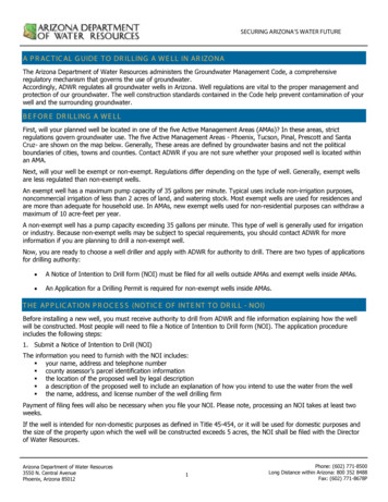
14Sperry DrillingHAL371233.7.4 TurbodrillsTurbodrill SizeWOBStringRPM HarshEnvironmentRange9.625 in.66,000 lbf/29,358 daNabove 801508.00 in.49,000 lbf/21,796 daNabove 801506.75 in.33,000 lbf/14,679 daNabove 801504.75 in.16,000 lbf/7,117 daNabove 80150String RPMSpecifiedLimit**For reaming operations with turbodrills refer to the Operations Manual D01275016HAL389313.8 TORQUE LIMITS FOR TOOL STRING OPERATIONThe torque limits for the tool string are dependent on the the componentsselected. The torque limits can be obtained from the DS-1 transmittalreport that accompanies the drill string. The values quoted are the overloadlimit for the components as calculated per the DS-1 standard methodologyfor specialty tools.3.9 DOGLEG SEVERITY LIMITS FOR TOOL OPERATIONSRotating or sliding tools through high doglegs will result in additionalwear and fatigue to the equipment. The tables below detail the HarshEnvironment Range and the specified limits for various types of tools.3.9.1 Measurement-While-Drilling/Logging-While-Drilling ToolsCollar SizeHarsh Operating ZoneSpecified Limit9.5 in.8.00 in.7.75 in.Rotating above 6 deg/100 ftNon-Rotating above 12 deg/100 ftRotating 8 deg/100 ftNon-Rotating 14 deg/100 ft6.50 in.6.75 in.7.25 in.Rotating above 8 deg/100 ftNon-Rotating above 19 deg/100 ftRotating 10 deg/100 ftNon-Rotating 21 deg/100 ft4.75 in.3.375 in.3.50 in.3.125 in.Rotating above 12 deg/100 ftNon-Rotating above 28 deg/100 ftRotating 14 deg/100 ftNon-Rotating 30 deg/100 ft
HAL32689
16Sperry DrillingHAL346093.9.2 Rotary Steerable SystemsTool SizeHarsh Operating ZoneSpecified LimitGeo-Pilot 9600Rotating above 6 deg/100 ftNon-Rotating above 12 deg/100 ftRotating 8 deg/100 ftNon-Rotating 14 deg/100 ftGeo-Pilot 7600Rotating above 8 deg/100 ftNon-Rotating above 19 deg/100 ftRotating 10 deg/100 ftNon-Rotating 21 deg/100 ftGeo-Pilot 5200Rotating above 12 deg/100 ftNon-Rotating above 23 deg/100 ftRotating 14 deg/100 ftNon-Rotating 25 deg/100 ftGeo-Pilot 9600DuroRotating above 8 deg/100 ftNon-Rotating above 12 deg/100 ftRotating 10 deg/100 ftNon-Rotating 14 deg/100 ftGeo-Pilot 7600DuroRotating above 10 deg/100 ftNon-Rotating above 19 deg/100 ftRotating 12 deg/100 ftNon-Rotating 21 deg/100 ftGeo-Pilot 5200DuroRotating above 13 deg/100 ftNon-Rotating above 23 deg/100 ftRotating 15 deg/100 ftNon-Rotating 25 deg/100 ftiCruise 9.5 in.(241 mm)Rotating above 3 deg/100 ftNon-Rotating above 12 deg/100 ftRotating above 5 deg/100 ftNon-Rotating above14 deg/100 ftiCruise 8.00 in.(203 mm)No FlexRotating above 3 deg/100 ftNon-Rotating above 13 deg/100 ftRotating above 4 deg/100 ftNon-Rotating above14 deg/100 ftiCruise 8.00 in.(203 mm) FlexRotating above 6.5 deg/100 ftNon-Rotating above 14 deg/100 ftRotating above 8.5 deg/100 ftNon-Rotating above14 deg/100 ftiCruise 6.75 in.(171 mm)No FlexRotating above 4 deg/100 ftNon-Rotating above 19 deg/100 ftRotating above 6 deg/100 ftNon-Rotating above21 deg/100 ftiCruise 6.75 in.(171mm) FlexRotating above 10 deg/100 ftNon-Rotating above 19 deg/100 ftRotating above 12 deg/100 ftNon-Rotating above21 deg/100 ft*iCruise 6.75 in.(171 mm)SuperflexRotating above 13 deg/100 ftNon-Rotating above 19 deg/100 ftRotating above 15 deg/100 ftNon-Rotating above21 deg/100 ft*iCruise 4.75 in.Rotating above 3 deg/100 ft(121 mm) No Flex Non-Rotating above 28 deg/100 ftiCruise 4.75 in.(121 mm)SuperflexRotating above 8 deg/100 ftNon-Rotating above 28 deg/100 ftRotating above 5 deg/10 ftNon-Rotating above30 deg/100 ftRotating above 10 deg/100 ftNon-Rotating above30 deg/100 ft* Additional flex components in the BHA may be required above the iCruise for high doglegapplications.
Downhole Equipment Technical Specification Information3.9.3 MotorsThe maximum dogleg severity for motors is dependent on the motor type,size, and bend setting; the dogleg severity limit of bent motors is specifiedin Section 1.10 of the SperryDrill Technical Information Handbook. Contactyour Sperry Drilling representative for the specified limits of the equipmentintended for use.3.9.4 TurbodrillsThe maximum dogleg severity for turbodrill equipment is calculated ona job-to-job basis. Contact your Sperry Drilling representative for thespecified limits of the equipment intended for use.3.10 OVERPULL3.10.1 Overpull for Logging-While-Drilling ToolsOverpull limits for LWD tools are defined by the DS-1 standard analysisperformed on every tool, and the limits for a specific string of LWD toolswill be included in the DS-1 transmittal that should accompany the tools.Connection: NC38 (3-1/2 IF)Used on 4.75 in M/LWDStress Level in Rotary ShoulderConnection During Makeup62,500 psi/431 MPaYield Strength130,000 psi/896 MPaCoefficient of Friction0.08IDForceIDForce1.00 in.850,238 lbf /378,205 daN2.25 in.569,458 lbf /253,308 daN1.25 in.811,362 lbf /360,912 daN2.50 in.487,385 lbf /216,800 daN1.50 in.763,845 lbf /339,775 daN2.75 in.396,671 lbf /176,448 daN1.75 in.707,689 lbf /314,796 daN3.00 in.297,318 lbf /132,254 daN2.00 in.642,894 lbf /285,974 daNHAL30754The following tables provide generic limits for connections on toolsfabricated from austenitic-nonmagnetic material and are calculated as theforce required to yield the pin under the defined makeup conditions. Thepin area does not depend on the OD of the collar. Calculated overpull limitsassume the case of steady pull on the collars. If shock forces are going tobe applied, such as when jarring, it is recommended to have a safety factorof at least 0.5 (multiply the overpull values in the tables by 0.5).
18HAL30675Sperry DrillingConnection: NC50 (4-1/2 IF)Used on 6.75 in M/LWDStress Level in Rotary ShoulderConnection During Makeup62,500 psi/431 MPaYield Strength100,000 psi/690 MPaCoefficient of Friction0.08IDForceIDForce1.75 in.1,304,409 lbf /580,230 daN3.00 in.931,345 lbf /414,283 daN2.00 in.1,245,504 lbf /554,028 daN3.25 in.833,170 lbf /370,613 daN2.25 in.1,178,745 lbf /524,332 daN3.50 in727,141 lbf /323,448 daN2.50 in.1,104,132 lbf /491,142 daN3.75 in.613,258 lbf /272,791 daN2.75 in.1,021,666 lbf /454,460 daNConnection: NC50 (4-1/2 IF)Used on 8.00 in M/LWDStress Level in Rotary ShoulderConnection During Makeup62,500 psi/431 MPaYield Strength100,000 psi/690 MPaCoefficient of Friction0.08IDForceIDForce2.00 in.1,698,698 lbf /755,619 daN3.25 in.1,286,364 lbf /572,203 daN2.25 in.1,631,939 lbf /725,923 daN3.50 in.1,180,335 lbf /525,039 daN2.50 in.1,557,326 lbf /692,733 daN3.75 in.1,066,452 lbf /474,382 daN2.75 in.1,474,859 lbf /656,050 daN4.00 in.944,715 lbf /420,230 daN3.00 in.1,384,538 lbf /615,873 daN
19Downhole Equipment Technical Specification InformationConnection: 7-5/8 REGUsed on 9.50-in. M/LWDStress Level in Rotary ShoulderConnection During Makeup62,500 psi/431 MPaYield Strength100,000 psi/690 MPaCoefficient of Friction0.08IDForceIDForce2.50 in.2,276,589 lbf /1,012,677 daN3.75 in.1,785,714 lbf /794,325 daN2.75 in.2,194,122 lbf /975,994 daN4.00 in.1,663,978 lbf /740,174 daN3.00 in.2,103,801 lbf /935,817 daN4.25 in.1,534,387 lbf /682,529 daN3.25 in.2,005,626 lbf /892,147 daN4.50 in.1,396,942 lbf /621,391 daN3.50 in.1,899,598 lbf /844,983 daN3.10.2 Overpull for MotorsThe maximum overpull for motors is dependent on the motor size andbend setting. For straight motors in straight hole applications, permissibleoverpull values that may be applied to the motor housings or bit, and,therefore, driveshaft and thrust bearings, can be obtained from theindividual motor specifications in Section 1.2 of the SperryDrill TechnicalInformation Handbook.The application of high overpull loads on bent housing motors, particularlyin doglegs, can result in high bending stress levels in motor housings andconnections. If possible, bent housing motors should be oriented so thebend follows the hole curvature, prior to the application of overpull loads.In high dogleg situations, directional drilling support personnel should becontacted to obtain correct overpull values.
20Sperry Drilling3.10.3 Overpull for TurbodrillsUltimate BodyOverpull(OperationDiscontinued)Max. BitOverpull WhileTurbodrill is NotOperating(AllowingContinuedOperation)Ultimate BitOverpull WhileTurbodrill isNot Operating(OperationDiscontinued)85,000 lbf /37,810 daN150,000 lbf /66,723 daN50,000 lbf /22,241 daN90,000 lbf /40,034 daN6.75 in.250,000 lbf /111,206 daN350,000 lbf /155,688 daN80,000 lbf /35,586 daN150,000 lbf /66,723 daN8.00 in.315,000 lbf /140,119 daN450,000 lbf /200,170 daN112,000 lbf /49,820 daN225,000 lbf /100,085 daN9.625 in.400,000 lbf /177,929 daN600,000 lbf /266,893 daN120,000 lbf /53,379 daN300,000 lbf /133,333 daNTurbodrillSizeMax. BodyOverpull(AllowingContinuedOperation)4.75 in.HAL39812* The application of high overpull loads on adjustable turbodrills, particularly in doglegs,can result in high bending stress levels in housings and connections. If possible, adjustableturbodrills should be oriented so the bend follows the hole curvature, prior to the applicationof overpull loads.
21Downhole Equipment Technical Specification Information3.10.4 Overpull for Rotary Steerable ToolsMax. BitOverpull WhileMotor isNot Operating(AllowingContinuedOperation)Ultimate BitOverpull WhileMotor isNot Operating(OperationDiscontinued)520029,000 lbf /12,900 daN87,000 lbf /38,700 daNGeo-Pilot GXT RSS*760075,000 lbf /33,362 daN215,000 lbf /95,637 daNGeo-Pilot GXT RSS*9600121,000 lbf /53,823 daN341,000 lbf /151,684 daNSeriesMax. dyOverpull(OperationDiscontinued)Geo-Pilot (All RSS)520060,000 lbf /26,689 daN320,000 lbf /142,343 daNGeo-Pilot (All RSS)760075,000 lbf /33,362 daN375,000 lbf /166,808 daNGeo-Pilot (All RSS)9600120,000 lbf /53,379 daN580,000 lbf /257,997 daNGeo-Pilot GXT RSS*TypeiCruise4.75 in.(121 mm)340,000 lbf /151,240 daNiCruise6.75 in.(171 mm)822,684 lbf /365,948 daNiCruise8.00 in.(203 mm)1,088,000 lbf /483,966 daNiCruise9.5 in.(241 mm)1,500,000 lbf /667,233 daN* For the Geo-Pilot GXT configuration, the maximum bit overpull for the motor definesthe operating limit, as this is connected to the rotary steerable tool.
2304Drillstring VibrationTools that are subjected to vibration and shocks will have their expectedlife reduced or will incur serious damage. Tools that contain electronics andsensor packages are particularly vulnerable.During drilling, reaming, and backreaming operations, vibration levels mustbe closely monitored and maintained below the specified limit of the toolsbeing used by applying vibration management procedures. It is acceptedthat tools may be briefly exposed to high levels of vibration before thevibration is controlled and hopefully eliminated. Damage may result whenthese high levels of vibration are sustained.The following tables define low, medium, and high levels of vibrationseverity together with the specified limits for various types of tools.The specified limit is defined by reference to the measured severity of thevibration and either its duration or number of events; the tool is deemedto have Exceeded Specified Limits when one of the criteria is exceeded.The durations or number of events are cumulative for the individual toolstring being run.HAL35341The Harsh Environment Range is entered into when equipment issubjected to high (red) vibration levels on any axis for any period of time orto a number of events that are less than that defined for the specified limit.
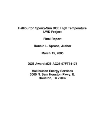
24Sperry DrillingDDS Avg X0g10DDS Peak XDDS Avg Y-10g0g10MEDg10010 20020g0MEDMWD, LWD AND ROTARY STEERABLE TOOL VIBRATION100VIBRATION SEVERITYHIGH LOW4.1 VIBRATION OPERATING LIMIT TABLESOPERATING LIMITS (DDSr , M5-DDS2, GEO-PILOT TEM)DDS Peak Z20 -100VIBRATION SEVERITYLOW200DDS Peak YDDS Avg Z0g10020 0HIGHX axis accelerometers are mounted radially. Y axis accelerometers aremounted tangentially. Z axis accelerometers are mounted axially.9 1/2” tools / Geo-Pilot 9600 / Geo-Pilot 9600 Duro: Ave Acceleration2gAve X & Ave YLOW4gMEDIUM2gAve ZLOWHIGH4gMEDIUMHIGH-2gAve X-Ave Y-1gHIGH0gLOWMEDIUM8” tools / Geo-Pilot 7600 / Geo-Pilot 7600 Duro: Ave Acceleration3gAve X & Ave YLOW5gMEDIUM2gAve ZLOW4gMEDIUMHIGH-2gAve X-Ave YHIGH-1gHIGH0gLOWMEDIUM6 3/4” tools and Smaller Tools / Geo-Pilot 5200 / Geo-Pilot 5200Duro: Ave Acceleration3gAve X & Ave Y6gLOWMEDIUM2gAve ZLOW4gMEDIUMHIGH-2gAve X-Ave YHIGHHIGH-1g0gLOWMEDIUMAll Tool Sizes: Peak Accelerations30gPeak X & YLOW15gPeak Z90gLOWMEDIUMHIGH40gMEDIUMHIGH
25Downhole Equipment Technical Specification InformationAll Tool Sizes: M5-DDS2 Shock (Short Average) Acceleration15gPeak X & YLOWMEDIUM10gPeak ZLOW30gHigh-SpeedComms PortHIGH20gMEDIUMHIGHAverage X, Y in the high zone for 18 minutes or greater and tools haveexceeded specified limits. For certain Geo-Pilot Duro BHA’s the limit is 30minutes.Average Z in the high zone for 8 minutes or greater and tools haveexceeded specified limits. For certain Geo-Pilot Duro BHA’s the limit is 15minutes.Mud Resistivityand TemperatureAverage X-Average Y in the high zone for 18 minutes or greater and toolshave exceeded specified limits.Peak X or Y in the high zone for 150 events or greater and tools haveexceeded specified limits. For certain Geo-Pilot Duro BHA’s the limit is 250events.Peak Z in the high zone for 100 events or greater and tools have exceededspecified limits. For certain Geo-Pilot Duro BHA’s the limit is 150 events.For details of Geo-Pilot Duro BHA’s contact your Sperry representativeEWR -M5DDSr STICK-SLIP INDICATOR (SSI)All Tools Torsional Efficiency %100%0%SSILOW150%MEDIUM200%HIGHSSI between 100 percent and 150 percent for greater than 12 hours and tool isoutside limits. SSI greater than150 percent for greater than 30 minutes andtool is outside limits. For certain Geo-Pilot Duro BHA’s the high threshold is200% and the duration is 60 minutes.Note: Contact your Sperry Drilling representative for details of the Geo-Pil
10Sperry Drilling 3.3 LOW GRAVITY SOLIDS A high concentration of low gravity solids (LGS) is detrimental to the performance of all downhole tools and can lead to tool erosion. A concentration of 6% LGS is the specified limit for all Sperry downhole tools. 3.4 LOST CIRCULATION MATERIALS